Announcement

Collapse
No announcement yet.

Tesla's Magnifying Transmitter "Replications"

Collapse
X
 
  • Filter
  • Time
  • Show
Clear All
new posts

  • Hi dR,

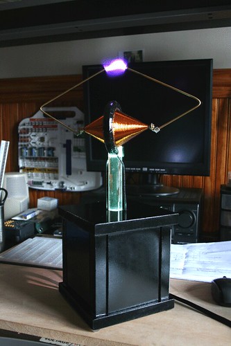
    420mA for that? Doesn't look bad at all Can you drive the input with more power? I mean, that's a 25w bulb with 5w input, so what happens if you increase the input.

    The bulb is also brighter between my coils than the receiver output, but we seem to have the opposite effect happening. With a bulb between the coils my receiver output is reduced or non-existent, but with a fluoro it isn't really affected. A 1k resistor doesn't really affect it either, the bulb is about 360 ohms if I remember correctly.
    I can use more power yeah but only by either changing my primary circuit like
    Dragon said, less turns more capacitance or by using a higher input voltage.
    If I use more everything gets brighter.

    It's funny because if there is more load on the receiver the potential drops
    and so does input power but the light in the connecting wire gets dimmer.

    The thing I also noticed is that I can take the wire from the fluro to the
    receiver off and the fluro is lit then only by one wire from the transmitter
    much the same. So I'll have to think about that one. Ahah ! Must be the frequency,
    mine will go through the bulb without filter "low pass" and not the fluro "high
    pass" because I have 480 Khz and your's is opposite because you have 8 Mhz.

    Certain filters can allow high frequency to pass but block low frequency that's
    a "high pass" filter I think and it's opposite for the low pass filter.

    480 Khz is closer to 35 Khz than is 8 Mhz but not close enough for the
    cookie so we will both have to be satisfied with a wire instead for now.

    I can go to 24 volts input but more and I will need to change my caps out for
    higher voltage ones because the transmitter tank caps gets peaks of 35 or
    more volts in it as the scope shots show with a 12 volt input. Also then all my
    analogue voltage meters won't be enough for the receiver and things might
    burn up. I think I smoked the resistors on the LED board powering it with 120
    volts in a 40 volt cap charged from the receiver. I'm lucky I haven't
    blown a cap yet. Iv'e taken 275 volt caps to over 800 volts.


    I also forgot to mention earlier, I had a bit of an epiphany after playing with an AV plug and LEDs the night I drained the battery. This might be obvious to others already or irrelevant but it suddenly made sense to me and at least helps me in terms of being able to think about it. Walking around the room with the AV plug, I noticed that it was working up to about 8 feet away from the coils. But then I realised I could make it brighter in my left hand by extending my right hand into the field of the coil. So I was clearly becoming a conductor and my body could transfer the energy to light the LEDs. This got me thinking of how to light LEDs remotely with a conductor near the coil, but then that would require wires from the conductor to the LEDs, which would defy the point. And then I realised, THE EARTH. The earth is a "physical body" like mine, it extends to all "remote locations" and in all directions except up, it can touch the terminal of the coil directly where I fear to do so, and it can also be in direct contact with the receiving load, in this case the AV plug.

    So I don't know what that means to anyone else, but now I think I'm starting to understand, or at least I have a concept to be able to think about the whole thing.
    Yes some of these revelations are astonishing. Good stuff. It's also funny how
    simple it really is, but how difficult it is to understand and explain.

    Hmm I think I need to have a think about all the info we have both gathered
    in these observations and ponder.

    Thank you for sharing.

    Cheers

    P.S. I need to make a list of effects and observations I want to show and make a good video to show them all in one video.
    Last edited by Farmhand; 10-07-2011, 01:49 AM.

    Comment


    • Alright I forgot, this sounds very interesting, I might try transmit through some dirt experiments inside. Series connected plant pots or something.

      Something I want to try is put a fluoro in a bottle of water. First to see what will happen, and also the water/bottle should scatter the light. Also some AV plugs and LEDs in water.
      Once again I'm battling chores building up and trying to study too so experiment time is short just now.

      Cheers

      Comment


      • Hey dR, I think if you use a Transformer from the grid power to run the
        ignition coil it will be max current for the load (transformer) not sure that is a
        good idea.

        I would look into using triacs or something to regulate the current.

        I notice my variable speed vacuum cleaner has some way to regulate power
        quite well with a few simple componants on a very small board.

        Maybe the current in the low voltage circuit can be regulated some easier
        way and be effective. It could be dangerous because the only isolation
        between the grid and the ignition coil is the internal transformer insulation. I
        would recommend reading up on it a bit. A very simple circuit could make it a
        safe and viable option.

        Please be careful .

        EDIT: Sorry for the edits I hope you don't miss them, it keeps the post count down.

        The other thing is that for charging the HV cap we really want to use as high
        a frequency as the Ignition coil or fly-back will handle well. I think the fly back
        will want high frequency and the ignition coil likes a capacitor and medium
        frequency.

        All in all I think the best way is to run your circuit from a big capacitor filled by rectified output from a step down transformer from the grid. Pulse the ignition coil or fly-back with you're circuit.

        I have a home wound 6.5 inch iron powder toroid wound like a Tesla converter
        for AC it has 136 turns as secondary and two sets of opposite series
        connected coils at 90* to each other each set is 32 turns and pulsed 180*
        out of phase one of the primary coil sets is switchable on/off and reverseable.
        So I can have AC or DC very Square wave and half power at the flick of a
        switch, it outputs about 65- 70 volts. But I can also adjust the PW and
        frequency to change power through different loads. I had to fit a primary
        charging circuit to get good power through at higher frequencies other wise
        as frequency increases power in and out diminishes. At 60 Hz lots of Amps
        can go through it over 20 amps I've seen through it by accidentally switching
        from 100 Khz or so to less than 60 Hz while running with a 40% duty cycle.
        Luckily the secondary was charging a battery.

        Using this method works for me to drive the ignition coil but only because the
        converter circuit can charge a battery while it drives the coil so there is no
        heat waste, it seems depending on the type of load depends on the action
        the recovery charge battery gets.

        I've got wiring diagrams and stuff but it's all experimental, however it will be
        useful for converting different types of currents which is it's main purpose.

        My method still rely's on a battery so not very useful to you. We still must do
        what is useful to us.
        Last edited by Farmhand; 10-07-2011, 03:56 AM.

        Comment


        • This got me thinking of how to light LEDs remotely with a conductor near the coil, but then that would require wires from the conductor to the LEDs, which would defy the point.
          Actually if you use one wire and connect the AV plug to the connecting wire
          between the coils it should light up, might even blow without a resistor. And it is
          possible you might tune the coils closer to each other a bit by varying the things
          connect to or around them. Another thing with the LED is if you use a big piece
          of metal and connect the AV plug to that and try letting go of the LED.

          I did find just connecting a large metal mug to the connecting wire it improved
          the output a bit. I think that increases the capacitance of the "ground circuit"
          to more than the terminals.

          Cheers

          Comment


          • I remembered I had a multi-tap step down transformer in a box I used to use, so
            I got it out to show you, now I'm thinking I might be able to use the 30 volt tap
            to charge a big cap to run my setup from.

            I set mine up by soldering the 220 winding of the transformer to the existing
            circuit board in a computer power supply box , then the low voltage winding
            that I tap comes out and plugs into a big bridge rectifier and I charge a big
            supply cap from that i'll use a good 4000 uF electrolytic capacitor and run the
            circuit from that. I'm not sure if it's legal to use it from the grid so I'll state
            that I only use mine from an inverter powered by a battery

            Here's some picture's.

            It needs a clean, the red wire's are 220.


            Uploaded with ImageShack.us

            The transformer is bolted to the case and the case is grounded by the input
            lead ground for safety. Safety first ! It's a good idea to make
            certain the 220 can't touch the upper case mine looks close actually.


            Uploaded with ImageShack.us

            Then of course it's all covered up and only low voltage wires are touchable.
            Always unplug before opening of course. Sorry about the safety rant but we
            gotta stay safe.


            Uploaded with ImageShack.us

            Good idea dR.

            Comment


            • Originally posted by Farmhand View Post
              Finally I am able to light a fluorescent bulb from the secondary of a MOT by
              pulsing the primary with some caps charged by the receiver coil.
              Nice I'm finally starting to be able to light a fluoro directly from the receiver secondary since last night. I'll get back to this in a minute.

              I'm opposite, I don't like using the grid, but I have a lot of big batteries and
              some solar panels and HF desulfators, so I'm setup for it.
              I don't really want to, but I don't have big enough batteries, the one I've been using so far was headed for the skip because it was useless. So I want to be able to experiment without having to stop because the battery is flat and all that.

              That will only be true if the transmitter is connected to the ground and
              transmission is through the ground. Because the transmitter in that case is
              tuned to transmit through the ground and connecting a receiver to the huge
              earth will have little effect on the transmitter. However if not using the
              ground then what as the transmission medium ? If it's only a wire then
              connecting the receiver coil to that will have a large effect. Then there is the
              "near object" thing and the "body effect" when near the coil also.
              Good point, I think you might have mentioned this before actually. I haven't noticed such a big effect with near objects and what not with the spiral coil though. When I was playing with the simple SEC and helical coil the effect was obvious, but I haven't noticed enough (anything at all in fact) to be concerned with it in this setup.

              What is connected to the outer end of the HV winding of the transmitter ?
              The secondary? That's where I've been putting the bulb.

              Yeah supposed to be but obviously not
              This is what I find fascinating. And this reminds me, I was watching a program on BBC about the story of electricity 2 days ago. I'll post a link if it's on youtube, but for example he says along the lines of "we now completely understand electricity and we can make it do our will" or whatever. The usual human arrogance of believing they have mastered a part of nature. But I've easily produced an effect in my bedroom with a tiny budget that completely disproves this "fact" they are brainwashing the world with I mean, to me it's no longer information in videos on youtube etc or the possibility that people are exaggerating things or plain lying, it's easily recreated and there it is, it proves that they DON'T know everything about electricity. So what can I say, I have to have a different view of the world when they are spreading such information and I know different.

              Anyway, I can't find the program on youtube yet, but it's a series anyway and there's only been 1 episode so far. This is a preview

              The Story of Electricity preview - BBC Four - YouTube

              And I also came across this while searching for that. Dunno if he's acting or not but it looks funny. And from a serious perspective could be relevant here. Translation of the video: She basically says they didn't know if he was acting so they filmed him again in slow motion, and he doesn't react with a jump, but his back bends back which is a natural reaction to a shock in the shoulders.

              Electric Shock from Standing Stone - BBC Cymru - YouTube

              I didn't know you had turns on top of turns, I would have changed groves one
              groove back and keep the wires separated, is there no arcing there ?
              It makes up the "complex network of mutual inductance and capacitance" Eric Dollard talks about. Which I don't really understand, but the way I see it, I have a 2 turn primary, so the 2 turns are mirrored throughout the whole coil. If I had a 4 turn primary I'd put 4 turns on top of each other in the secondary. There's no arcing, presumably because the potential difference between each layered turn isn't big enough.

              Must be the frequency,
              mine will go through the bulb without filter "low pass" and not the fluro "high
              pass" because I have 480 Khz and your's is opposite because you have 8 Mhz.
              Could be But I just tried something with I'll get to because you also mentioned something else...

              Alright I forgot, this sounds very interesting, I might try transmit through some dirt experiments inside. Series connected plant pots or something.
              I also thought of this before, but figured that since a bucket of mud wouldn't be connected to the earth then there wouldn't be much point. But since my "revelation" the other night the thought came back to me, and then you mentioned it.

              So earlier I tried it. And it worked The filament is lighting at the receiver through 2 copper pipes pushed into the opposite ends of a bucket of soil That's literally as far as I got before coming to reply here.

              Once again I'm battling chores building up and trying to study too so experiment time is short just now.
              At least on the plus side the studying will come in handy when you have the time to experiment

              Hey dR, I think if you use a Transformer from the grid power to run the
              ignition coil it will be max current for the load (transformer) not sure that is a
              good idea.
              Nope. It's not, lol. I made a simple test. Transformer > ignition coil, and then transformer > rectifier > 555 > ignition coil. No question about it. So I now have 4A worth of transformers going through a rectifier with 5000uF cap powering the 555. The 15V AC becomes 21V DC, so I have better performance than before, and the input current also seems to be either the same or less at the same settings, with increased output. So that's a step forward I would say. Now the problem is the rectifier and transistor are getting hot, so always more obstacles to overcome

              Your concern is duly noted

              I don't quite understand what that transformer of yours is. Are you able to change the AC frequency?

              Actually if you use one wire and connect the AV plug to the connecting wire
              between the coils it should light up, might even blow without a resistor.
              Yes I wouldn't like to try that really I find the output to be very deceptive. It looks pretty harmless, relatively small sparks etc, but when it wants to it can do surprising things. I nearly had a small fire on my hands a couple of days ago when my modified Edison holder met with a vulnerability in the wire insulation, damaged (squashed) by the crocodile clip of the helping hands during soldering due to the heat. It managed to breach the insulation and went up in a bright spark and puff of smoke before I quickly turned off the power. I can't see an LED lasting long

              I'll try playing with an AV plug now. Also got 200 1N4148 delivered today so I'll be building plenty. First test will be to stick a wire into the soil with the copper pipes from the coils.

              I'm not sure if it's legal to use it from the grid so I'll state
              that I only use mine from an inverter powered by a battery
              Good idea about using the box. I spent 2 or 3 days designing and building boxes to put these transformers in. I definitely agree about the safety. But, for some reason I find it ok to have spark gaps and exposed metal with thousands of volts going through it on the desk, but I have to build a box for 240V

              Why would it be illegal to use a transformer? That looks good anyway. Do mean running the setup off the mains? Thanks, I like the idea of using an existing power supply box. Pity you didn't mention that sooner lol.
              http://www.teslascientific.com/

              "Knowledge is cosmic. It does not evolve or unfold in man. Man unfolds to an awareness of it. He gradually discovers it." - Walter Russell

              "Once men died for Truth, but now Truth dies at the hands of men." - Manly P. Hall

              Comment


              • Good job on the experimenting and improvements. If it works do it. that's
                what I do. hehehe

                I haven't had time to do anything yet, I've been distracted.

                Which transformer do you mean ? My home wound one ? I can make a drawing
                to explain it better, it is difficult to explain so I can understand.
                I don't quite understand what that transformer of yours is. Are you able to change the AC frequency?
                ..
                The secondary? That's where I've been putting the bulb.
                Yes I see. My bad.

                OK I think I understand this, I'm not familiar with the methods of winding the
                spirals yet. If there is no arcing it must be OK.
                It makes up the "complex network of mutual inductance and capacitance" Eric Dollard talks about. Which I don't really understand, but the way I see it, I have a 2 turn primary, so the 2 turns are mirrored throughout the whole coil. If I had a 4 turn primary I'd put 4 turns on top of each other in the secondary. There's no arcing, presumably because the potential difference between each layered turn isn't big enough.
                ...

                Nope. It's not, lol. I made a simple test. Transformer > ignition coil, and then transformer > rectifier > 555 > ignition coil. No question about it. So I now have 4A worth of transformers going through a rectifier with 5000uF cap powering the 555. The 15V AC becomes 21V DC, so I have better performance than before, and the input current also seems to be either the same or less at the same settings, with increased output. So that's a step forward I would say. Now the problem is the rectifier and transistor are getting hot, so always more obstacles to overcome
                That's very good, the heating might be too much pulse width. Or maybe just
                the increased voltage, do you have heat sinks.

                If you can reduce the PW and increase the frequency you can have the same
                effect with less current up to a point, depending on a few things.
                Can you adjust the PW of the 555 circuit ? There is a simple mod that can be
                made to do that with a 555, I use the mod to narrow the PW on my cap
                discharger, it's a different chip but same oscillator timing method kinda, so it works.

                What frequency are you using the 555 at ?

                Then there is also another method I've used as well to improve transformer
                action which is "gating" or grouping where the normal PW is broken up into a
                group of pulses of a certain lesser width. So instead of only one event per
                pulse there are a few or many. This increases the effective frequency x pulses
                per group but requires a second chip. And you can already get high enough
                frequency for you're ignition coils anyway.

                ..

                That is true the zap from there can hurt even from my setup, it's a hot arc
                but once contact is made there is no heat. At least not for me.

                Yes I wouldn't like to try that really I find the output to be very deceptive. It looks pretty harmless, relatively small sparks etc, but when it wants to it can do surprising things. I nearly had a small fire on my hands a couple of days ago when my modified Edison holder met with a vulnerability in the wire insulation, damaged (squashed) by the crocodile clip of the helping hands during soldering due to the heat. It managed to breach the insulation and went up in a bright spark and puff of smoke before I quickly turned off the power. I can't see an LED lasting long
                Sorry I didn't mention about the transformer and rectifier before. The
                grounding makes it kinda safe. But it also shows why we shouldn't really use
                the house ground for grounding our HF coils. Because the house ground is
                connected to a lot of the household appliances.

                Anyway can't wait to hear more, i'll get around to setting up my Transformer
                in a box to run my transmitter from soon and make a report.

                Cheers

                P.S. I hope to get around to making some custom Printed Circuit Boards soon,
                for the variable frequency PWM circuits I want, which will be two phase but
                both phases don't need to be used. I can make extra's when I do.

                I'm thinking of a circuit that has variable frequency and pulse width on two
                phases capable of 60 Hz to 200 Khz with PW adjustable from 48 % duty to nil.
                And with the possibility of running whatever switched voltage up to the
                mosfet rating, so two supply points one for the PWM circuitry and one for the
                load/load's to be switched. A good board design would allow for only the
                needed parts to be used for the intended purpose.

                ..
                Last edited by Farmhand; 10-09-2011, 03:31 AM.

                Comment


                • Originally posted by Farmhand View Post
                  Which transformer do you mean ? My home wound one ?
                  Yes.

                  That's very good, the heating might be too much pulse width. Or maybe just
                  the increased voltage, do you have heat sinks.
                  Maybe. I read that ideally R2 should be approx 10 times the value of R1 in the 555 circuit, and I've only been going 11k and below with R2, and 1k and above with R1. So I plan to get a couple of 100k pots, and also I need to build a box for the 555 because there's HV all over it and adjusting things is a case of finding external forces to work against and turn the pots. Also the metal screw driver making contact with my carbon preset in adjusting it clearly changes the frequency, then I turn it to a certain value, remove the screw driver and the frequency changes again. So that's not ideal. I'm not sure what frequency I'm using at the moment, haven't been using the scope on it lately.

                  I've got heatsyncs on both transistors although only one gets hot, but nothing on the rectifier. Didn't expect it to get that hot. Nothing has fried yet though. All my components are at least above the current rating of the transformers. The 555 is pushing it though, I think that's 15-18v max and I'm using 21v.

                  Something I'm thinking of though is putting a rectifier between the 15-20v AC of the transformer and use that to supply the 555, then use my original circuit with the opto and 21v supply for the flyback and transistors.

                  Anyway I think the PW is adjustable. From the scope it looks like that's what R2 is mostly doing.

                  Sorry I didn't mention about the transformer and rectifier before.
                  No worries, the thought had crossed my mind and in fact that's exactly what I was doing when you were writing it. I was coming here to read between things but I was up until 9am fiddling so replying had to wait I'm afraid It looks like my sawing skills are improving with all this box making anyway

                  But it also shows why we shouldn't really use
                  the house ground for grounding our HF coils. Because the house ground is
                  connected to a lot of the household appliances.
                  That's true, but seeing as I can't have a cable going out the window that's what I've been using and nothing has exploded and no one has complained about any interference yet so I've kept on using it. But either way, I've noticed an interesting difference by earthing it that way and just using a completely open loop. The bulb gets brighter which is obvious by now, but also the input goes down

                  Anyway can't wait to hear more, i'll get around to setting up my Transformer
                  in a box to run my transmitter from soon and make a report.
                  That should be good That circuit sounds like it would be handy too. Good luck I have to post the rest in a separate reply due to limits...
                  http://www.teslascientific.com/

                  "Knowledge is cosmic. It does not evolve or unfold in man. Man unfolds to an awareness of it. He gradually discovers it." - Walter Russell

                  "Once men died for Truth, but now Truth dies at the hands of men." - Manly P. Hall

                  Comment


                  • Here are some pics of the bucket of soil setup and the power supply. I can fit another 2 transformers in here


                    30cm lengths of copper pipe in soil from the garden, not even half way in by the looks of it


                    This is using the house/mains socket earth


                    My bucket of soil


                    The 12v 21 LED on the receiver with 2 bulbs in parallel at the transmitter. It won't work with only 1 bulb


                    Without the bulbs


                    The bulb at the receiver


                    There's a lot more things. I also made a video but I'll have to convert it and edit it and upload it, so I'll do that tomorrow. One strange thing to mention is that the fluoro won't light at the copper pipe in soil that goes to the receiver, but it starts lighting where the wire from the soil enters the coil. At the terminal D' I get small sparks. And the sparks have increased to nearly 1cm long at terminal D. All through soil. Very interesting

                    [edit] I forgot to mention, input is between 1.35-1.8 amps.
                    Last edited by dR-Green; 10-09-2011, 08:00 AM.
                    http://www.teslascientific.com/

                    "Knowledge is cosmic. It does not evolve or unfold in man. Man unfolds to an awareness of it. He gradually discovers it." - Walter Russell

                    "Once men died for Truth, but now Truth dies at the hands of men." - Manly P. Hall

                    Comment


                    • Originally posted by Farmhand View Post
                      I'm thinking an adjustable Spark gap with a U shaped electromagnet
                      What about a bi-filar electromagnet coil, pulsed to save energy, and also use the 2nd winding to capture the spike. In other words, a Bedini style electromagnet

                      I also had an idea of how to make spheres out of toilet floats or any other non-metallic suitably shaped material. (Which by the way I came across 6 inch diameter floats without the bump in the middle, which may come handy...) Anyway, aluminium or copper spray. Assuming you can get hold of the metallic stuff and not just paint, then you could spray this onto whatever and make a nice terminal. That's the idea anyway.

                      And on the bigger float, I noticed earlier using the bucket of soil between the coils, the LED on the receiver got brighter when I put the 8W fluoro onto the terminal D of the transmitter. So this is the opposite effect of what was happening before. Now I have increased output by getting more light from terminal D, compared to before where a fluoro at terminal D seemed to suck energy from the system. So perhaps more capacitance, or a bigger terminal might be better. I'll have to try to find some aluminium or copper spray and test the 6 inch ones.
                      http://www.teslascientific.com/

                      "Knowledge is cosmic. It does not evolve or unfold in man. Man unfolds to an awareness of it. He gradually discovers it." - Walter Russell

                      "Once men died for Truth, but now Truth dies at the hands of men." - Manly P. Hall

                      Comment


                      • Originally posted by dR-Green View Post
                        What about a bi-filar electromagnet coil, pulsed to save energy, and also use the 2nd winding to capture the spike. In other words, a Bedini style electromagnet

                        I also had an idea of how to make spheres out of toilet floats or any other non-metallic suitably shaped material. (Which by the way I came across 6 inch diameter floats without the bump in the middle, which may come handy...) Anyway, aluminium or copper spray. Assuming you can get hold of the metallic stuff and not just paint, then you could spray this onto whatever and make a nice terminal. That's the idea anyway.

                        And on the bigger float, I noticed earlier using the bucket of soil between the coils, the LED on the receiver got brighter when I put the 8W fluoro onto the terminal D of the transmitter. So this is the opposite effect of what was happening before. Now I have increased output by getting more light from terminal D, compared to before where a fluoro at terminal D seemed to suck energy from the system. So perhaps more capacitance, or a bigger terminal might be better. I'll have to try to find some aluminium or copper spray and test the 6 inch ones.
                        Very good idea, metallic spray of some kind might just work even paint or dare
                        I say it "electroplated"

                        Good observations too, you are correct by increasing the effective
                        capacitance with the proximity of you're body and fluro the resonant
                        frequency of the secondary is lowered this means that the primary is a bit
                        lower resonant frequency than the secondary and good for demonstration of
                        the fluro lighting and stuff.

                        If you want to better match them there are two ways to go and two ways to do each,
                        you could decrease the primary capacitance and raise its frequency, or
                        increase the secondary capacitance and lower its frequency, either way will
                        match them up, then the trick is to do the same with the receiver, then you
                        can blow bulbs.

                        The other way to adjust the resonant frequency is to add small variable
                        inductors but I don't think you need to worry about that.

                        I'll link this stuff here about the converter.

                        This is a circuit drawing but it doesn't show that the core is toroidal or the
                        secondary. EDIT: The coils are wound CW-CCW they are fired CW-CCW around the toroidal core.
                        But thats for AC for DC use they are fired all CW.


                        Uploaded with ImageShack.us

                        Here is some video's if you haven't seen them yet.

                        Converter.
                        Converter.wmv - YouTube

                        This one shows the what the switch does.
                        Converter Coil Switch.wmv - YouTube

                        In this one I discovered that if a commercial 12v to 220 v inverter is run from
                        the battery next to the one the circuit is grounded to I can do wireless
                        energy transmission with the noise from one battery to the other, so I worked out
                        later. I think I had the converter tuned resonant to 60 Hz. hehehe
                        During the video I got a bit miffed because it shouldn't have been doing that,
                        and I couldn't work out why it was, the next night I worked it out.

                        Rotating Magnetic Field.wmv - YouTube

                        I didn't miss you're last post but I plan to experiment like that tonight so I'll
                        comment then. Short on time too.

                        Cheers
                        Last edited by Farmhand; 10-16-2011, 02:27 AM.

                        Comment


                        • Originally posted by dR-Green View Post
                          What about a bi-filar electromagnet coil, pulsed to save energy, and also use the 2nd winding to capture the spike. In other words, a Bedini style electromagnet
                          I found a better drawing of the magnetically quenched spark gap Page 306 of the IRWNT book. looks like just a coil with a lot of wire and the poles are extended so the coil is far enough below the gap and the added pole piece projections are adjustable and shaped.


                          Uploaded with ImageShack.us

                          I used some pots of dirt between my coils last night just with the normal
                          12 volts input and results were fairly good, with three pots in series the
                          receiver output was reduced a little bit, the resistance with three pots is over
                          7 Kohms, if i use only one pot which is about 2.4 Kohms the receiver output is
                          only affected a bit I can still run 1 fluro and the LEDs directly from the
                          receiver output coil and one fluro from one end standing in the holder.


                          Uploaded with ImageShack.us

                          Received through one plant pot of dirt. Mine has some granite in there and
                          lots of rocks.


                          Uploaded with ImageShack.us

                          Still didn't get the transformer setup, I hope tonight.

                          Oh yeah I was thinking if you want to run a small motor you might need to
                          rectify the receiver output into an electrolytic capacitor then run the DC motor
                          from that, that's what I do it will run from the DC of the bridge with no DC cap but not as well.

                          Cheers
                          Last edited by Farmhand; 10-10-2011, 11:44 PM.

                          Comment


                          • Originally posted by Farmhand View Post
                            I found a better drawing of the magnetically quenched spark gap Page 306 of the IRWNT book. looks like just a coil with a lot of wire and the poles are extended so the coil is far enough below the gap and the added pole piece projections are adjustable and shaped.


                            Uploaded with ImageShack.us


                            Cheers
                            Farmhand, notice the endings of each pole..."2 cones" and a " a disc" if viewed sideways

                            Last edited by MonsieurM; 10-11-2011, 12:04 AM.
                            Signs and symbols rule the world, not words nor laws.” -Confucius.

                            Comment


                            • Hi Monsieur, Now that you mention it, yeah I do see that. It is remarkable how
                              many things that work actually resemble the opposing vorticies (sp) and
                              equatorial ring. A magnetic north and south on a sphere and rotating equatorial
                              ring is the planet.

                              That is kinda cool. I wonder if Tesla himself noticed these things and kept it in
                              mind. Thanks for pointing that one out.

                              I wonder what would happen if the magnetic poles of the Earth were rotated
                              around and around in a circle like the rotating magnetic field in a Tesla motor
                              Field, while the earth was still rotating on it's axis. Just the magnetic field was
                              made to rotate around the surface from North to East then South then West
                              and around, but in smooth progression.

                              I don't mean what would happen to us but the dynamic result.

                              Wow, So to test it we need a metallic sphere rotating on it's axis, then induce
                              a rotating magnetic field in the sphere at right angles to the rotation of the
                              sphere. If the field which induces the rotating field on the sphere is rotating
                              with the sphere then it would cause a rotating field that is itself rotating.

                              Isn't that a magnetic gyroscope.

                              It could be done with a rotating ring instead of a rotating sphere even. Much
                              easier. A rotating magnetic field in a rotating ring, maybe not the same but close.

                              Hows that sound Monsieur ! Fun ?

                              Comment


                              • Originally posted by Farmhand View Post
                                Hi Monsieur, Now that you mention it, yeah I do see that. It is remarkable how
                                many things that work actually resemble the opposing vorticies (sp) and
                                equatorial ring.
                                A magnetic north and south on a sphere and rotating equatorial
                                ring is the planet.

                                That is kinda cool. I wonder if Tesla himself noticed these things and kept it in
                                mind.
                                Thanks for pointing that one out.


                                Hows that sound Monsieur ! Fun ?


                                He did, he just did not write it in the right order he would have made it easier if he said 6 3 9

                                "If you only knew the magnificence of the 3, 6 and 9, then you would have a key to the universe." Tesla
                                Signs and symbols rule the world, not words nor laws.” -Confucius.

                                Comment

                                Working...
                                X