Announcement

Collapse
No announcement yet.

Tesla's Magnifying Transmitter "Replications"

Collapse
X
 
  • Filter
  • Time
  • Show
Clear All
new posts

  • Farm,

    You may find this interesting.

    Are you sure that your coils are operating at 1/4 wave?

    it seems to me that one of those articles you had from tesla said the transmitter as a system needed to be adjusted for 1/4 wave and of course if you want to get any kind of real power out of it, it wil also need to have a nice standing wave for both your transmitter and rec at the operating freq.

    Beyond matching them to be identical resonators mechanically then matching the impedance for a good transverse standing wave, then retune the freq like meyl to match the 1.2 - 1.57 speed I would think that is all the is necessary to get max output aside from raising the voltage and getting them up in the rarified air as tesla put it.


    I think you will find this interesting.


    Transverse & Longitudinal Electric Waves - Eric Dollard And Thomas Joseph Brown on Vimeo

    Tesla's Longitudinal Electricity - Eric Dollard, Peter Lindemann & Tom Brown on Vimeo

    Standing Waves Generated by String Vibration - YouTube

    Loop antenna resonance measurement with the MFJ-259B - YouTube

    Standing Wave Ratio explained - YouTube

    ECE3300 Lecture 12b-8 Smith Chart VSWR, lmin,lmax - YouTube

    ECE3300 Lecture 13b-1 Impedance Matching Intro - YouTube


    Homebrew antenna tuners - YouTube

    LL-Tuner by PA0LL.mpg - YouTube

    ECE3300 Lecture 6 4 Standing wave ratio - YouTube


    ECE3300 Lecture 30-1 Plane Wave Reflection and Transmission, Oblique Incidence - YouTube
    ECE3300 Lecture 30-3 Plane Wave Transmission and Reflection, Oblique Incidence - YouTube
    ECE 3300 Lecture 30-2 Plane Wave Reflection and Transmission, Oblique Incidence - YouTube

    Last edited by Kokomoj0; 11-13-2011, 07:40 AM.

    Comment


    • from the vid, it looks like eric wound a distributed capacitance coil?


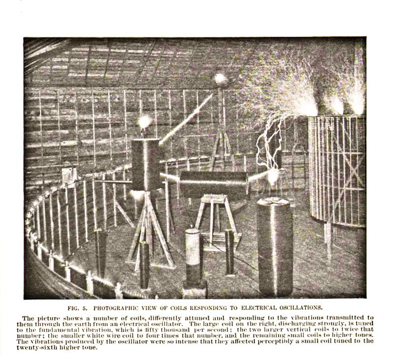
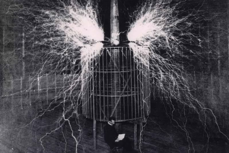
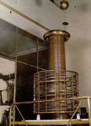
      here are a few of teslas design


      it looks like its nearly log spacing toward the top?


      Here is more:

      I have gotten emails over the years and do not know where most of this stuff comes from, if there is a problem with posting it email me and I will be happy to remove whatever.....


      another coil that looks like they used distributed capacitance which could be for insulation and or could also be required for proper design?
      Last edited by Kokomoj0; 11-13-2011, 05:27 PM.

      Comment


      • Originally posted by dR-Green View Post
        Yes, but I don't think that's an indication as to what gauge of wires to use, it just narrows the range depending on where you're starting from. There are a lot of different combinations you could use to get particular lengths and matched weights.

        Anyway I don't think it's necessary in order to get results, but I do think that it forms a deeper level of tuning.

        As for my spiral coils, being a complete experiment and having no idea how much wire I'd need or what gauge, it was the only indication - how much copper was in the primary. Make the secondary match it, and see how it turns out. I don't even know if they are tuned in any way whatsoever besides the weight, they just do what they do
        The reason I mentioned this, is if you think of a copper wire say 9 meters long, this wire has a certain set number of atoms with its set weight....now take that wire and shrink it to 1 meter without changing that set amount of atoms....the only way you can do that is if you make the wire with a larger diameter.....I hope this clarifies my thought....
        Signs and symbols rule the world, not words nor laws.” -Confucius.

        Comment


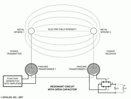
        • Can some one fill me in on Eric Dollards best result for energy transmission
          through the natural medium ? Or his best transmission of energy over a
          distance ? Because the best I seen was when he used some type of extra
          equipment (amplifier or something) to enhance the signal he got from his
          transmitter to his receiver, and it seemed all he got was not much more than
          some noise.

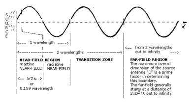
          I agree about the distance thing and most of these types of demonstrations
          very close to the coils. but I don't see how it can be called a near field effect
          when using two separated transformers and power is taken from the output
          coil (load powered with wire's) when the receiver is far enough away say 4 meters
          so that a LED with an AV plug wont work halfway between them, and if when
          the connecting wire joining the two negative or bottoms of the secondaries is
          disconnected all power stops.

          I can transmit from inside one completely steel lined shed to another one
          20 meters away and it still works. It works because the connecting wire
          (ground wire) is where the energy is sent. It's plain to see by the way a light
          will glow when placed in series in the ground wire between the coils a
          fluro works well, so obviously a lot of energy is going back and forth through
          the wire, that's good enough for me.

          The losses from the wire to the ground make any long distance transmission
          with a wire laying on the ground hopeless and transmitting through the ground
          won't happen without a setup which is resonant below 25 Khz. SO I can't see
          the 1 1/2 wavelength thing happening. Unless with very high frequency so the
          coils would be close anyway.

          My coils work at 430 Khz so to place the coils 1 1/2 wavelengths apart I
          would need to put them 1 Klm apart. Considering I am working alone I don't
          think that will happen. Showing anything less is pointless.

          Even for 7 Mhz the coils would need to be 65 meters or so apart, did Meyl show that ?

          Seems if he didn't his demonstration means nothing.

          In my opinion there are near field effects but there are also other effects that
          happen when the coils are close that also happen when the coils are far apart.

          For instance if I take a neon and hold it by one leg near the transmitter
          terminal it glows, but 30 cm from the terminal it won't glow. It won't glow
          anywhere in the distance between the coils until it is held close to the
          receiver terminal when it glows again, then if I disconnect the ground wire it
          stops immediately just like the wired load powered from the receiver.

          It's a catch 22 situation here. I'm not going to buy into it and get distracted
          by it.

          Cheers

          Comment


          • This is really old, like 80's maybe? So I think this is just proof of concept using pancake coils rather than the full tower setup.

            its toward the end in this first one. But this is certainly not intended as a distraction. I posted this stuff and the previous dor informational purposes, because dollard went over how to test to see if the magnetic and dielectic are in phase along the Tline etc, and swr can tell you where your voltage node(s) are as we were talking about in lamares thread.


            Eric Dollard Peter Lindemann Tesla's Longitudinal Electricity - YouTube


            Eric Dollard Tesla Longitudinal wave Energy SBARC Ham Radio with Chris Carson - YouTube
            Last edited by Kokomoj0; 11-14-2011, 05:32 AM.

            Comment


            • Farmhand,

              Been following this thread and your progress for a while, Great work so far

              This may be a little off topic, but it would no doubt have involved one of Tesla's coils.

              I've been thinking a lot lately on the reports of Tesla creating light from the ambient air between two large (wall sized) plates. It has puzzled me for a while how he could have done this, and then I remembered that Tesla was in contact with J. W. Keeley for a time. Keeley's charts state that light begins (infrared) in the low Terahertz frequency range and goes up from there. Do you think it would have been possible for one of Tesla's setups to generate frequencies in, or near this range, and then use the large metal plates as an antennae pair to also generate the additive and subtractive harmonics causing the air to "light up with no obvious source" as the witnesses claimed?

              Cheers,

              Steve
              You can view my vids here

              http://www.youtube.com/SJohnM81

              Comment


              • Ok guys too much technical, gives me a headache.

                I've worked out these opposing coils, It looks to me as though it's no different to
                anti paralleling two coils. I think they'll work better with AC actually. I tried it
                with a spark gap.

                This little Tesla coil needs a different primary this one is too wild, I need more turns
                less capacitance then I'll show it again later when I get the primary just right.

                This video is mainly to show the HV supply can work the frequency they work at
                is not as high as I would have liked at 50 Khz but it's better than ignition coils I
                think, cheaper too.

                Mirror Transformer supply.wmv - YouTube

                Yeah I've seen that video, that's what I'm saying. I've read most of Eric's
                papers and I'm just playing with coils. I have no deadline for anything. I know
                you're not trying to distract me, I'm sorry if it sounded that way, i didn't mean it to.

                There really is no point to me trying to prove anything in any hurry because
                there will always be someone critical.

                I chose to make my low voltage coils large so the resonant frequency was low
                enough to do easily with solid state switches. I can pulse the primary at fairly
                precise frequencies and now I'm using caps to trim the transmitter primary to
                the same resonant frequency as the secondary and pulsing the primary at the
                resonant frequency of the secondary as well. So yes the low voltage setup is
                resonant capable.

                The little high voltage spark gapped ones no they are not yet, but will be
                soon, I've hardly had time to scratch myself lately, so I can't read as many
                posts as I'd like to. I like to experiment with all different things at once in
                different ways.

                I never said it was a bad idea to weigh coils, I know exactly how many turns
                are in my coils and I like to experiment with primaries so there is no point to
                me weighing anything except two big coils of wire to make them the same.

                Cheers

                Comment


                • Originally posted by dambit View Post
                  Farmhand,

                  Been following this thread and your progress for a while, Great work so far

                  This may be a little off topic, but it would no doubt have involved one of Tesla's coils.

                  I've been thinking a lot lately on the reports of Tesla creating light from the ambient air between two large (wall sized) plates. It has puzzled me for a while how he could have done this, and then I remembered that Tesla was in contact with J. W. Keeley for a time. Keeley's charts state that light begins (infrared) in the low Terahertz frequency range and goes up from there. Do you think it would have been possible for one of Tesla's setups to generate frequencies in, or near this range, and then use the large metal plates as an antennae pair to also generate the additive and subtractive harmonics causing the air to "light up with no obvious source" as the witnesses claimed?

                  Cheers,

                  Steve
                  Hi dambit, That is a very interesting prospect, very interesting. I imagine that
                  could be possible but not easy to do. It makes sense the air could light up
                  and it does of course naturally in an aurora. Auroras are cause by charged
                  particles bombarding the atmosphere. So yeah it could be done, do you have
                  any more snippets of info on that ?

                  Did you read William Crookes Book "On Radiant Matter" ? It's a goodie.

                  Cheers

                  Comment


                  • Hi Mate,

                    No I haven't read that book. I'll have to get a copy.

                    I don't have anymore info about the setup apart from the witness descriptions contained in Margaret Cheney's book "Tesla - Man out of time". The guests to his laboratory describe the light as "strange and beautiful", so I suppose that would fit the description of aurora type lighting. He also had at his disposal in that lab a 2 million volt + power supply. I'm sure that helped some what.

                    It's the possibility of generating these high frequencies that interests me. Much of Keeley's work required combinations of ultra high frequencies. I imagine the coil Tesla used for this setup was reasonably large due to the windings required.

                    Cheers,

                    Steve

                    P.S In case you were interested, Keeley charted visible light beginning not in the low THz like I said, but at approximately 140.7 THz (140,737,488,355,328 cycles per second) and ending at approximately 1.1 PHz (1,125,899,906,842,624 cycles per second). Just to put those into real numbers.
                    Last edited by dambit; 11-14-2011, 12:41 PM.
                    You can view my vids here

                    http://www.youtube.com/SJohnM81

                    Comment


                    • Ahoy Farmhand! May I suggest flat terminal surfaces for the spark gap, facing each other flat surface to flat surface. Like " ====|~|==== " if that makes sense. The ~ is supposed to be the spark There's a definite difference in output with larger surface area sparking compared to a single point of sparking.

                      Can some one fill me in on Eric Dollards best result for energy transmission
                      through the natural medium ? Or his best transmission of energy over a
                      distance ? Because the best I seen was when he used some type of extra
                      equipment (amplifier or something) to enhance the signal he got from his
                      transmitter to his receiver, and it seemed all he got was not much more than
                      some noise.
                      That's just the radio equipment, speaker etc. The "noise" constant signal IS the transmission. As far as I'm aware that's the only actual transmission that's available on video in the history of humanity. I think the point of it is to demonstrate the concept rather than prove anything. Even if it did prove something, who would believe it?

                      There really is no point to me trying to prove anything in any hurry because
                      there will always be someone critical.
                      That saves me putting it in my own words.

                      This little Tesla coil needs a different primary this one is too wild, I need more turns
                      less capacitance then I'll show it again later when I get the primary just right.
                      Too wild?

                      This is NOT a claim that weighing wire is a shortcut or alternative to lengths or any other sort of measurement, but I'm intrigued by the output I'm getting from my mini coils which as far as I'm aware break at least some of the rules of the "lightning machine" Tesla coils nonsense. The secondary is far too short, the wire is much too thick (about 21-22 metres of 26 SWG), it doesn't have the correct diameter to height ratio. Of course I'm new to all this, but I wouldn't have expected that to work. If I didn't already have all the wire ready I wouldn't have bothered with such a thing. But it's not too bad as far as streamers go A few tests I intend to do is to change the primary, using both random gauges/weights of wire, and also double the thickness to have half the number of turns but the same amount of copper, and see what happens. Haven't tested both coils as a mini transmitter/receiver setup yet.
                      Last edited by dR-Green; 11-14-2011, 08:28 PM.
                      http://www.teslascientific.com/

                      "Knowledge is cosmic. It does not evolve or unfold in man. Man unfolds to an awareness of it. He gradually discovers it." - Walter Russell

                      "Once men died for Truth, but now Truth dies at the hands of men." - Manly P. Hall

                      Comment


                      • Hi dR I guess what I'm getting at is that Eric with all his knowledge could only
                        muster some noise at his receiver. Eric is not the only source of information
                        on Tesla coils. To tell you the truth I would be at the same place now even if
                        I never read any of Eric's papers.

                        I mean really honestly what did Eric do in the video except use a pair of
                        resonant transformers to do some experiments. We don't know how much
                        power his setup used the input voltage or a lot of other things and he used
                        light bulbs for the terminals for goodness sake.

                        There are some people who would like others to think that everything is so
                        complicated that only they can understand it and everyone else is stupid.

                        Eric did not build a Magnifying Transmitter any more than I did.
                        1. Because he did not use the three coil arrangement.
                        2. It was not resonant below 30 Khz.
                        3. It did not transmit energy through the ground.
                        4. Magnifying transmitters don't use light bulbs for the Terminal capacitance.

                        When I used to do a lot of work on cars ( I was a rev head yes ) I could look
                        at a nut or bolt and just say what size it was I didn't need to measure the
                        bolt or to try a heap of spanners it becomes second nature.

                        I could drive a car then know exactly where the problem was because I just
                        knew how the car worked, I couldn't explain it to someone in less than a few
                        weeks but I can see the working of a car in my head at least the drive train
                        and suspension anyway, all of it. I never had any formal training in mechanics
                        either I was changing engines in my race car at 15 years old, alone.

                        In theory things are a lot different than in practicality.

                        It must have been suggested to me to study Eric's stuff 100 times and I'm tired of it.
                        In fact I'm just gonna ignore any further references to Eric or his work if they
                        are made to me.

                        My suggestion is those who suggest Eric's work to me is if that's what they
                        want to do then do it. I'll do things my way.

                        Did Eric know what the frequency of his coils would be before he wound them
                        ? I don't think so

                        Did he tune the coils to make them better resonant ? Yes he did.

                        Did he just wind them up energize them and they were tuned resonant when
                        first built. No.

                        Did he get any free energy ? No. Did he dissipate a lot of energy yes.

                        And another thing in that video was the rotary parametric transformer.

                        Eric recommended it as the best device to build for free energy and says it in
                        the post 108 % power in to power out, but that is not true it is only 52 %
                        efficient. What gives ?

                        This is a big stumbling block to taking Eric seriously, at least now.

                        Here is the thread I made addressing the issue.
                        http://www.energeticforum.com/renewa...culations.html

                        Here is the post from Vrand with Eric's reply to his question.
                        http://www.energeticforum.com/159983-post473.html

                        This is one of the posts I made relating to that device.
                        http://www.energeticforum.com/160637-post12.html

                        The input power was 348 watts and the output was 182 watts.
                        That's 52.3 % efficient and no big deal.

                        And yet Eric suggests people build them to power homes.

                        Cheers

                        P.S. The comment to Vrand tells me either one of two things The Eric posting
                        in the Energetic forum is not really Eric or Eric has a total disregard for people
                        he feels are inferior. Building a parametric transformer will only lose people
                        energy not gain it. His statement is a contradiction.

                        ..
                        Last edited by Farmhand; 11-15-2011, 12:22 AM.

                        Comment


                        • Originally posted by Farmhand View Post
                          4. Magnifying transmitters don't use light bulbs for the Terminal capacitance.
                          Maybe not, but a simple test reveals that just putting a fluoro as a terminal increases the output at the other end by no small amount. It'll work as an experimental/educational device. And besides, it's an argon bulb

                          What it's called or the configuration apparently depends on which talk you listen to. One minute the MT is a flat spiral coil, then in another lecture Peter says it's a conical coil (referring to Eric's MT) etc. So who knows. I think we can agree that it's not the device in the patent either way.

                          And another thing in that video was the rotary parametric transformer.
                          Where's this? Or what is it? First I've heard of it if you're referring to the video with the spiral coils. Then again maybe I've only been paying attention to the bits that tell you how to build and replicate the stuff in the video.
                          Last edited by dR-Green; 11-15-2011, 01:50 AM.
                          http://www.teslascientific.com/

                          "Knowledge is cosmic. It does not evolve or unfold in man. Man unfolds to an awareness of it. He gradually discovers it." - Walter Russell

                          "Once men died for Truth, but now Truth dies at the hands of men." - Manly P. Hall

                          Comment


                          • yeh he could have taken the light out and put a tower up with a ball.

                            Didnt he transmit a tone over 1/2 mile through a bluff with a few milliwatt input?
                            Last edited by Kokomoj0; 11-15-2011, 04:11 AM.

                            Comment


                            • Originally posted by Farmhand View Post
                              Eric did not build a Magnifying Transmitter any more than I did.
                              ..

                              Now Lamare will say Meyls is not a (TMT), (I am not sure why, maybe he will explain it), but Meyl claims that they measured as high as 1000% gain on his flat coil version that he etched into a 2 sided pc board.

                              Eric used some quite advanced construction techniques of his coils that are usually only found in your top shelf ham shacks. That and he used thermal power meters which are very accurate and his other metering was done very well.

                              From personal observation both appear to have used distributed capacitance winding techniques which had not occurred to me and previously I just blew it off as sloppy windings. Now I am not so sure.

                              Eric also said his transmitted DC and he keeps referring to how you can feel it coming off the bulb as a sort of pressure. (I recognize and know precisely what he is talking about from other experiments I did long time ago.... watch the movie the entity, it s definite and often times strong pressure). He also transmitted and I forgot but some ridiculous distance for only 100 watts and pushed 5 over 9 on the ham radios several miles away. Over the ground just to hear someone would require around 1000 watts at 75 - 100 miles using roof antennas and his coil is only 6" top to bottom x maybe 15 around and sitting on the table.

                              I wont go so far as to claim dollard is the holy grail of tesla coils, but I will go so far as to say that his coil, construction and measurement techniques are exemplary for whatever it turns out to be he was trying to accomplish.

                              If you feel there is no value in his or meyls work I will stop posting that stuff in your thread.
                              Last edited by Kokomoj0; 11-15-2011, 07:58 AM.

                              Comment


                              • NIKOLA TESLA - Google Patents

                                The length of the thin-wire coil in each transformer should be approximately one-quarter of the wave length of the electrical disturbance in the circuit, this estimate being based on the velocity of propagation of the disturbance through the coil itself and the circuit with which it is designed to be used.
                                For a given inductance and capacitance, there is a frequency which cancels self-inductance, the resonant frequency.

                                Any radio is able to adjust the capacitance and/or inductance to change the resonant frequency of the circuit, and thus pick up different radio stations.

                                However, here Tesla is talking about balancing the inductance, capacitance, frequency and length of the secondary taking into account the velocity of the propagation of the electrical disturbance such that when the sin wave reaches maxima at the terminal, the driver circuit fires again. These conditions are far more difficult to reach than what a radio receiver calls resonance.

                                -----

                                NIKOLA TESLA - Google Patents

                                I have found that in every coil there exists a certain relation between its self-induction and capacity that permits a current of given frequency and potential to pass through it with no other opposition than that of ohmic resistance, or, in other words, as though it possessed no self-induction.
                                Here Tesla is describing resonance as in the radio example. Given an arbitrary inductance and capacitance, there will be a specific frequency which cancels self-induction of the coil. However, then he goes on to describe winding a coil in such a way as to render external capacitors unnecessary. If the spacing of the turns is controlled properly to provide the required distributed capacitance, then no external capacitors are needed. Choosing the spacing between the turns to control the distributed capacitance is just as important as any other consideration. In all of the pictures from Colorado Springs it is obvious the spacing between the turns is carefully controlled.

                                -----

                                My opinion on the primary/secondary mass issue is that if the masses match, then there will be a balanced dielectric coupling between the primary and the secondary, maximizing transfer of energy to the secondary, but I have nothing to back that up with. I have just wound one pound (300 feet) of 20 AWG onto 6" PVC and will be getting some 10 AWG to use as the primary. I will probably run many strands of the 10 AWG together, to try to get a primary that weighs a pound.

                                -----

                                As far as the primary being 1/4 the length of the secondary, I have only heard Don Smith say this, and although it is possible he discovered something, it is also possible that he intentionally misspoke, knowing that anyone who read Tesla's patents would be familiar with the 1/4 wavelength and understand what he was really saying. Don Smith was also rumored to leave things out of each diagram and reverse diodes occasionally. He was trying to market and make money off his inventions and didn't want others to be able to easily steal them.

                                Comment

                                Working...
                                X