Announcement

Collapse
No announcement yet.

BiToroid Transformer Project Platform

Collapse
X
 
  • Filter
  • Time
  • Show
Clear All
new posts

  • BiToroid Transformer Project Platform

    Hello and welcome,

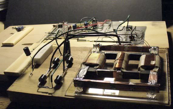
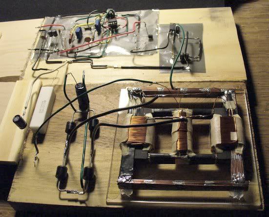
    The current system under construction is a prototype, therefore has not yet
    met with a finished appearance and may look a bit confusing in the video
    without prior understanding of how it is built.

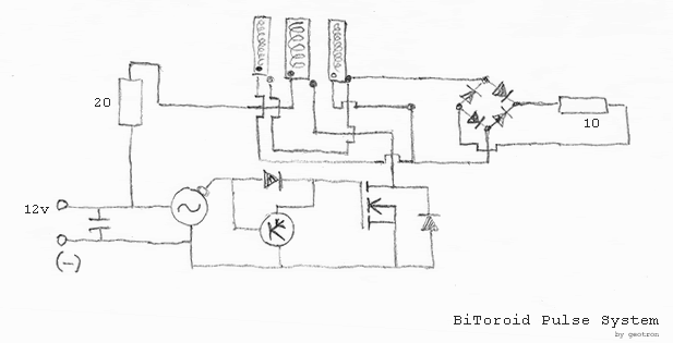
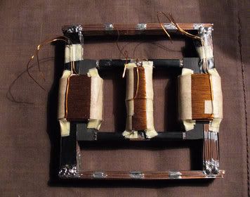
    The primary, center coil is fed by a 20ohm wirewound resistor, while the
    transformer core material is ferrite. The primary core is twice as thick
    as the secondaries, as may be somewhat apparent from viewing it, while the
    upper and lower E-Core center legs have been ground down to decouple the
    secondaries.

    The signal generator is a standard dual-555 pulsewidth modulator with the
    transistor hookup identical to how it is shown in the Desulfator schematic
    attached below.

    The secondary coils are connected to the bridge in parallel, start to start,
    end to end. Properties for each coil are as follows

    Primary: 77.8mH 2.0ohm
    Secondary 1: 222mH 3.2ohm
    Sec 2: 204mH 3.2ohm

    The observation I would like to share in the video is where the primary current
    is in comparison with the current being drawn through the two secondaries on
    load with a 10ohm resistor.

    While Thane Heins has shown an improvement in output of roughly 500%, this
    model does not perform to such a spectacular degree due to some reason that
    has yet to be revealed.

    Video: [ Bitoroid System Results ]

    Possible Reasons for Current System Performance

    -1- The thickness of the primary core is such that the secondaries
    prefer to draw magnetic flux from it instead of from eachother through
    the decoupling core legs?

    -2- The amount of core material removed by grinding away the center E-Core legs
    has not been sufficient to fully decouple the secondary coils?

    -3- The manner in which the secondaries are connected or oriented on their
    core legs is incorrect?
    Attached Files
    Last edited by geotron; 07-23-2011, 10:20 AM.

  • #2
    Schematic under construction, technical glitch encountered.

    Comment


    • #3
      Last edited by geotron; 07-23-2011, 11:05 AM.

      Comment


      • #4
        Hi geotron,

        I assume you use 4 ferrite E cores, the middle two E cores are turned into a closed magnetic path like in any normal transformer (one core's prongs face the opposing prongs of the other) and you bridge the upper and lower horizontal part of this closed core with the other two E cores whose middle thick legs were ground down.

        If this is so, than I do not think the ground down middle legs has any or even a very little effect on the overal operation because they are not really included in the magnetic path of the coils anyway, even if you had left those middle legs in place. The top most and the bottom most E cores I think has the effect of doubling the cross section area of the upper and lower horizontal parts of the closed center E cores, that is all.
        (you could consider the paralleled magnet paths as if you were to connect two electrical resistors in parallel to pass higher current in the common wires i.e. here more flux can pass into the right and left hand side columns of the middle E cores just because the magnetic reluctance got reduced in their top and bottom horizontal legs.)

        Regarding the current measurements: I would suggest two things.

        1) use at least a 470 or 1000 uF 16 or 25V electrolytic capacitor just between the other end of the 20 Ohm wire wound resistor going to the primary coil and the battery negative. I see there is a cap already in parallel with the DC input 12V at one side of this 20 Ohm, I say to use another such cap at the other side of this 20 Ohm.
        And insert the current meter between the direct +12V input and common points of your present cap shown and 20 Ohm (left hand side) leg. This way the DC input current could be measured with more certainty (cleanly, free from spikes) via the low pass filter (RC filter) formed by the two caps and the wire wound resistor.

        2) At your diode bridge DC output you do not have any capacitor for filtering the positive half waves produced by the bridge and your current meter may show false values. Just connect a 470 or 1000 uF 35 or 63V electrolytic cap right across the DC output of your diode bridge and then measure the output current into the load resistor.

        One more notice: If you measure input and output currents for power level comparison purposes, then you should consider voltages AND currents together both at the input and output , just comparing in and out currents is mostly meaningless. And the best is to filter the DC values so that the pulsed nature of such circuits should not lead you ashtray too much...

        Gyula

        Comment


        • #5
          Originally posted by gyula View Post

          I assume you use 4 ferrite E cores, the middle two E cores are turned into a
          closed magnetic path like in any normal transformer (one core's prongs face the
          opposing prongs of the other) and you bridge the upper and lower horizontal part
          of this closed core with the other two E cores whose middle thick legs were
          ground down.

          If this is so, than I do not think the ground down middle legs has any or even
          a very little effect on the overal operation because they are not really included
          in the magnetic path of the coils anyway, even if you had left those middle legs
          in place. The top most and the bottom most E cores I think has the effect of
          doubling the cross section area of the upper and lower horizontal parts of the
          closed center E cores, that is all. (you could consider the paralleled magnet
          paths as if you were to connect two electrical resistors in parallel to pass
          higher current in the common wires i.e. here more flux can pass into the right
          and left hand side columns of the middle E cores just because the magnetic
          reluctance got reduced in their top and bottom horizontal legs.)
          Hi Gyula, thanks for your response.

          You are correct, the cores are indeed as you say - four E cores altogether.

          The system has been upgraded to reflect your suggestions, with a 50v 100uF
          electrolytic between the primary and 20ohm resistor, and another in parallel with
          a 20ohm resistor acting as the load. It is my hope that these will suffice
          in place of the larger ones you have indicated.

          The results are captured on video in two parts,

          [ Comparison of Voltage on Primary Resistance with Load ]

          [ Current into Primary and Load Resistance ]

          Without a load resistor the output will charge its 50v capacitor up to more than 70
          in less than a minute. Upon last measure there was not more than 17v being generated
          from the anode and cathode sides of the bridge without any capacitor. The signal
          has the following properties -

          Frequency: 289Hz
          Pulsewidth: 11.4%

          All of the measurements thus far have been with this signal, while the system has
          been tested to produce upwards 65V from the standalone bridge (without a capacitor).
          This signal I've been using is the lowest the generator will produce to my knowledge
          with its current capacitor value.

          Possible Avenues to Proceed

          -- While measuring current draw into the primary and the load, increase the frequency
          to a greater measure in hopes that it will somehow resonate more efficiently and
          produce results more closely in line with what T.Heins has shown?

          -- Either insulate the center ferrite core leg material on the upper and lower parts
          or remove further material from them to expand the decoupling effect?

          -- Obtain a different transformer core structure with the secondary cores being
          thicker than the primary?

          Concerning this last idea, wouldn't it be more likely that the thickness of the
          horizontal legs connecting the primary core onto the secondary vertical cores hold
          more importance than the thickness of the primary core itself?

          Comment


          • #6
            Hi geotron,

            Thanks for your measurements.
            In my last post I mainly wanted to improve measurements to bring the measured data by the DMMs much closer to reality with my suggestions.
            (One notice to your voltage drop measured across the input 20 Ohm resistor: this can only serve as a check of the value to input current of course:
            I=0.4654V/20 Ohm=23.27 mA calculated, pretty close to the measured 23.13 mA, I mean this is a check only because your real input power to be considered is governed by the 12V DC supply and the duty cycle.)

            Now the main point is that in Thane's setup you referred to with the video link in your first post, there are an inner and an outer closed magnetic loops, as you surely noticed. BUT have you considered the reluctance of the two loops differ significantly? In the inner loop where his primary coil is placed, the core is made from a high reluctance material (meaning a core with low permeability) and the outer loop is made from a low magnetic reluctance core (meaning a high permeability material).
            So are your uppermost and lowermost E cores differ from the inner two E cores in the permeability values like Thane has it? (see this in his video it around 2.00 minutes)

            ALSO: there is still an difference in your setup wrt that of Thane, and IMHO this also could be a problem: the secondary coils in Thane's setup are wound onto BOTH cores, I mean here both the outer and inner cores which run in parallel and the secondaries embed BOTH cores, this is I think an important difference.

            Finally, one notice with Thane's input current measurement with the clamp-on current meter. He uses the lowest range on that instrument which happens to be 4 Amper, yet he measures with it as low as 0.003 Amper
            (3 mA). So I would definitely check this low current with another current meter with say 10 mA or 20 mA full scale range instead of the 4 Amper range.
            This is how I would show it in a video, that is all, I mean nothing negative.

            rgds, Gyula

            Comment


            • #7
              energy charging effect

              Without the resistive load in my previous video demonstrations, the input to the
              primary is showing to drop while energy is being funneled into the capacitor bank
              acting as the load.

              The figures are shown in this video - [ Single-Core BiToroid Cap Charging ]

              While the input floats around in the demonstration, the current into the 20ohm
              primary resistor without any capacitor on the load was .0037A, and it is not
              immediately apparent to me how the amount of energy being loaded into those two
              capacitors may be accurately compared to the current going into the primary.

              Providing there is an excess, it may be that a motor could be set up to obtain
              this energy from the caps into a coil while at the same time closing off the supply
              from the fullwave bridge in order to prevent loading the primary.

              -------------------------------

              Originally posted by gyula View Post
              Now the main point is that in Thane's setup you referred to with the video link in your
              first post, there are an inner and an outer closed magnetic loops, as you surely noticed.
              BUT have you considered the reluctance of the two loops differ significantly? In the
              inner loop where his primary coil is placed, the core is made from a high reluctance
              material (meaning a core with low permeability) and the outer loop is made from a low
              magnetic reluctance core (meaning a high permeability material). So are your uppermost
              and lowermost E cores differ from the inner two E cores in the permeability values like
              Thane has it? (see this in his video it around 2.00 minutes)

              ALSO: there is still an difference in your setup wrt that of Thane, and IMHO this also
              could be a problem: the secondary coils in Thane's setup are wound onto BOTH cores, I
              mean here both the outer and inner cores which run in parallel and the secondaries embed
              BOTH cores, this is I think an important difference.

              Well, you have indeed clarified things. The permeability of my primary core
              material is much to much! The dual-permeability secondary cores on Thane's system
              are now looking to be a challenge to adapt into this system I have built.

              If a number of high and low permeability ferrite rods were obtained, perhaps
              they could be peiced together in the following way, allowing the coils I have
              prepared for this non-working system to still be used. They are wrapped on
              board frames for easy removal.


              Then again what if a high reluctance core was designed for the primary out of
              a material like welding rod as is commonly used as a core in Bedini coils? Surely
              this metal would have a lower permeability than ferrite, but the questions remain
              as to whether the primary core must absolutely be shared with both the secondaries,
              and also how the primary portion of the E core ferrite would be removed.

              Summary of the Unknowns

              -- The manner in which ceramic ferrite core material may be effectively cut
              into peices?

              -- A source for the necessary low and high reluctance transformer core peices
              necessary to construct a working system?

              -- How the current setup is bogged down from a resistive load while seemingly
              non-responsive to a capacitive one, charging up without drawing current through
              from the primary?

              Comment


              • #8
                calculations and theory

                In light of my previous claim, here is a video showing the capacitive charging
                effect with a clear view on what happens to the primary current when the capacitors
                on load are switched on and off. The voltage on the bridge remains around 33V
                when they are switched off, different from my previous 17v figure and I'm uncertain
                as to why. Perhaps it is having the anode of the electrolyic caps connected
                while their cathode is on the switch.

                The way Heins has shown how his system reacts to a resistive load indicates
                much the same thing is happening... the input drops while the output goes up.

                --- Theory ---
                Due to the cores all having similar permeability, a resistive load will pull
                current through the primary while a capacitive load as demonstrated here will
                instead leave the flux paths to circulate freely and provide much the same
                effect as with a dual-reluctance system, loading energy into the capacitive
                resevoir from the secondary windings feeding themselves.
                ---------------------

                Video - [ BiToroid Capacitors on and off Load ]


                Could this be true?

                Comment


                • #9
                  Originally posted by geotron View Post
                  Without the resistive load in my previous video demonstrations, the input to the
                  primary is showing to drop while energy is being funneled into the capacitor bank
                  acting as the load.

                  Hi,

                  Yes, it shows normal behavior, an uncharged capacitor is a short circuit in the first moment of applying charge to it i.e. represents a heavy load on the output and this justifies the input current is higher when charging starts then it shows dropping as the charge gradually accumulates in the cap, till full charge up, an exponential process.


                  If a number of high and low permeability ferrite rods were obtained, perhaps
                  they could be peiced together in the following way, allowing the coils I have
                  prepared for this non-working system to still be used. They are wrapped on
                  board frames for easy removal.


                  Then again what if a high reluctance core was designed for the primary out of
                  a material like welding rod as is commonly used as a core in Bedini coils? Surely this metal would have a lower permeability than ferrite, but the questions remain as to whether the primary core must absolutely be shared with both the secondaries,
                  and also how the primary portion of the E core ferrite would be removed.
                  I agree with your drawing as a possibility, using flat ferrite cores, either from AM radio ferrite antenna rods or from the I part of the normal ferrite EI or UI cores. like these:
                  Ferrite EI cores
                  U/I Cores: Data Sheets - Ferrites and Accessories - Product Catalog - EPCOS AG
                  EI cores ferrite EI core EI-core work as power transformer cores power inductor cores

                  Perhaps you can find lower permeability "I" rods than your present E cores.

                  I think the secondary coils have to include both the low and high permeability cores, this is how Thane arranged his setup, no? He has some more videos on those transformers.


                  -- The manner in which ceramic ferrite core material may be effectively cut
                  into peices?
                  Ferrite cores are difficult to cut, they are bristle, see How to cut ferrite rod? - Wikianswers - Find and edit the best answers. How to? What? Is it? Can I? Where is?
                  Cutting ferrite rods - UK Vintage Radio Repair and Restoration Discussion Forum


                  Regarding the energy stored in a capacitor, you get the energy in Joule (Wattsec) from the formula. And the voltage difference must be taken as the difference of the squared voltages, not the voltages difference is squared. Also, you considered a single 470uF in the formula, while you have two such caps at the output?

                  So the energy in a cap when there is a max and min voltage from the charge up and discharge process:
                  E = C/2 x (V1^ - V2^)
                  C = capacitor in farads
                  V1 = maximum voltage of cap (before discharge)
                  V2 = minimum voltage of cap (after discharge)

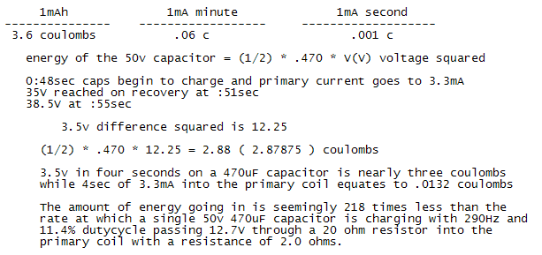
                  if V1=38.5V and V2=35V and C=2*470uF then E=0.00047*(1482.25-1225)=0.1209 Joule i.e. 120.9 mWsec.

                  Additions:

                  1) I do not get how you calculated 0.0132 coulombs for the primary coil, please explain.
                  (My take on the input power measurement is that if the supply voltage is 12V and the input DC current is 3.3mA, then the input power is 12*3.3=39.6 mW, in 4 seconds this is 39.6mW*4sec=158.4 mWsec energy taken from the battery.)

                  2) A more precise input power measurement could be done by running the setup from a charged up capacitor instead of the battery. Say you would charge up a 1000 or 2200 or 10000 uF capacitor to 13V (or 12.5V) and run the setup till the DC voltage goes down from 13V to 11V (or from 12.5V to 11.5V) in the input cap and also watch the output cap how it charges up during this time. The formula for the energy used from the input cap I showed above would be valid for the input cap too. This way the energy taken from the input cap could be simply compared to the energy received in the output cap if you wish this.
                  (Unfortunately, the electrolytic capacitors has a +/- 30 to 50% tolaration in their actual value and while their exact value could be calculated by measuring the charge up time via a known resistor, still their actual value remains the same during the tests of charging and discharging and their value as a multiplier in the formula remains always the same, hence no error in the comparisons.)


                  rgds, Gyula
                  Last edited by gyula; 07-26-2011, 06:33 PM. Reason: Addition

                  Comment


                  • #10
                    Gyula, many thanks for your helpful response.

                    Seeing as a Joule is 1A through 1ohm for 1 second and a Coulomb is also 1A
                    for one second, there ought to be a way to calculate these results differently.

                    The .0132 C figure you've made reference to is from taking ( 1mA/sec / .001C ) and
                    adapting it to the primary input current into ( 3.3mA/sec / .0033C ). Four seconds
                    of .0033 coulombs / sec is a total of .0132C

                    I agree with your results; the dimensions these coils will fit are 2x2cm on the
                    primary and 2x1cm secondaries, so by rotating the secondary coils 90deg on their
                    vertical axis there would be room for two 1sq scm ferrite rods of differing reluctance.

                    With this in mind, the parts list begins to grow.

                    Comment


                    • #11
                      variant design parameters

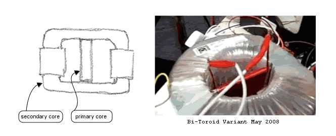
                      During a short break from this I have come across another [ Bi-Toroid video ]
                      posted by T.Heins demonstrating what is seemingly a better design by comparison
                      with the concentric toroid core as illustrated [ here ] previously.

                      Analysis of the design from what is shown on video has painted me the
                      following picture of how it could be operating with the dual reluctance
                      core materials. This variant seems of particular interest, considering
                      that its construction looks to be a magnifold less complex than the other
                      while its output is greater.


                      Its apparent construction leaves me fairly confident in pursuit of
                      replicating it, although I cannot claim to know its true form.

                      Looking to be about right?

                      Comment


                      • #12
                        Providing I've understood this variant from May 2008 correctly,

                        When the dual toroid structure is omitted, the primary magnetic flux would be
                        sharing the same path as the induced current from the secondary load... is there
                        some benefit gained unrelated to efficiency from having the primary core pass
                        through the secondary induced fields along with the low reluctance core?

                        Comment


                        • #13
                          Originally posted by geotron View Post


                          so that puts out about .2 volts then at 17 amp?

                          Comment


                          • #14
                            With a new system now in place, results are finally in.


                            [ Video - BiToroid Transformer Replication ]

                            120mV across 20ohm output with little if any change in primary 20ohm input.

                            The amount of energy being produced through the transformer is limited due
                            to losses encountered by the use of the component transformer materials. It
                            may be upgraded to allow a more efficient transfer of electromagnetic flux
                            by a different choice of primary insulator.


                            System Specifications

                            Primary - 5.3mH, 1.8ohm
                            Secondaries - 4.2mH, 2.1ohm

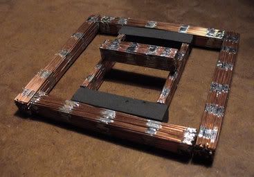
                            The primary core is built from er70s mild steel mig welding wire, while the
                            secondary cores are half resin-cast black iron oxide and half of the same mild
                            steel as the primary.

                            The signal generator is a dual 555 pulse width modulator, with a 20ohm wirewound
                            resistor into the primary. The secondary coils are connected in parallel onto a
                            rectangular fullwave bridge with 470uF capacitor and second 20ohm resistor.

                            Meters are connected to show the primary input and secondary output resistance
                            voltage drops while the system is put on load.

                            Currently open to suggestions on how to proceed... choice of materials, etc

                            Comment


                            • #15
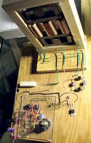
                              BiToroid Transformer with signal generator and mosfet pulsing components.
                              Secondary recovery positioned beside primary input resistor.


                              Comment

                              Working...
                              X