Announcement

Collapse
No announcement yet.

HF HV Phenomena Observations

Collapse
X
 
  • Filter
  • Time
  • Show
Clear All
new posts

  • #91
    Really fantastic work gentlemen!
    Im going to throw this link in on a grounding experiment.
    APRS SWER Test

    Comment


    • #92
      Originally posted by Farmhand View Post
      Cool, what are you using for the headset ?

      In Eric's drawing (the power one) it looks like the component near the terminal
      capacitance does a similar thing to the setup in drawing number 11. I tried a
      similar thing with an al. plate near the terminal of my LV setup and it did some
      strange things. But I'll keep my thoughts and observations about what it did
      to myself for fear of people thinking i'm a disinfo agent. Unless my
      opinion is asked that is.
      One of these things to listen through

      Crystal Earpiece : Earphones : Maplin Electronics

      Yes I think it's somehow changing the capacitance/resonance of the secondary (and extra coil in that case), or something like that. Also from the Colorado Springs notes Tesla does the same across the secondary only, not the extra coil. I haven't tried it that way yet in the normal HV setup, also I plan to try the small spiral with extra coil in this same crystal circuit to see if there are any differences. Apart from the obvious difference in frequency I expect the small coil to be a bit better because the wire is all glued in place so the layers aren't touching each other. The big coil is just a mess at the moment, so many kinks in the wire I ended up winding it as quickly as possible just to find out how much space the wire will take up on the base, and couldn't resist a test

      I bought a crystal radio kit (which includes a earpiece) a couple of months back because I was planning on getting into that stuff but hadn't got round to assembling it. So I'm using the 1N34 from that, and a second diode from my father's electronic project kit from the 50s. Early version of those 200 in 1 science project kit things. The variable capacitor also comes from the same kit It's pretty handy lol. It seems that two crystal diodes are required for it to work properly.

      You might be able to find some in an old TV or radio or something, maybe an old CRT monitor, I'm about to have a look. Also bought 50 of them from China this morning for £6. I'll be making a second crystal circuit tonight on another 200 in 1 science kit to have them both running side by side.

      I added a radiator pipe connection in parallel with the house earth and the reception got louder, it's definitely one station I'm hearing. They were playing this earlier, the first recognisable thing I've heard

      Starship - "Nothing's Gonna Stop Us Now" - ORIGINAL VIDEO - HQ - YouTube

      Maybe it's a sign

      Anyway through this simple thing I think I can see the importance of good earthing. I'll learn more about this once I get the second circuit up and running within the next couple of hours probably.

      Calculations sound good. I also have a few pages of a notebook starting to fill up with similar calculations. Based around 1 metre diameter secondary and overall wire lengths of 111m, 210m, 333m and 666m. 333m total = 111m secondary, 35-36 turns, 222m extra coil. Haven't calculated the size of that yet for 222m of wire. @70m secondary it would be 22 turns, 242 grams 22 SWG. 140m 484g extra coil = 140m/100 turns = 1.4m per turn = 44x44cm extra coil, 4.4mm wire spacing. The secondary wire could be double layered to make up the weight difference.

      I'd like to go with the 333m of total length first and see how it goes First though I'll have to find a space to put it I think
      Last edited by dR-Green; 01-14-2012, 02:04 AM.
      http://www.teslascientific.com/

      "Knowledge is cosmic. It does not evolve or unfold in man. Man unfolds to an awareness of it. He gradually discovers it." - Walter Russell

      "Once men died for Truth, but now Truth dies at the hands of men." - Manly P. Hall

      Comment


      • #93
        Originally posted by Iotayodi View Post
        Really fantastic work gentlemen!
        Im going to throw this link in on a grounding experiment.
        APRS SWER Test
        Interesting, thanks
        http://www.teslascientific.com/

        "Knowledge is cosmic. It does not evolve or unfold in man. Man unfolds to an awareness of it. He gradually discovers it." - Walter Russell

        "Once men died for Truth, but now Truth dies at the hands of men." - Manly P. Hall

        Comment


        • #94
          Hey dR, What do you think of think of this idea ? I'm not good with wood work.
          This is for the fence of the Colorado Springs coil model, 1:45 scale.
          The center of the coil is to the left of the side view of course, I didn't draw it very well.
          I'm thinking I will just drill a lot of holes instead of cutting grooves. I'll use the
          bigger round toothpicks and cut them neatly with a stanley knife we call them
          here. (box cutter) The toothpicks will hold the wires, I'll probably use 15mm x 40 or 50 mm wood.
          The toothpicks are almost 2mm diameter. Wow Might need to rethink that.
          I'm not confident cutting grooves so close together will work.

          The dowels to hold it to the base will be 6 mm. I'll make room for 2 turns of
          primary tube and 44 turns of secondary I hope, i'll see maybe less secondary
          turns.
          I'll make 12 of them I think maybe 16, I'll have to see about that too.


          Uploaded with ImageShack.us

          Nice work with the crystal sets too by the way.

          Thanks Iotayodi.

          Cheers

          Comment


          • #95
            Have you considered how many holes and toothpicks you will need? I think that might put you off woodwork for life When you said drill holes I thought you meant something else until I looked at the image...


            This might be an easier method and you end up with two bits Hmmm. Depending on the size of the holes you could use a very fine saw, and/or file down the resulting grooves to flatten them out or make them deeper. I might try that The job could also be made a bit easier by drawing out the markings along one long strip of wood so you'd only have to make one centre line and they should all more or less be equal.
            http://www.teslascientific.com/

            "Knowledge is cosmic. It does not evolve or unfold in man. Man unfolds to an awareness of it. He gradually discovers it." - Walter Russell

            "Once men died for Truth, but now Truth dies at the hands of men." - Manly P. Hall

            Comment


            • #96
              That's a good idea, but I don't think it will work in this case because I want a
              lot of slots close together and after cutting in half most of a small hole will be gone.
              I planned on making a template from metal to drill-cut or mark the holes/slots for
              a complete support.

              I have an idea also to use plastic 5mm thick 15 x 110mm and cut grooves in that
              and slot the face of the wooden support 5 mm deep to take the strip of plastic
              I can drill a small hole top and bottom sideways through the wood and plastic
              in the groove and pin them in place with wooden pins. (tooth picks)

              That's if I can work out how to use the router.

              They would be like moldings then too. The bendy MDF is looking good, I forget
              the distance between grooves of that, it might be too much for what I want.

              Thanks

              P.S. I've decided against the plastic, just cutting grooves in the wood will work, I think. Test piece worked well anyway.
              Last edited by Farmhand; 01-15-2012, 01:58 PM.

              Comment


              • #97
                Hi all, I've made the frame for the primary and secondary placed the primary
                loop and wound the secondary for my new Experimental coil.

                The resistance and inductance of the primary is negligible, the inductance of
                the secondary is 898 uH and it's resistance is 1 ohm.

                Here's a picture with one of my old coils in the center for size comparison.


                Uploaded with ImageShack.us

                I don't have the correct copper bolts yet so I used stainless steel ones for now.


                Uploaded with ImageShack.us

                Here's a video of a quick experiment, the small coil is 50 meters 150 turns 0.5 mm,
                the new secondary is about 50 meters 41 turns (including top turn) 1mm wire.

                I'm waiting on more wire for the extra coil.

                Experiment 24.wmv - YouTube

                Cheers

                Comment


                • #98
                  Hi all, Here's a few pretty picture's, at least now the ring of purple is at the top of the
                  secondary not the primary as with the other coil. This is only still only half the
                  coil, I haven't wound the extra coil yet. Just experimenting with the primary
                  circuit. I don't have any room to space the top turns any more than they are
                  unless I remove some turns. It's using between 60 watts and 90 watts
                  depending on things. I managed to reduce the voltage drop on the 12 volt
                  supply wiring from 2 volts drop to 1 volt I think I can get it better yet.


                  Uploaded with ImageShack.us


                  Uploaded with ImageShack.us

                  With the Earthed sphere pulled out of arc distance from the live sphere the
                  top wires really light up.


                  Uploaded with ImageShack.us

                  Here's a picture of the regulating/adjustment coil I made. A tradition Tesla
                  coiler would likely tap the primary itself, in Tesla's Colorado springs notes he
                  often experimented with a self induction box or regulating coil to tune the
                  primary. So I made this regulating coil, it works very well, I can change the
                  resonant frequency of the primary loop by almost 200 Khz from 950 Khz to
                  about 1150 Khz with it by tapping the different turns. I'm using 5.4 nF primary
                  capacitance at the moment. I'll post the circuit in an edit when I draw it up.


                  Uploaded with ImageShack.us

                  Disclaimer Those MOT's are not connected to the wall or the grid.
                  They are powered by a two phase inverter circuit (not a commercial one) and when short circuited they draw
                  only about 5 amps from the 12 volt source battery, which is strange because
                  when I use the setup the input current can be a lot more than the short
                  circuit current. Which I'm guessing is caused by the frequency and series
                  caps I'm using to drive the MOT's. When short circuited the MOT secondaries
                  must go out of tune and deliver less maximum current.

                  Here's the circuit I have at the moment.


                  Uploaded with ImageShack.us

                  Cheers

                  It occurred to me that since my primary negative is not grounded I should use
                  some safety gaps for over-voltage protection for the MOTs and maybe the
                  primary capacitors. I included two 3-4 mm safety gaps between the
                  secondaries and ground in the drawing, another from the primary cap positive
                  to ground might be good as well. There is one spark jumps the safety gap at
                  start up and shut off.


                  Uploaded with ImageShack.us
                  Last edited by Farmhand; 01-22-2012, 04:56 PM.

                  Comment


                  • #99
                    Hey everyone
                    Not to change the subject here, but I have been messing around and wanted to post, and here seemed like a good thread for it

                    I have been messing around with my Model T ignition coils again, and have finally figured out how to make them work!
                    no external switches needed, and they still light up neons and flo lights like a charm!
                    today, out of sheer curiosity, I put 24V through the primary, to see what kind of plasma I could make with them. @ 12V and 660mA I can get about a .5 inch stream of plasma. The contacts of the switching mechanism on top of the boxes will also arc like crazy, and emits a bright green glow, which I assume has to do with the copper they are made of burning....
                    When i used 24V (two 12V 7Ah batteries in series) I can actually get an arc hot enough to weld with, I fused two of my contacts together just a few minutes ago. Lots of cool stuff happens with the flo lights also, I can get dim light from them with just one wire, and if I move the other contact around the outside glass of the light, I can see a purple glow coming from inside where the other lead is touching the glass. I have gotten some purple flashing from my neon with this, and also can make a plasma arc that is nearly an inch long.
                    I know none of this is new to anyone else, but this is the first time I have been able to do many of these things to this degree. Been having a lot of fun with it last night and today, and figured I would share. I might take a video of it all later today, but for now I am letting things cool down for a bit. The top of the ignition box got a little hot, and stopped working for a few minutes, so once it all cools, I will be messing around with it again.
                    If I can get any video or photos, I will be sure to share them

                    Kind of makes me wonder how this thing would work hooked up to a tesla tower, or one of slider's mini towers. I can already tell there are some wireless effects at work here. My flo lights will light very dimly when they are near even one contact, even if it isn't touching the light directly. also, at one point, I had one of these boxes hooked up and running, and another one near it was also starting to make noise, with no power or wires connected to it what so ever.
                    Again, I know it's nothing ground breaking, but it's been a ton of fun to play with, and if I do find anything of particular interest, I will post it here

                    N8

                    Edit: 24V is too much power! After a bit of checking, I could see that the green glow I saw coming from the switch on top of the box actually cut through the metal, and that is why it quit working. If I am not mistaken, that means I more or less turned the ignition coil into a plasma torch... either way, pretty cool and a bit of a bummer at the same time. I am going to work with one of the other boxes I have, but be more careful not to damage this one, since I doubt I get any more to work with once these are gone.
                    Last edited by Neight; 01-30-2012, 12:31 AM. Reason: added info
                    The absence of proof is not proof of absence

                    Comment


                    • Hi Neight, Your very welcome to post here. I thought those Model T
                      coils were designed for 6 volts input. Maybe it is a good idea for you to build a
                      small Tesla coil and use capacitors and a spark gap to increase the voltage form
                      the Model T coils for experimenting, any attempt is a good place to start
                      because it will spark your interest even more (pardon the pun).

                      The big secondary above is a good example with only 40 turns it can change
                      1 or 2 thousand volts into 40 thousand volts. The two primary turns on it at the
                      bottom are used as one, they are in parallel, so on transformation alone (without resonant rise)
                      there should be a 1:40 transformation ratio, when resonant rise is a factor it can
                      be a lot more.

                      I think I have overvolted something in my setup, I have a feeling I've ruined
                      the insulation on the windings in my two MOT's by firing up the setup with the
                      MOT's not grounded while they were developing more than normal voltage,
                      Live and learn, I'll have to rescue another two or three of them from the
                      recyclers. They are practically free, but they are a bit dangerous.

                      When i get some more MOT's, or fix the problem whatever it is I'll post some
                      pictures and video of the setup. If I keep replacing stuff eventually I'll find the
                      problem and be able to avoid it better.

                      Cheers

                      Comment


                      • Here's some more pretty pictures,

                        Kinda looks like an electric flower.


                        Uploaded with ImageShack.us

                        Arcing it directly to ground drains the flower of it's Aura.


                        Uploaded with ImageShack.us

                        Bottom right hand corner the secondary is arcing upwards to a grounded cliplead
                        which somewhat diminishes the voltage at the top but not as much as I thought it would.


                        Uploaded with ImageShack.us

                        This is a 25 watt bulb between the secondary ground connection and the ground.
                        I estimate I'm only getting about 20 watt's max through the bulb and into the
                        ground. Or that is about the brightness, watts or whatever the photo makes
                        it look a bit brighter than it really is.


                        Uploaded with ImageShack.us


                        Circuit Picture
                        Here's a link to a more recent pic of the setup downstairs, I used some double
                        insulated HV silver looking wire it's only 3 Kv but some 10 Kv stuff is on the
                        way, and I also upgraded to two bigger MOT's, I've worked out that I had
                        problems with diodes and capacitors, now i'm using a circuit with no diodes.
                        I ordered some 30 Kv rated polystyrene capacitors, they were the cheapest
                        HV caps I could find for the size in nF.

                        Here's a sketch of the whole setup from battery to TC. I think it's correct.
                        Input for the above photo's was about 7 amps at 12 volts.


                        Uploaded with ImageShack.us

                        Here's a link to a video from a few days ago with the same circuit but running from only 120 volts and with only 8 nF or so primary capacitance.

                        Series caps dual spark gaps.wmv - YouTube

                        Last edited by Farmhand; 02-07-2012, 04:18 PM.

                        Comment


                        • Originally posted by Neight View Post
                          Hey everyone
                          Not to change the subject here, but I have been messing around and wanted to post, and here seemed like a good thread for it

                          I have been messing around with my Model T ignition coils again, and have finally figured out how to make them work!
                          no external switches needed, and they still light up neons and flo lights like a charm!
                          today, out of sheer curiosity, I put 24V through the primary, to see what kind of plasma I could make with them. @ 12V and 660mA I can get about a .5 inch stream of plasma. The contacts of the switching mechanism on top of the boxes will also arc like crazy, and emits a bright green glow, which I assume has to do with the copper they are made of burning....
                          When i used 24V (two 12V 7Ah batteries in series) I can actually get an arc hot enough to weld with, I fused two of my contacts together just a few minutes ago. Lots of cool stuff happens with the flo lights also, I can get dim light from them with just one wire, and if I move the other contact around the outside glass of the light, I can see a purple glow coming from inside where the other lead is touching the glass. I have gotten some purple flashing from my neon with this, and also can make a plasma arc that is nearly an inch long.
                          I know none of this is new to anyone else, but this is the first time I have been able to do many of these things to this degree. Been having a lot of fun with it last night and today, and figured I would share. I might take a video of it all later today, but for now I am letting things cool down for a bit. The top of the ignition box got a little hot, and stopped working for a few minutes, so once it all cools, I will be messing around with it again.
                          If I can get any video or photos, I will be sure to share them

                          Kind of makes me wonder how this thing would work hooked up to a tesla tower, or one of slider's mini towers. I can already tell there are some wireless effects at work here. My flo lights will light very dimly when they are near even one contact, even if it isn't touching the light directly. also, at one point, I had one of these boxes hooked up and running, and another one near it was also starting to make noise, with no power or wires connected to it what so ever.
                          Again, I know it's nothing ground breaking, but it's been a ton of fun to play with, and if I do find anything of particular interest, I will post it here

                          N8

                          Edit: 24V is too much power! After a bit of checking, I could see that the green glow I saw coming from the switch on top of the box actually cut through the metal, and that is why it quit working. If I am not mistaken, that means I more or less turned the ignition coil into a plasma torch... either way, pretty cool and a bit of a bummer at the same time. I am going to work with one of the other boxes I have, but be more careful not to damage this one, since I doubt I get any more to work with once these are gone.
                          Hey Neight, I decided I wanted to mess with some coils and vibrating
                          switches too. So I made one. This is just a prototype to see some things
                          and gather some data, I'll make one with a whole bunch of turns for a
                          secondary and a primary of about 50 turns maybe less, depends on how i do
                          it.

                          Here's a video of the first go, this coil is only about 3.5 mH not sure of the
                          turns less than 250 I think. I noticed the frequency of this setup is about 200 Hz
                          with 6 volts and about 450 Hz with 12 volts.

                          Big relay.wmv - YouTube

                          This is lighting a 5 watt bulb from the field collapse. There is a bulb in that ball
                          of light somewhere.


                          Uploaded with ImageShack.us

                          This is a basic sketch of how I did it.


                          Uploaded with ImageShack.us

                          It's really quite a fun project and I will definitely be trying to build a much better and more powerful one. It's kind of just a big reed switch principal.
                          I might use something like this as part of a receiver to act as a relay.

                          Cheers

                          P.S. Neight do you have any video of the Model T vibrating switch working, I
                          would like to see that, it would be helpful.

                          ..
                          Last edited by Farmhand; 02-08-2012, 05:36 PM.

                          Comment


                          • Originally posted by Farmhand View Post
                            Hey Neight, I decided I wanted to mess with some coils and vibrating
                            switches too. So I made one. This is just a prototype to see some things
                            and gather some data, I'll make one with a whole bunch of turns for a
                            secondary and a primary of about 50 turns maybe less, depends on how i do
                            it.

                            Here's a video of the first go, this coil is only about 3.5 mH not sure of the
                            turns less than 250 I think. I noticed the frequency of this setup is about 200 Hz
                            with 6 volts and about 450 Hz with 12 volts.

                            Big relay.wmv - YouTube

                            This is lighting a 5 watt bulb from the field collapse. There is a bulb in that ball
                            of light somewhere.


                            Uploaded with ImageShack.us

                            This is a basic sketch of how I did it.


                            Uploaded with ImageShack.us

                            It's really quite a fun project and I will definitely be trying to build a much better and more powerful one. It's kind of just a big reed switch principal.
                            I might use something like this as part of a receiver to act as a relay.

                            Cheers

                            P.S. Neight do you have any video of the Model T vibrating switch working, I
                            would like to see that, it would be helpful.

                            ..
                            Hey Farmhand
                            These things are quite a bit of fun to play around with, and I have been thinking about trying to build my own as well. There is a video I posted a little while back that shows a lot of what they look like inside. From what I have seen in them, I am sure they are made of one power wire, though I have no idea how many turns, not too many from what I can see of the wire through whats left of the tar-like substance they are filled with. They have two blocks of secondary winding, in series with each other, and they use a really really fine wire for the secondary, loads of turns, I wouldn't even guess at how many.
                            here is the link to the video -
                            Model T power.... - YouTube

                            I will take a new video now that I actually have the built in switch working, though the results are the same as what I was able to do with the reed switch and relay switches from my previous posts. These things are really loud, and the switch contacts spark quite a bit, and with 24V input, I was getting one to start burning the copper and making great green sparks! I can get some one wire lighting with them, on 22w fluorescent and can even get them to light a neon with one wire, though not very bright.
                            I have also experimented with them and my SSG. I saw a video of Lidmotor using a modern ignition coil in series with the negative output on a standard SSG and getting it to light fluorescent lights with them and also getting to charge another battery off with a diode off the ignition coil. I didn't get as good of results as what lidmotor got, though I did get it to work. I would light fluorescent light bulbs, though the lights had to be off to see it light :/
                            It would also light a neon very dimly.

                            There was one other circuit I found and tried, though I would have to find it again to remember where on the forum it is... It put the ignition coil across the pos of the run battery, and (if I remember correctly) the collector of the transistor. I could get the SSG coil to self resonate, and light both the fluorescent and neon visibly, though it wasn't all that bright. Oddly, the SSG coil would drive the ignition coil when the rotor magnets past, but it wouldn't drive the rotor. I couldn't get it to spin for anything, but the lights would flash when the magnets pass the core.

                            These will eat some current though, up to 1.5A from a 12V source. I couldn't tell if it loaded the motor, cause it wouldn't run. With the ignition coil in series with the negative, the motor would run, and I didn't notice any load on the motor, or power draw of the SSG. It actually did seem to help with charging the battery though, the voltage climbs noticeably faster. I was also able to get it to charge an additional battery through the ignition coil in this circuit as well.

                            Sorry I got so long on here, but that is pretty much everything I have done with them since my last post

                            I have to work today, but I will take a video showing some of the more interesting things I have done and post it up here this weekend. Thanks for letting me know you are building this, I am interested to see how it goes, and perhaps help me figure out how to build one myself, that much faster
                            The absence of proof is not proof of absence

                            Comment


                            • Pretty nice video on those T coils. I've been playing with them for some time now, on and off, they are quite interesting. I found some old drawings on them and they are wound CW-CCW on the secondary coils with a total of 16000 turns and the primary has 212 turns making it around 75:1.

                              If you remove all the contact hardware you can use this to run your motor wheel by positioning the core on the wheel and the by product is HV output on the secondary.

                              I'm looking for more of them as I only have a couple right now that I've been playing with various projects. Great little experimental inductors !

                              Fun stuff !

                              First time I visited this thread, your doing some amazing stuff Farmhand - great work !

                              Comment


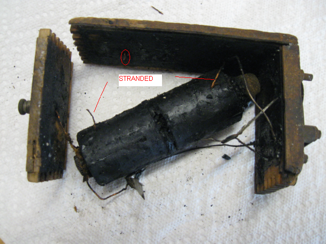
                              • Heres one I tore apart awhile back. The fine wire on mine is stranded with 4 to 6 strands. It was hard to see even with a magnifying glass as to the amount of strands. Hard to separate with the tar on it. My guess was between 30 to 32 gauge wire. It was tied in to both the primary and secondary terminals.

                                Comment

                                Working...
                                X