Announcement

Collapse
No announcement yet.

HF HV Phenomena Observations

Collapse
X
 
  • Filter
  • Time
  • Show
Clear All
new posts

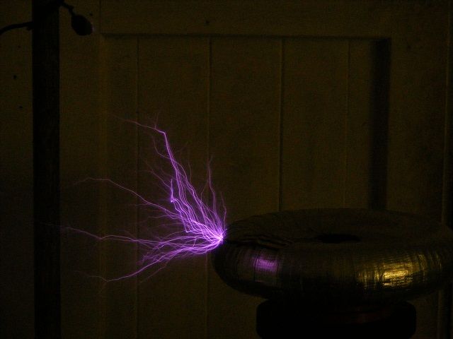
  • Here's my first attempt at some Morse code, my keying is probably all wrong.
    There is a message in there, is my Morse understandable ?

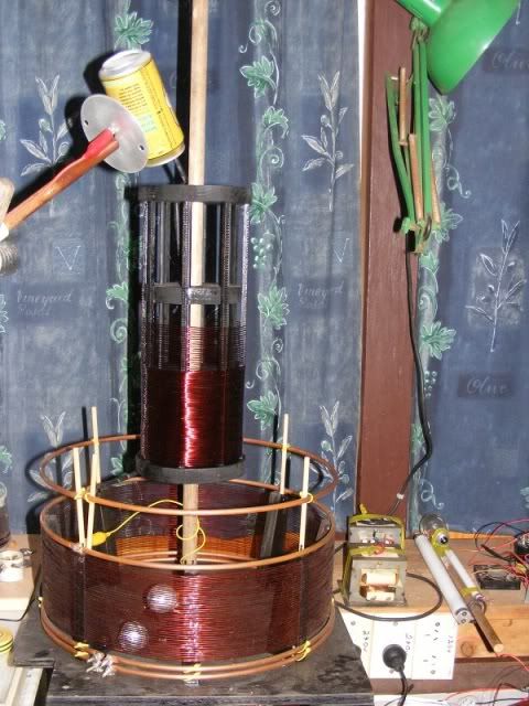
    Doing this has given me some idea's for ways to use something similar in
    connection with HV. I put these parts together so I could see and hear the
    keying and practice. There is no real rhyme or reason to the configuration
    except that it works a speaker and a light by keying.
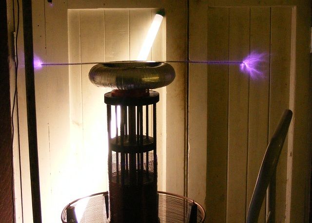
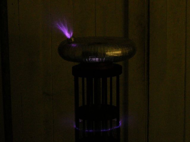
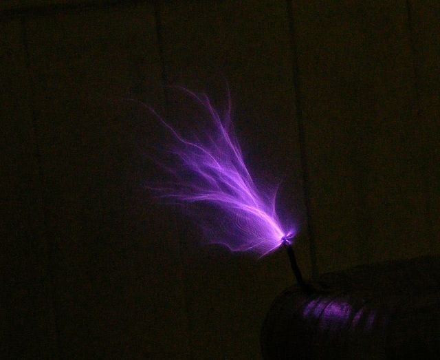
    Video of message.
    Morse message.wmv - YouTube


    Uploaded with ImageShack.us

    If someone that knows Morse Code can understand my message please let me know ?

    Cheers

    Comment


    • Ok, I finally have my video of the model t ignition coil working.
      I have been trying to upload this video for two days now, and for some reason my usual method of upload just wouldn't work. I finally got it to load up, so I can finally post the link to it

      M T ignition coil for Farmhand (part 1) - YouTube

      This video is part one, though only the beginning of the video shows the model t coil in action. The rest of video one, and all of video 2 I made just to show some of the things I have been posting here on the forum. The second video is still uploading, but should be available in the next 10 mins or so.
      Of course, things wont work for me in the video like they do without the camera running, but you get the idea of what I am trying to show.

      Hope all that makes sense, and I hope the video is useful to your project Farmhand

      I really enjoyed the video of the morse code, and I am planning on taking some time to translate the message in it, so I know what you are saying.

      I will be doing some more tests with these ignition coils, and will keep updating as I find anything useful or just plain cool

      N8

      Ok second video is up and running on my youtube channel if anyone is interested.
      I actually shot most of what is posted twice, since the first video wouldn't upload, I though there might be a problem with the video itself. There were a few things I forgot to mention in the second filming....
      One interesting thing I noticed with the modern ignition coil test, is it will wirelessly effect my wireless mouse! I had a few of the alligator leads near my mouse, but not touching it in any way, and when I moved my hand through the induction field, I noticed the computer screen would scroll all by itself. I was able to get it to just move on it's own depending on where I put my hands near the circuit. This was a pretty big surprise, as none of my experiments have ever effected my computer equipment.
      another Thing I forgot to mention, when the DMM was hooked up to the run battery in my second video, and the coil wouldn't self oscillate, not only did the power draw lower on the input to the SSG, but the more lights I hooked up to the secondary of the ignition coil, the lower it would drop the power draw also. I actually got my SSG down to 80mA draw and had 3 neons and 4 fluorescent lights hooked up to the ignition secondary, all with the rotor spinning about as fast at that particular rotor will go with 12V input.
      I would like to find a way to oscillate the ignition coils at a much higher frequency that the SSG will do, and see if that will boost the wireless lighting and one wire lighting effects to a noticeable degree. I am also planning on trying to make a mini tesla coil with one of these ignition coils, though I need to find or build a HV cap for it, and a secure adjustable spark gap. The more I learn, the more excited I get. I am also thinking of running the power through a joule thief or joule ringer, and seeing just how low I can get the input power and still get big HF HV output to run lights. I seem to be long on ideas and short on experience right now, but I am learning as much and as fast as I can.
      Last edited by Neight; 02-12-2012, 03:48 PM. Reason: added some info
      The absence of proof is not proof of absence

      Comment


      • Hi Neight, Thanks for taking the time to do that for me, I appreciate it. Looks
        like I will need to definitely continue to use car points so there is some
        reliability. Looks like the Model T vibrator is louder than mine because the
        T coil has a flexible vibrator arm where as mine has a pivot and spring. Also
        mine can work without the attracted arm actually touching the core, not that
        the noise would bother me.

        I watched both video's, good to see you enjoying your experiments. You
        experiment in the wee hours too hey, that's when I like to experiment, I would
        prefer to be woken from sleeping than be interrupted during an experiment

        Between midnight and daylight there is very little chance of disturbance here
        and with no interruptions I can concentrate better and let the free thoughts
        happen.

        Last night I discovered another simpler way (simpler for me anyway) to get a
        gating effect on the signal pulse train for driving transistors. I found after
        studying the SG3525 PWM datasheet for a bit that if I apply a positive pulse
        to the shutdown pin (pin 10) it will stop the pulses very well, this chip has the
        problem of a soft start feature but it still works ok if the soft start cap is small
        enough or I think big enough will work too. This method seems to give an
        almost instantaneous shutoff of the outputs even half way through a pulse,
        not sure if that might cause problems yet.

        With this method I can blank the drive pulse for a variable period at a variable
        frequency so I could do say groups of pulses at 90 Hz with pauses of a
        fraction of a second at 60 hz intervals, then my spark gap could work in
        bursts of HF firings at 60 hz with variable pauses. Which should create a kind
        of 60 Hz beat. This method seems to be more flexible than the other method I
        used previously.


        Uploaded with ImageShack.us


        Uploaded with ImageShack.us

        Thanks again Neight, much appreciated.

        Cheers

        Comment


        • Originally posted by Farmhand View Post
          Hi Neight, Thanks for taking the time to do that for me, I appreciate it. Looks
          like I will need to definitely continue to use car points so there is some
          reliability. Looks like the Model T vibrator is louder than mine because the
          T coil has a flexible vibrator arm where as mine has a pivot and spring. Also
          mine can work without the attracted arm actually touching the core, not that
          the noise would bother me.

          I watched both video's, good to see you enjoying your experiments. You
          experiment in the wee hours too hey, that's when I like to experiment, I would
          prefer to be woken from sleeping than be interrupted during an experiment

          Between midnight and daylight there is very little chance of disturbance here
          and with no interruptions I can concentrate better and let the free thoughts
          happen.

          Last night I discovered another simpler way (simpler for me anyway) to get a
          gating effect on the signal pulse train for driving transistors. I found after
          studying the SG3525 PWM datasheet for a bit that if I apply a positive pulse
          to the shutdown pin (pin 10) it will stop the pulses very well, this chip has the
          problem of a soft start feature but it still works ok if the soft start cap is small
          enough or I think big enough will work too. This method seems to give an
          almost instantaneous shutoff of the outputs even half way through a pulse,
          not sure if that might cause problems yet.

          With this method I can blank the drive pulse for a variable period at a variable
          frequency so I could do say groups of pulses at 90 Hz with pauses of a
          fraction of a second at 60 hz intervals, then my spark gap could work in
          bursts of HF firings at 60 hz with variable pauses. Which should create a kind
          of 60 Hz beat. This method seems to be more flexible than the other method I
          used previously.


          Uploaded with ImageShack.us


          Uploaded with ImageShack.us

          Thanks again Neight, much appreciated.

          Cheers
          No problem Farmhand, I am happy to help in any way I can!
          I have never used any PMW's or anything with more than 8 pins on it (only used a few 555 timers and opti-iso chips at this point)
          It sounds like you are getting some interesting results with it though, and I really like the idea of a 60hz "beat", sort of a pulse for HV circuits.

          And I agree with you, the "wee" hours are by far the best quiet time to work in. I work a 12 hour shift several nights a week, so I am up until daylight pretty much every day anyway...
          I am also the same as you in the fact that I would much rather be bothered from sleep than from my experiements. I get so wrapped up in what I am doing on my workbench, people often get a bit put off that I am ignoring them It's not intentional, but I just can't help myself, this kind of work is so interesting, and I am very driven to keep it going!

          I started looking into joule thief circuits, and have built 2 so far. I am really impressed with these simple and highly effective circuits! I have been leaving one run for over 24 hours now with one LED lit and a secondary AA battery charging, and the charging has been a dead even 1:1 and the circuit has drawn a steady 50mA without variation all night.
          The second one I built is actually Lasersaber's super joule ringer, and it did some pretty interesting things before I shorted something out and burned up my primary coil. I was using a very small toroid with 20 bifiler primary turns for the center tap, and my secondary was one layer of 30AWG magnet wire filling up the rest of the toroid. with 12V input from a 7Ah battery, I could get a neon to light with a distinct purple haze around the contacts, which I have never seen before in my own experiments. it also lit a 22W fluorescent bulb very brightly, nearly to full brightness!
          I think my coils were too small for the input power and it burned off some of the insulation and shorted my circuit. I plan to add some turns on the secondary, rewind the primary (the one that burned up) and try it again with smaller power, maybe 9V input, or even 6V from a wall wart.
          rebuilding should only take me an hour or so, and I hope to have some more results to share in the next few days (got a busy week this week with work and V-day wife activities )
          I did post a short video on youtube of one of the LEDs i was lighting with the joule thief. It was a 7 color LED that could flash or be steady on, and when I put the secondary battery in series with it to try and charge it, the LED started flashing through it's 7 colors. It made for a neat little light show, so I put it up. Nothing fancy, but fun to watch
          here is the link for anyone interested
          Joule Thief Light Show - YouTube
          again, this is not experimental, nor are there any new discoveries, or even HV to speak of, just a plan joule thief and a pretty cool LED that I thought was neat enough to share
          If I can get my super joule ringer back up and running, I will take some video of the neon glowing bright with a purple aura, and will share anything else I find out with it also.

          N8
          The absence of proof is not proof of absence

          Comment


          • I nearly forgot, why I even started talking about the joule thief in this thread in the first place...
            I found a video, and maybe it's only new to me and you guys will already be familiar with this technique, but it got me excited to try it.
            here is the link
            How to make a joule thief super high voltage fly back transformer driver - YouTube
            This kid does some pretty amazing stuff with a joule thief on a flyback transformer. the video is worth a watch for sure, and I have a few flyback transformers I could work with. This is something else I am planning to build in the near future, though it may have to wait until next week, as this week is pretty well covered up already.
            if this is nothing new to you guys, sorry for the time killer, but if it is new, I hope its as entertaining for you as it was for me
            enjoy

            N8
            The absence of proof is not proof of absence

            Comment


            • Here's a short video of some tests.

              Capacitive rings test.wmv - YouTube

              Cheers

              Comment


              • Hi all here's a picture or two of my larger transformer, before anyone thinks
                the wrong thing, I must say the what I have done here should in no way
                reflect on what Mr Dollard is doing, this transformer I have built using
                information from several sources mainly Tesla, though I have used some tips
                from Eric.

                This setup was well and truly under construction well before Eric posted the
                designs for his setups, I am modeling it after the Colorado Springs coil and
                even taking similar steps in the design experiments, hence the 40 turn
                secondary still has not been changed to a 20 turn coil of double conductor. If
                the dates are checked it can be seen I posted pictures of this secondary well
                before Eric posted his designs. I'm only saying this to show I can read the
                Notes and understand them in my own way, and I don't want people to come
                along and say Eric this Eric that, you just copied Eric's design. The design I
                tried to copy is the design of the Colorado Springs notes, to a degree.

                I mainly want to state that any failure I have should not reflect on Eric but on
                the flip side any success should not be credited to him either really. I have
                differing opinions to Eric on a few points. The thing is I'm damned if I do and
                damned if I don't. If I give credit to Eric for some idea or whatever I will just
                be told I misunderstand and am spreading disinfo, but if I don't give credit to
                Eric for using an idea or something I think he came up with then I will probably
                get told I am copying his work and not giving him credit for it while getting it
                wrong at the same time. This is how it is, Eric does not own Tesla's work and
                he does not have dominion over who does what. I can do what I want to do
                without all the numbers and "letters that are not part of words". I have my
                own simplified theories of how what I do and want to do will work, based on
                what I've learned form many sources. I make no claims except to claim I have
                done what I have done when I have done it.

                Ok the practical implementation of the cap rings and beer can idea are Eric's,
                the rest is pretty much my implementation of what I've gathered from the
                Colorado Springs notes, including the primary circuit and the use of a reg coil
                in the primary circuit.

                Just sitting turned off. with the beer can on there are no real arcs to see
                anyway just some small leaks. Frequency is just over 1 Mhz. Input is about 85 - 95 watts.
                The terminal can shock me through a 10 inch fluro and along a few inches of wood.


                Without the beer can.


                When I put a 25 watt bub in series with the ground connection it lights right
                up and also arcs inside the bulb. When I use a higher capacitance on the top
                there are arcs between the rings at the supports with the rings 50 mm apart,
                they are at 60 mm apart now.

                Cheers

                Comment


                • Amazing

                  Hi Farmhand,

                  amazing experiments you are doing, i wish i had more time on my hand to join.

                  Concerning the morse code experiment; not bad at all for a first time.
                  And i agree with your message, they are everywhere!

                  Regards Itsu

                  Comment


                  • Getting there

                    Hi Itsu, I'm working a lot more slowly now because of regular duties of life. I
                    think I have worked out the tuning required for these three coil systems,
                    when the third coil (extra coil) is added, if it is not tuned to the correct
                    frequency close enough there is very little output into the ground, I found
                    that the extra coil needs to be (with it's terminal capacitance) the same
                    frequency as the secondary or an odd multiple of it. The higher the frequency
                    is the harder it is to match the secondary and extra coils resonance of
                    course. The way I have it now they are the same frequency and if I join the
                    cap rings the setup seems to work a bit better.

                    It is kind of amazing how it can still work with over 60 mm gap between the cap rings.

                    The Morse code message was fairly easy, I just wrote the message out
                    vertically and put the Morse code for each letter beside the English letter,
                    then I just key the letters from to bottom with small spaces between the
                    letters and bigger ones between the words.

                    Cheers

                    Comment


                    • More fun with Tesla coil. I've made a rotary spark gap and changed to a DC
                      primary circuit using two MOT's with a resonant charging circuit to increase
                      the discharge voltage to the primary. It's good for a few hundred Watts.

                      The main object of this coil is not to produce arcs, but it can do small ones
                      even with only 164 turns in the secondary circuit.

                      Video clip with rotary spark gap
                      Up to 800 BPS - YouTube


                      And this is the discharge from when the primary circuit was AC.


                      Cheers
                      Last edited by Farmhand; 11-07-2012, 11:19 PM.

                      Comment

                      Working...
                      X