Announcement

Collapse
No announcement yet.

3D electromagnetic field

Collapse
X
 
  • Filter
  • Time
  • Show
Clear All
new posts

  • #46
    Originally posted by tutanka View Post
    Caduceus coil = Tesla coil

    Nothing of new...
    Could you be more explicit, remember that not everyone is as familiar as you seem to be with 3d electromagnetic theory...

    forget the math, try explaining it in layman terms, as Mike does
    Signs and symbols rule the world, not words nor laws.” -Confucius.

    Comment


    • #47
      I'm currently reviewing THE STUBBLEFIELD PAPERS

      you can find it here: http://www.energeticforum.com/144162-post23.html


      Note: check quantumuppercut proposed coil in http://www.energeticforum.com/150951-post1134.html
      Last edited by MonsieurM; 08-10-2011, 01:45 PM.
      Signs and symbols rule the world, not words nor laws.” -Confucius.

      Comment


      • #48
        Originally posted by mk1 View Post
        This is my caduceus pickup coil ...

        ‪Mk1 Pickup Winding .‬‏ - YouTube
        thank you mk1 for the Caduceus coil test
        Signs and symbols rule the world, not words nor laws.” -Confucius.

        Comment


        • #49
          I have stumbled across some internet pages where the term caduceus was used to actually refer to a series bifilar cancelling coil on one core with 2 wire wound next to each other all the way and connected at one end.
          They both perform differently.
          The series bifilar cancelling coil picks up no magnetic field. At least there is no in-phase currents across it. Whether or not there is 2 180 degree out-of-phase currents perfectly cancelling occuring, i can not answer since i can't measure it.
          It does however pick-up an electric field (my assumption)/ or even EH field like an antenna, and turns it into output.
          Just the coil itself with a ferrite core,no Tate voltage doubling or anything.
          While sitting in the kitchen attaching a voltmeter to that tiny test bifilar coil i was getting 0.6 Volt readings, which surprised me.
          Since i could not understand this reading, i moved with that whole set-up through different rooms and noticed the reading dropped to zero.
          I traced the source of the energy to be the neon-lamp on the kitchen ceiling. So probably the E-Field of that neon transformer caused the interference.

          EDIT: I don't like to report wrong facts, so i was repeating that neon lamp experiment again and found out that the coil
          does not seem to output anything by itself near the lamp.
          The effect of the 0.6 Volt come solely from the bridge rectifier that i used to measure the voltage even with no coil attached.
          Makes a nice antenna that rectifier hehe. So sorry for attributing the ability to output in-phase current due to EM field to the bifilar coil, it is not the case.


          With the real (Smith) Caduceus coil i also have been able to use them as generator coils, so it picks up magnetic field energy, like Mk1 is showing.
          For the record, neither type is being used By Romero (should someone come to the idea to project that into his coils)
          Last edited by Xenomorph; 08-10-2011, 07:01 PM.

          Comment


          • #50
            Originally posted by Xenomorph View Post
            I have stumbled across some internet pages where the term caduceus was used to actually refer to a series bifilar cancelling coil on one core with 2 wire wound next to each other all the way and connected at one end.

            With the real (Smith) Caduceus coil i also have been able to use them as generator coils, so it picks up magnetic field energy, like Mk1 is showing.
            For the record, neither type is being used By Romero (should someone come to the idea to project that into his coils)
            from THE STUBBLEFIELD PAPERS

            Signs and symbols rule the world, not words nor laws.” -Confucius.

            Comment


            • #51


              Hmm, this is basically the Floyd Sweet approach with the conditioned magnets. And that process isn't as simple as the author describes.
              Only a handful of people ever got a magnet to oscillate and no-one except Sweet ever had one oscillating for longer than a week or so.

              Sweet released a lot of disinfo, it might even be that the magnet conditioning was a distraction too.
              A shot of the "real" Sweet device i posted on page 1 of this thread, it is about making use of a magnetic fields in more than one plane.
              So the coils are like a caduceus connected at a node point, but at a 90 degree angle surrounded by an aluminum container.

              But if you ever end up with a "conditioned" magnet, let me know
              Last edited by Xenomorph; 08-10-2011, 09:00 PM.

              Comment


              • #52
                I raise you then with a myers absorber (same source: Nathan B. Stubblefield 1860 - 1928 )

                THE STUBBLEFIELD PAPERS


                note: the role of cardinal points in the set up

                from: http://www.eh-antenna.com/EH_maxwell.pdf

                All this demands we consider any physical processes as occurring in an external electromagnetic field....
                ...in the universe there is no motionless point, and uniform, rectilinear movement in the pure state does not exist.
                Last edited by MonsieurM; 08-10-2011, 09:14 PM.
                Signs and symbols rule the world, not words nor laws.” -Confucius.

                Comment


                • #53
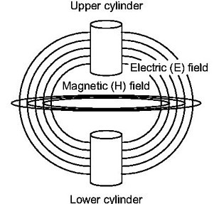
                  try to include 3d electromagnetic theory when viewing the image


                  as a comparison Felix Ehrenhaft: Magnetic Current


                  Signs and symbols rule the world, not words nor laws.” -Confucius.

                  Comment


                  • #54
                    Looks easy enough to build. Has anyone built it?
                    I am out of materials to attempt it at the moment.
                    Doesn't look like it would have huge gains though.
                    To make sparks, you can even use a Joe Tate device.
                    That makes no statement about huge energy gains.

                    Comment


                    • #55
                      Originally posted by Xenomorph View Post
                      Looks easy enough to build. Has anyone built it?
                      I am out of materials to attempt it at the moment.
                      Doesn't look like it would have huge gains though.
                      To make sparks, you can even use a Joe Tate device.
                      That makes no statement about huge energy gains.

                      Let's get familiar with it (the theory that is ), then we will play with it

                      ps: have you thought of investigating the use of the cardinal points has any effects on the "real" Sweet device"
                      Last edited by MonsieurM; 08-10-2011, 09:40 PM.
                      Signs and symbols rule the world, not words nor laws.” -Confucius.

                      Comment


                      • #56
                        Originally posted by MonsieurM View Post
                        Let's get familiar with it (the theory that is ), then we will play with it

                        ps: have you thought of investigating the use of the cardinal points has any effects on the "real" Sweet device"
                        Well it seems to be a magnetic cancelling point like in a Smith caduceus coil.
                        A bit hard to investigate the fields in such a set-up, i lack the necessary equipment. But i have a faint idea of what is going on in the device.

                        Comment


                        • #57
                          Sorry about my explination of coil

                          Sorry for the bad explination of the coil setup, I will try again

                          Wind a bifiler coil, the start of one wire will be 1s and the other 2s, the finish ends will be 1f and 2f. Now connect 1s and 1f together and 2s and 2f together. what you have made is two coils with a capacitance built in joining them together. We do not want an antenna, we want a magnetic coil with a vortex field and this is one way to do it.

                          If I have time I will wind one. Trying to finish my new lab and office.

                          Remember that the only connection of one coil to the other is one of capacitance, it is an LC circuit with low R depending on the wire used.

                          Mike

                          Comment


                          • #58
                            OH ! thanks Mike for the explanation.
                            So that's basically 2 shorted coils, closely coupled together, on a single core.

                            But if they are shorted, what will define the direction of current in each, so that the counter-wind effect can produce the vortex ?

                            I'm afraid I still haven't understood what you mean. As I see it, this will create a 1:1 transformer that has its windings shorted...


                            Altair

                            Comment


                            • #59
                              Originally posted by Michael John Nunnerley View Post
                              Sorry for the bad explination of the coil setup, I will try again

                              Wind a bifiler coil, the start of one wire will be 1s and the other 2s, the finish ends will be 1f and 2f. Now connect 1s and 1f together and 2s and 2f together. what you have made is two coils with a capacitance built in joining them together. We do not want an antenna, we want a magnetic coil with a vortex field and this is one way to do it.

                              If I have time I will wind one. Trying to finish my new lab and office.

                              Remember that the only connection of one coil to the other is one of capacitance, it is an LC circuit with low R depending on the wire used.

                              Mike
                              If this relates to #33 then how are you gonna connect the shorted coils to the dump cap?

                              I have made a capacitive generator coil before, but you can't extract any current from it. There is not enough charge, the capacity is in the low nanofarad region. To increase it you would have to wind a veeery big coil with lots of area. Too big to fit into a small Muller.

                              Read here:
                              Standing Waves in Generators
                              Last edited by Xenomorph; 08-10-2011, 11:49 PM.

                              Comment


                              • #60
                                FYI

                                Access : Solid-state physics: Golden ratio seen in a magnet : Nature

                                The golden ratio — an exact 'magic' number often claimed to be observed when taking ratios of distances in ancient and modern architecture, sculpture and painting — has been spotted in a magnetic compound.
                                Signs and symbols rule the world, not words nor laws.” -Confucius.

                                Comment

                                Working...
                                X