Announcement

Collapse
No announcement yet.

Dr Stiffler SEC Replications?

Collapse
X
 
  • Filter
  • Time
  • Show
Clear All
new posts

  • #76
    @NickZ


    Fun experiments.
    It brings up something important, to explore, work through and thoroughly enjoy ourselves. It's easy to get disheartened when we see things happen that have well known nothing new answers. Is that this ? I dunno.

    The chap in the video showed how test equipment can be a bugbear, rather than another animal, or bird.
    We'll feather this all out and let's hope they are not peacock tail feathers !

    Capacitive coupling is my hope. A non draining, non energy absorbing inductive disaster. If this all works because of a similar effect as a strand on a Bedini motor, then it may be that energy is being used that would normally radiate away into the air.
    If you place a gauss meter near to anything electrical and particularly the power supply/transformer, the needle will spike right up (we have a Dr. Gauss and a K2 for paranormal forays).
    That is radiated and wasted energy.
    Does something like the Pigeon Loft simply use that otherwise wasted energy ?
    What of the PSEC...I know full well that resonance and years of experienece beat any negative thoughts, even though we know about these multi-Ground potential differences.
    Very cool vid that you posted minoly


    One last thing - check out this picture from last nights solderings and notice what that is that's lit up, near the bottom of the pic:

    Comment


    • #77
      Slider:
      That looks great, but, will it fly? The poor thing, It has no feathers...

      Comment


      • #78
        Did some reading today, right back to 2007, over at OU forum.
        Within a lot of ego trips was some very cool information. Notably, the use of loopstick assemblies from AM radios..well that was exactly what I wished to understand, to better get a grasp on what is going on in Dr. Stiffler's latest work with the coils.
        It's ok winding an L3, but the how's and why's and long route he must have taken to arrive at that design were what were missing from own knowledge.
        Some interesting phenomenon appeared, when using identical loopsticks - probably mainly showing how far off my own matching has been via trial and error.

        For grins, I made one of his 9 turn 18 gauge primary and loopstick innard secondaries (2 wire center tap points that the loopstick came with were soldered together).
        No ferrite piece was used.
        Flung a Slayer exciter together and tried it out.
        The circuit consists of a 100K resistor, C2785 transistor and a yellow LED.
        Current draw is 20mA at the 1.5V running voltage.
        It worked !

        Comment


        • #79
          What do you guys think of this?

          SCIENCE WORKSHOP


          Main Board Kit is $49 unwired

          Home of the "Poor Man's Spectrum Analyzer"

          Imagine if you will, a single piece of equipment that could provide you with the ability to be able to:

          *Display the RF Spectrum from 2 to 2,150MHz, and act as a continuous-tuning AM/FM receiver. *Measure the amplitude and frequency of RFI generated by your computer or electrical appliances, and instantly evaluate the results of filtering or shielding.

          *Examine Satellite TV signals and their sub-carriers. (Curious about those "secret" signals ?)

          *Identify modulation modes such as AM, FM, SSB, FSK, PCM etc. *Sweep an area for illegal "bugs".

          *Signal trace transmitters and receivers, check "gain-per-stage" when building or troubleshooting and test for harmonic or intermodulation distortion.

          *Check your transmitter output for "spurs". *Receive "on-carrier" or "sub-carrier" ATV sound.

          *See if the band is "open" at a glance, or find a quiet spot on the band.

          *Monitor ALL the local repeaters SIMULTANEOUSLY! *Make field strength measurements.


          *Orient and tune antennas (and antenna tuners) for maximum results across a band of frequencies.

          *Tune antenna duplexers or diplexers, make VSWR measurements, measure insertion loss and tune RF filters.
          Last edited by kcarring; 11-19-2011, 10:46 PM. Reason: add
          ----------------------------------------------------
          Alberta is under attack... http://rethinkalberta.com/

          Has anyone seen my Bedini Ceiling Fan that pushes the warm air down, and charges batteries as an added bonus? Me neither. 'Bout time I made one!!!!! :P

          Comment


          • #80
            BUILD YOUR OWN
            SPECTRUM ANALYZER
            AND SAVE KILOBUCKS!


            MONITORING TIMES

            "As anyone who attends the Dayton Hamvention Will attest, one of the longest-running and best-attended booths is that of Science Workshop where Murray Barlowe demonstrates the latest version of his homemade spectrum analyzer. Over the years Barlowe has refined his combination of TV tuners, ramp generators and audio detectors which compose this clever collage of components into a very useful spectrum analyzer semi-kit. Articles have appeared in amateur magazines, both by Barlowe and other experimenters, offering enhancements and substitutions to make the project(s) even better. Now Build Your Own Spectrum Analyzer is available in book form. If you would like to tackle a technical challenge and have a weekend to spare, the Poor Man's Spectrum Analyzer should titillate your fancy, and Barlowe's comprehensive book is a good place to begin."

            --------------------------------------------------------------------------
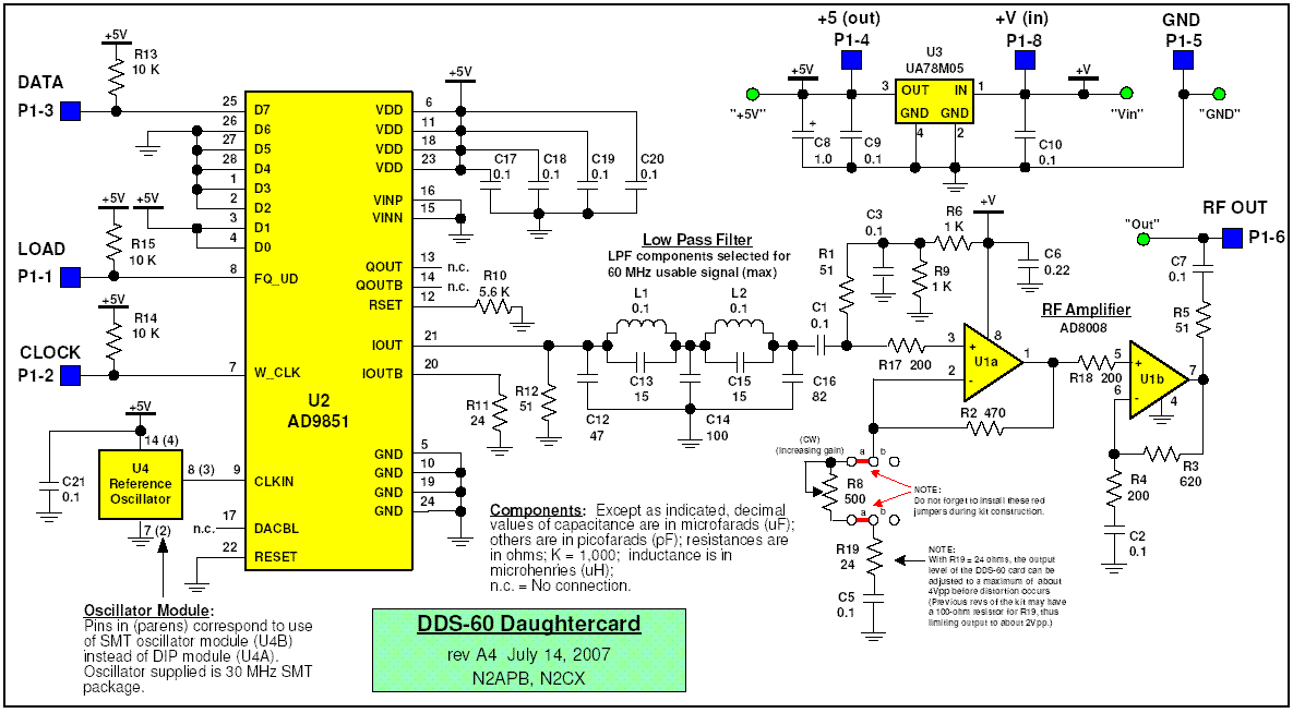
            DDS-60 Kit

            A 1-60 MHz coverage VFO with built-in amplifier and variable output level from 0 to 4V p-p.[/I]


            --------------------------------------------------------------------------
            http://www.qsl.net/n9zia/wireless/pdf/9809037.pdf
            ----------------------------------------------------
            Alberta is under attack... http://rethinkalberta.com/

            Has anyone seen my Bedini Ceiling Fan that pushes the warm air down, and charges batteries as an added bonus? Me neither. 'Bout time I made one!!!!! :P

            Comment


            • #81
              There's a lot more filtration going on there than in domestic water supplies !
              Hmm...not horrendous to build though
              Anyone know of equivalents to the Analog Devices components ?

              News here - the experiments on my bench have courted some interest on YouTube and that's great to see. Some of whom I hope will further the project.
              If so, we'll get this down faster than a 12 bore shotgun aimed at a pigeon

              But, much potential disharmony has been caused by thoughts on the switched off wall adapter. It's switched off....problem ?
              So, in aims of removing some thoughts, I removed the wall adapter !
              Here's a vid, just uploaded, which shows wireless power from just the outside pipe stuck in the Earth

              Zero input voltage wireless - now no wall adapter ! - YouTube

              Comment


              • #82
                Here's something of possibly broader interest than just the PSEC type experiments - a paper coil.
                In fact, here's the story.......
                I was looking at the L3 coils and the dimensions etc, plus knowing how Dr. Stiffler uses pieces of foil to offset capacitances. Then combined that with the knowledge recently acquired about the construction of electrolytic capacitors.
                So, taking a sheet of A4, it was cut to half width, full length. I put a piece of aluminium foil on top of it and rolled it up like a 1960's music festival patron might.
                Thinking of calling it a 'doob coil'

                Here it is, with output lead from a traditional L3 coil type fed into the middle of it. Works if people don't want to wind coils too. Zero voltage input for the pic below and field shown.

                Comment


                • #83
                  Slider and All:
                  After I watched your video, I'm thinking that what we may be seeing is somewhat the same thing.
                  I thought that you and any others might want to check out this new thread started today at Heredical Builders. It's about the effects that we are noticing and some other guys as well, with the Av plugs and leds lighting off of the different ground connections.
                  Exploring the Avramenko Plug - Heretical Builders

                  Comment


                  • #84
                    Thanks. Yes, interesting thread
                    The 15 LED's are the same as the 1 LED, except I found that a small ultrabright green worked better than a white. Then the rest of the spares that I had because of running out of whites made the useful 'power gauge'. The 5 greens will light very readily (as shown in videos) but it's really weird that even so, the others that aren't lighting still conduct. After all, each green is in series with a yellow and a red as I have them wired in lines top to bottom.
                    The Ground feed has to be to the AV plug, then that splits so the LED's run around in series. The other feed, or a hand, then touches 1 of the LED side legs of the AV plug.

                    Comment


                    • #85
                      Slider:
                      I made another AV plug last night, but it lights up much less than the first one, probably the In4001 diodes that I'm using on it. Which diodes have you found to work best on the Av plugs, so far?
                      It's important to find just the right led(s) also, for this purpose, as they are all different in relation to how they work with this kind energy.
                      I've been working on incrementing the brightness on the leds, or power output. It may not be the real thing, but it acts sort of like it.
                      If we could just get the proper starting size, wire lenght and dimensions for L1,L2 and L3 the coils, for this grounds frequency, that would help alot.
                      Any ideas are welcome.
                      Nick

                      Comment


                      • #86
                        Apologies for the picture quality, it's from a webcam because my usual camera is rubbish at close ups.


                        It shows the type i've found to be most effective for size and throughput reasons. I'd like to know the designation, but have no idea as everything here is from salvaged PCB's.
                        Main thing are those two red with yellow band diodes on the 15 LED board, which only appear to drop 50mV. In tests against 1N4148's, they were equivalent on a AV plug. So I don't think they have any betterment of those popular ones...but, they are smaller and that suits when building small circuit boards.
                        To the right, is one of those diodes still on a PCB.
                        Above, are a germanium, a 1N4148 and a 1N4007 for size comparisons.

                        Where I am at, is now trying to incorporate known crystal radio effects. The low drop diodes, ferrite coils and outside Ground have me thinking we're really not very far away at all from such similarities AND i feel that may be why my setup works differently to other peoples !
                        Is that a revelation or what ?!

                        Comment


                        • #87
                          Slider:
                          Thanks, for the info. If you know the diode number that works best that would be better, as the picture is not that clear, and hard to get an idea from.
                          Johnny Davro was mentioning that the L1 can be can be somewhat forgiving, and can be a wide range of inductors, but that the L2 in another thing.
                          It would be nice to just use known inductors instead of having to wind coils ourselves.
                          If find that I can get the same effect when connecting just one wire to my cement battery bank, as I do to the outside ground.
                          So, the idea is to take the small input from the outside ground and use that to resonate some coils, to increment the output?

                          Comment


                          • #88
                            Yeah, that's what i'm stuck on, I don't have the exact part number. It's just a popular small signal diode that's red, with a yellow band at one end

                            For inductors, - Red/Red/Brown (220uH) work in the load sensing circuit I posted in the recent video.
                            For coils - the rolled up 1/2 sheet of A4 with foil 'doob coil' also works well.

                            The basis of my ideas is to use the known effect, of lighting an LED in the hand with an outside Ground. That much appears to be a solid enough known experiment.
                            With just 39uA from my setup, it would also appear evident that we're not exactly in massive power potential territory.
                            However...for wireless energy, we focus on output voltage, frequency and resonance, not amperage. So, that's the forwarding plan.
                            LED's don't need 2.5V and 25mA, that's with old fashioned hammer style electric power. Neither do CFL's, fuoro's and LED lightbulbs need the quantities of electricity stated on their packaging.
                            And, of course nothing, at least in lighting, needs to have a closed circuit and 2 wires to operate.

                            From getting a basic oscillator to produce wireless energy, we can focus on moving up the scales. Those scales need to tip in the favour of increased output, but may decrease the size gains that one day may enable all of a device to fit in the base of a conventional looking bulb (an inverse thought there lol).
                            Along the way, PSEC type effects may be seen...which won't BE the Dr. Stiffler device, but will operate to look like it. Just a different method of creating an end result of visually similar output.
                            What is for certain, is that when I reconnected the switched off wall adapter to the circuit shown in the last video, the output was greatly enhanced compared to previous experiments. The 2 coils that look like L3's mustn't be too far apart in terms of Q. They are physically different in diameter, so I wound the thinner one with a few turns more of the same gauge of wire. It didn't seem to do much, as completely expected, so I took a couple of turns off just to see that nothing changed. Well, that was a guess based thing and yet now see's the pair produce a field 3X the former best that was achieved. Focusing on the smaller and smaller powers can therefore ramp a circuit output when reconnected another way.
                            Or, to put it another way, it seems I tuned it by guesstimated luck and had to, with the reduced power, to get anything at all.
                            Interestingly, nothing is now gained when introducing ferrite to either or both of those 2 coils.

                            An AM radio is really helping. I built a 'thing' last night that needs to be forwarded and based on those crystal set thoughts.
                            A variable capacitor from a radio sits across a ferrite loopstick. One end of the loopstick goes to a 1 wire (of about 40 gauge) that goes around my livingroom horizontally (for 1 wire lighting experiments). The other goes to the Earth Ground.
                            Moving the ferrite piece to just 1 particular spot inside the loopstick introduces a high pitched noise out of the AM radio. Moving the vari cap or touching it, produces raising and lowering tones. The sounds change depending where I put that when the exciter circuit is operating.
                            I'm looking for a tone change, that signifies resonance. Dunno if it even exists.
                            Last edited by Slider2732; 12-04-2011, 12:47 AM.

                            Comment


                            • #89
                              @ Slider and All:
                              I'm still working on this grounds current thing, but, now I see that there is nothing more to this than just Ac leakage, even when using an outside ground only. That is because the hand touching the Av plug is making contact with the Ac leaked current in the house, which goes through ones body, or through the other things available. Same goes for the oscillator.
                              With the above in mind I'm plugging forward. Although this idea can be used to dimly light leds, it's not what I'm interested in, because when there is no Ac power, there won't be any leds lighting, either. So, what's the point...
                              If you just turn off the Ac power to your house for a minute, you'll see all the leds will go out. NO USE BARKING UP THE WRONG TREE...
                              As yourself and others are probably already aware of this, the solution is to back track a bit and use the Docs original three coils methods instead, Illusive as it may be.
                              NickZ

                              Comment


                              • #90
                                Originally posted by NickZ View Post
                                @ Slider and All:
                                I'm still working on this grounds current thing, but, now I see that there is nothing more to this than just Ac leakage, even when using an outside ground only. That is because the hand touching the Av plug is making contact with the Ac leaked current in the house, which goes through ones body, or through the other things available. Same goes for the oscillator.
                                With the above in mind I'm plugging forward. Although this idea can be used to dimly light leds, it's not what I'm interested in, because when there is no Ac power, there won't be any leds lighting, either. So, what's the point...
                                If you just turn off the Ac power to your house for a minute, you'll see all the leds will go out. NO USE BARKING UP THE WRONG TREE...
                                As yourself and others are probably already aware of this, the solution is to back track a bit and use the Docs original three coils methods instead, Illusive as it may be.
                                NickZ

                                @Nick,

                                thats too bad, I was really enjoying entertaining the idea that stiffler really had something that could be expanded upon in that area, but I whole heartedly agree, especially for people who are looking to get off grid, why waste time on dead ends when there are other devices to work on to that end.

                                There are still a couple of areas that I find intriguing however and that is the 1.094 resonance points off center and the harmonics being developed.

                                excellent work btw

                                Comment

                                Working...
                                X