Announcement

Collapse
No announcement yet.

Dr Stiffler SEC Replications?

Collapse
X
 
  • Filter
  • Time
  • Show
Clear All
new posts


  • @stiffler

    Having conversations by proxy always get interesting.

    I cannot speak for Nick but it is my understanding that he was talking about 60 cycle "noise" on the ground wire, not 60 cycle sine wave.


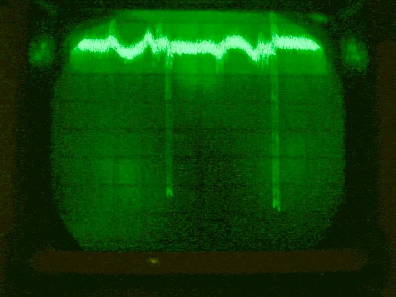
    Noise of course can be "any" frequency see the above picture, that is an "incredibly" noisy ground wire.

    I am sure you realize that when you get a coil very near self resonance it does not take much to keep going and ground wires can carry heavy currents from devices with little ability to take a voltage measurement since it is so low. (the resistance of the wire.)


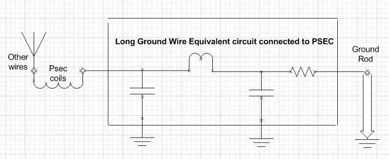
    Finally I am also sure you realize that this is a rough equivalent circuit of a long ground wire and while it makes its way to ground eventually it can often make a better antenna than a ground.

    The test you did was not on point. In other words best I can tell you disproved what was never claimed.

    Its my understanding and feel free to correct me if I am wrong, that the claim was ac (et al) line noise that when the ac mains were shut off the coil stopped working.

    Unfortunately the only way I can imagine making a really conclusive test is to go out into the field as I have stated.

    I have no need to waste my time replicating what appears to me to be obvious.

    On the other hand if one of your replicators want to prove it to themselves and do so I think that would be a great idea. (oh and btw covering the freq)

    Remember, I ALSO said lots of good things about your work so far.

    regards,
    kj

    Comment


    • It is well known that Dr. Stiffler doesn't wish to simply give a circuit and 'all' we have to do is replicate - this is a DIFFERENT project to most.
      More to the point - this type of circuit can't be merely Plug 'n Play.
      He hid the frequency in his latest vid, not to confuse, but to make us find it through experimentation ?!

      I know I was never a radio ham and am intrigued by the simple elegance of the aether energy extraction at highly tuned resonant frequencies. That's why i'm here on this thread.
      Because I don't have a full understanding of what makes what do what, arguably nobody does, i've been posting videos and circuits to hopefully help others who hold similar interests.
      We now know that the 60Hz is a problem for a replication - did we know that before ?
      We now know that circuits can run and light many LED's at least by messy unscientific cobbling of salvaged components - did we know that before ?
      Troublesome Grounds, interfering electrical wiring and more are areas that I would think many had no clue about before.
      A forwarding of thoughts and ideas, to see just what is and isn't needed.

      Dr. Stiffler has just demonstrated that 60Hz is not the way his work works...that, in my view, is brilliant for forwarding this thread !
      If we get 60Hz effects then we're doing it wrong - hoorah! more knowledge!
      It'd be a very short thread if it was simple.
      It'd be a very short thread if all was known before we started.

      Test equipment may be 100% needed (and thanks Nick for the reminder about the SRF in coils, I have no reliable sig gen to know the frequencies though yet).
      If full on test equipment for the definitive PSEC is completely the case, then we get to know that as a fact. Along the way, many of us will have a great amount of fun and learn a heck of a lot

      Comment


      • @kj - interesting info, thanks.
        I started typing before your post came up.
        Heck, I must spend a lot of time thinking lol

        Comment


        • @ Slider and All:
          I think that we are on the same page, as far as now seeing that there no relation between the leaked Ac ground voltages, and what make's Dr. Stiffler's PSEC circuit work. I hope that people did not misunderstand what I had previously said. I just wanted to make this clear.
          As I'm also one of the ones without all of the proper test equipment, I will continue to replicate in whatever way that I can. I will not let that issue stop me, and will do what I can without them.
          Today I buried a 6 foot pipe into the ground outside my house, to continue working with a proper ground. This is the next step in an effort to build a truer PSEC replication. If someone has a reference to the L1, L2, and L3 coil size and starting specs, I would appreciate a link to that information.
          NickZ

          Comment


          • The original thread at OU has been what i've been reading: Selfrunning cold electricity circuit from Dr.Stiffler
            Only at Page 20, but there are circuit diagrams and specs throughout the first few pages. It descends somewhat into *****ing around, but, then the Doc himself makes an appearance and clears much up (bickering and calculations).
            The ferrite loopsticks have proven themselves in my own experiments and are thoroughly recommended to repeat at least the CE4 early similar experiments.
            He seems to then change the L3 to a silvered loose and larger coil and finally to the solder tube type sizing we see lately.

            Comment


            • @k I really doubt anyone will loose any sleep over it. These kinds of things happen in threads. No its not that I disbelieve but like a few others when you work in industry you do not have the luxury of hocus pocus. I have a problem with the procedure. If proper or at least reasonably proper methodology is not used anyone in the industry has immediate red flags flying. Right now there are condition orange flags flying only because as the scope pic shows there can be plenty of NON-60HZ trash on those grounds you are all using. Look at all the triac devices and I have a nice scr welder that will wipe out ever lan network and communication device in a 200 foot building it puts so much noice on the ground.


              @stiffler and all.

              These circuits operate around 10+Megahertz, and that of course is radio frequency. Therefore proper grounding applies, and if the claim is that its coming from the ground then it only makes sense to take it to a remote area (like a swamp) and see if it works.


              Meantime for those interested here are some grounding things that hams have been using over the last 100 years.


              RF Grounding.
              Rf grounding is considerably different than surge grounding. First thing is you are working with RF. Since it is an AC signal it has impedance. The length of the ground runs has much more to do with the fraction of a wavelength at the frequency involved than the DC resistance of the wire. While the DC resistance of a ground wire may be only a fraction of an ohm, the impedance (or the AC resistance at RF frequency) can easily be hundreds or thousands of ohms on the same wire. This can make it pretty difficult to get an effective RF ground. Remember an RF ground wire is just a short antenna! [ see..... I am not jerking anyone around, exactly what I said, hams know these things k. ] We want to make it as LOUSY an antenna as possible! We really don't need it radiating extra RF inside our shack. It is supposed to remove this stuff not cause it. An effective RF ground needs to be less than a quarter wave length at the highest frequency used. As you can see there is no such thing as an effective ground for VHF or UHF. We will concentrate our efforts to 10 meters and above. This means our ground wire from radio to ground must be about 9 feet or less! This is still pretty difficult. All radios, tuners, meters, etc in radio system should be grounded in a star ground configuration. The common point should be at the tuner if one is used, otherwise a ground bus bar can be purchased at an electrical house. All Connections to radios should be with either insulated or bare wire with as few strands as possible. RF likes smooth surfaces best. DO NOT USE braid for RF connections. This is an old wives tale! Your ground run should go directly to the ground where you should have a ground rod for the connection point, (which will be connected to all your other ground rods in the system as discussed above). This run must be less than nine feet to be effective.

              Amateur (Ham) Radio Station Grounding - Get A Good Ground! N8SA
              I think you all get the idea and importance of a good ground.
              Last edited by Kokomoj0; 12-06-2011, 07:53 AM.

              Comment


              • After installing a proper ground with a 6 foot pipe in the ground and less than the 9 feet of wire (antenna) I find it harder to obtain the 60hz interference signal. So, that should mean that I have it right. Now I can focus on obtaining the real deal, and not its impostors Rf frequencies.
                Thank you for that grounds information.
                NickZ

                Comment


                • Great new explanation vid from Dr. Stiffler -

                  PSEC Replicator Help No.1 - YouTube

                  Comment


                  • Originally posted by Slider2732 View Post
                    Great new explanation vid from Dr. Stiffler -

                    PSEC Replicator Help No.1 - YouTube
                    I've managed to replicate his 3 coil set up but with less power than Dr. Stiffler is getting from them and his latest, in that video using the FG, sec18x and a little playing around. Haven't managed the 48 LED's yet but I'll get there...

                    Fun project !

                    Comment


                    • @Dragon
                      That's really good news. If you can give details about your set up that others can use to do this, we are grateful someone finally got one going.
                      Last edited by mikrovolt; 12-09-2011, 04:35 PM.

                      Comment


                      • Originally posted by mikrovolt View Post
                        @Dragon
                        That's really good news. If you can give details about your set up that others can use to do this, we are grateful someone finally got one going.
                        It is as Dr. Stiffler shows in his video. I have both the new and old Sec18x boards and the one that seems to work the best is the older boards with the sewing bobbin coil although the other one works it's just not as bright on the LED output. I played with it for many hours with varying degrees of success and spacing of all the components is critical, a few mm makes a big difference as to if it works or not. I'm just playing with it and trying to get a better understanding of what he's doing, I'm not sure of any other way to explain it as I don't fully understand it's workings. I still haven't conquered the "self running" mode of the Psec but I keep trying.

                        Comment


                        • Dragon and All:
                          Thank you for sharing your findings. It really is good to see someone making some head way with this. I liked the simplicity of your set up in the video, and I wish that I also had the 18x boards to work with. I will however continue working against All Odds to find the way to make the same effect work for me. But it is one heck of a circuit to replicate, and racks my brain even just trying to understand it correctly. There is no other way of learning about this, other than hands on. Reading or talking about it will not be enough.
                          I seamed to have opened a can of worms, with the ground connection misunderstandings, and hope that we are now back on track without further ado. But, it was a very important point, or obstacle for those of us working on this, to isolated all other influences from affecting this Passive SEC Circuit.

                          Dr. Stiffler, you are a magician... I thank you for having the patients to even deal with us. I assure you that we are listening... as crawling is not that easy, either, and takes some time, with lots of hard knocks. If it were not for you guiding our way, crawling may be all we'd be doing.

                          NickZ

                          Comment


                          • This guy, ariochdm just put out this video, and I sort of got it a bit confused with the Dragon's video as I watched them both together. Anyway, it's this video that I was noticing about the simplicity of his test:
                            SEC Experimentation with aluminum blocks Part 3 - YouTube

                            Dragon's video was also nice to see.

                            Comment


                            • I'm delighted to see these progress reports. Yep, we did get somewhat stuck in the Grounds, but indeed it is all very important to understand.
                              The way I picture this (and I hope dragon agrees) is of many different radio waves that intersect, but that we can't quite see. To mentally picture the waves of a scope, in front of a setup. Only when components cross at exacting points, will any effect be seen. A noisy Ground could, therefore, stop any and all effects from being seen !
                              With such a way of thinking, ariochdm's video is easier to understand, in that the exact distance between the metal blocks can be where he crosses that scope looking wave and the LED comes on. His mass of cables would form a capacitance to shuffle the received signal to that crosshair point. If he moves them or uncurls them or touches a block, he moves the receiving block out of the crosshair.

                              I've gone sideways, but am just reporting a finding related to the experiments, using loopsticks. I'm not much further into the huge OU thread because of wishing to explore them a bit before moving along. So, loopsticks are being looked at.
                              Ya know how people sometimes detect oscillators running with an AM radio ?, well, it was Dr. Stiffler's last video with the aluminium block to assist RF that got me going. That energy is thrown outward, like the emissions of SSTC's ! We don't want that, we want to use all that we can and feed it back into the circuit.
                              Using a loopstick on a garden solar light based blocking oscillator as the coil, another loopstick was fitted with an AV plug on one pigtail. The other pigtail was left open ended.
                              When placed at an exact point at the very side of the running loopstick, recovery voltage from a 1.2V AAA was almost as much as the source voltage, but milliamps were nearly zero. However, the AM radio range of pickup of the oscillator decreased to about 1/5th of the range.
                              I'm running a test at the moment and the last two hours have seen the source battery lose 0.008V, the charge battery gain 0.004V and the red ultrabright LED has been nicely lit all the while. The recovering loopstick feeds into the source battery.
                              Anyway - not to do with the PSEC, but thought it may help with understanding about emissions and reusing those otherwise wasted energies. Capturing them and feeding them back, as Dr. Stiffler did with the 1meg resistor and block
                              As an addendum - the solar lights originally used a horrendous 150mA as stock setup. By using the twin loopsticks and a 103 cap plus 2K variable pot in series with the main loopstick, the current draw fell to 0.87mA before this idea of the recovering loopstick.

                              Comment


                              • It all circulates, at least it tries and we can improve the circular pathways.
                                Crystal sets work outside AM the possibilities are immense, unfortunately it is technically not on the same page with mainstream current SEC replications. There are many replications and some are lacking details.
                                Since those details can make a difference to a serious replication it is important to find working details.

                                Just as crystal sets can be viewed outside AM radio also a receiving antennas can take on many shapes and there can be many units resonating, sending and receiving all sitting on the same table. Now the ground is where the electrons are headed.

                                The AC potential is higher when the ground is separate from the antenna.
                                The mechanism allows a feed point at the base of the resonating antenna while keeping the ground separate, this ground point is a sink hole drawing electrons it can be an air gap and in another part of this open circuit it can be a diode.

                                I think it is part of the process in understanding SEC to revisit AM
                                and sort thru what is the same and what is different. Adding knowledge
                                to what you know, another way is to contrast such as; one thing that is different about AM is that it narrows the received spectrum whereas SEC encourages the expression of harmonics of one of the frequencies used to excite.

                                Comment

                                Working...
                                X