Announcement

Collapse
No announcement yet.

Bi-toroid Transformer of Thane C. Heins

Collapse
X
 
  • Filter
  • Time
  • Show
Clear All
new posts

  • Stan Meyers

    Originally posted by Dog-One View Post
    So guys, I have been watching this video over and over, along with the link below:

    AT&T Archives: Similiarities of Wave Behavior (Bonus Edition) - YouTube

    Focus on figure 6c.
    Resonances, waves and fields: 3.20 Derivation of wave properties for transmission lines

    Maybe this is simply another way to explain Thane Heins' and Bill Alek's theory of operation. The way I look at it, is somehow we are creating a standing wave in the primary and because of the impedence mismatch between the primary and secondary, we are getting real power out the secondary, using only reactive power in the primary. Sure sounds a lot like the SERPS doesn't it? And maybe even Stan Meyer's VIC.

    If you pay very close attention to John Shive's presentation, he walks you through SWR and impedance matching, which is where I think the magic is with this and many other devices. And if you study Figure 6c of the other link, you will see how it is possible for there to be real energy emitted, with only reactive power used to produce the waves. I think this is what is happening with the SFT. You have in effect a transmission line coming into the SFT and two transmission lines leaving it. The transmission line entering the SFT on the primary side sets up a standing wave (i.e. reactive power, amps/volts 90 degrees out of phase). Then these waves exiting the SFT on the two secondary sides are impedance matched to provide real power to the load. The frequency, the ratio in size between the cores and the turns ratio all work together to extract real power from reactive power. And I'll propose this is the same theme for many OU-like devices.

    Has anyone fully digested Eric Dollard's Four Quadrant Representation of Electricity, enough to comment?

    Here's another quote regarding the SFT that needs to sink in:

    Resonances, waves and fields: 3.21 Reflection and absorption coefficients for transmission lines with loads

    Hey Dog_one

    Great stuff to think on.

    I like these old vids. Remember RUSS? The guy taking the pictures at Bills place? Here he is talking about SM SELF SUSTAINING CYCLONIC TRANSFORMER. The core is a gas and the particles inside of the tubular toroidal core are accelerated much like an atom smasher.

    The Key To Stanly Myers Water Car Gas Core Transformer Self Staining Device - YouTube

    HHO needs a lot of power for the process and ole Stan did not get all of the power off his dune buggy alternator he got it by building a wave machine.


    Its not a bi toroid, it is self sustaining and the key to any work.

    I now have 4 C-Cores and the wire.

    Mike

    Comment


    • Tape

      Originally posted by Hrothgar View Post
      Metglas "meg" cores can be bought on eBay but if you scour it thoroughly you can find the tape that the cores are made from. So a kHz custom core is attainable.

      I have searched high and low for tape without buying a tractor trailer load of 100 tonnes. Where can this tape be found?

      I have asked around this thread for help with no reply til I saw this post. Where?

      Mike

      Comment


      • Stan Meyer EPG

        Originally posted by BroMikey View Post
        I like these old vids. Remember RUSS? The guy taking the pictures at Bills place? Here he is talking about SM SELF SUSTAINING CYCLONIC TRANSFORMER. The core is a gas and the particles inside of the tubular toroidal core are accelerated much like an atom smasher.

        Its not a bi toroid, it is self sustaining and the key to any work.
        If Ken would mix up some of his famous Ferrofluid, place into a large vile and cap dump it hard enough, we could send that stuff to Russ to test in his EPG replica. BTW, I held Russ' EPG in my hands; it's quite a piece of workmanship. And from what Dr. Greer states, the EPG was key to Stan getting his dune buggy running on water, because the EPG is actually the powerplant.

        Comment


        • Metglass tape.

          Here are some for sale:

          metglass tape | eBay
          http://www.youtube.com/watch?v=jeYscnFpEyA

          Comment


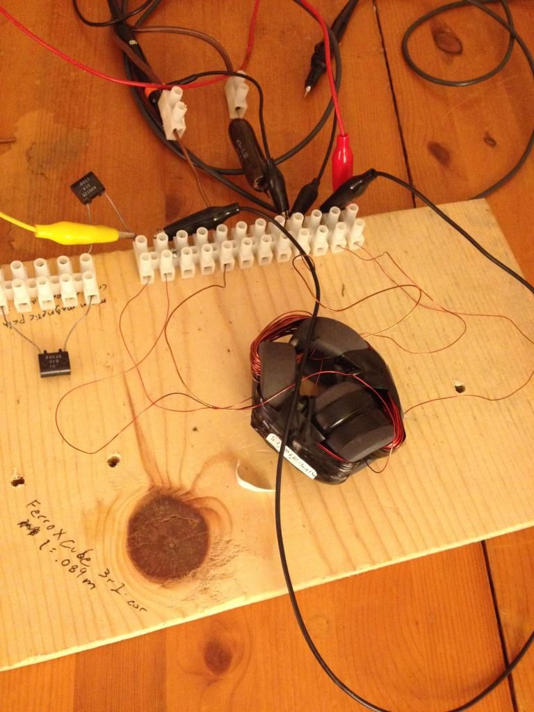
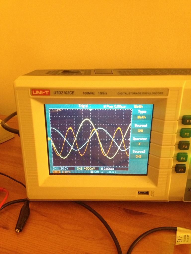
          • I encourage everybody to follow the Thane Heins concept. I've began to see interesting results. I've only been seeing these for two days and still trying to hunt out any flukes, but I'm starting to consistently be able to produce a negative power factor while powering a small lamp. The phase angle has been displaced well above 90 degrees. I measured at a dead short a phase angle of 106 degrees and with the lamp, 105 degrees, according to my scope which I plan on double and triple checking elsewhere. I'll post some pics when I can figure out why my computer won't let me access photobucket.

            Cores - FerroXCube - 3r1
            Secondaries - 2x 100t 26AWG
            Primary - 38t 23AWG

            Dave

            Comment


            • This is my transformer.

              Comment


              • Apparently it will be one pic at a time..

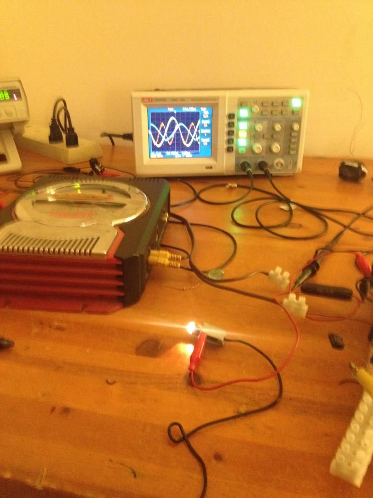
                This shows my lamp dissipating energy and the scope in the background.

                Comment


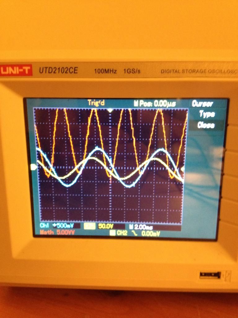
                • This is a close up of my wave. The circuit has capacitance in the secondaries so the current is leading the voltage. The power wave can be distinguished as redish and 2x the fundamental frequency. NOTE the area under the power wave which is directly representative of energy exchange.
                  Last edited by Web000x; 09-27-2014, 06:17 AM.

                  Comment


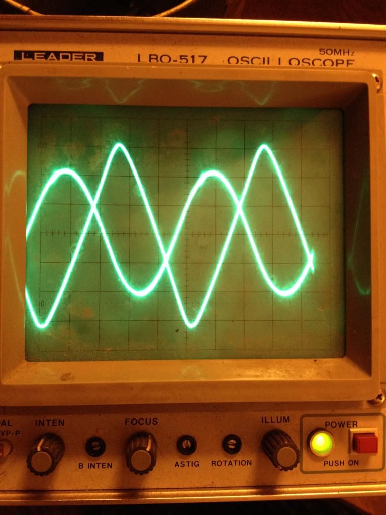
                  • This is a scope shot using an analog scope. The amplitudes are different than from the previous digital scope shot so you can observe the voltage as having a spike on the crests. Still you see a a 90+ degrees cosine angle while there was light emitting from my lamp.
                    Last edited by Web000x; 09-27-2014, 06:34 AM.

                    Comment


                    • For good measure, here is a standard transformer being displayed under load on the same scope with the same test probes, obviously voltage leading current in the pic.
                      Last edited by Web000x; 09-27-2014, 06:28 AM.

                      Comment


                      • Exciting Results

                        Originally posted by Web000x View Post

                        For good measure, here is a standard transformer being displayed under load on the same scope with the same test probes, obviously voltage leading current in the pic.
                        That is so good. You are in lead position here.

                        Way ahead of me because I can't work my 1 mhz 2 channel scope yet.

                        Keep up the good experiments showing mostly never beofre seen results and don't listen to people who have no working setup either.

                        If people think it is totally explainable, how can the explain away something they can't produce? The others just don't want to prove this stuff right.

                        You have done it. Top Dog so far in my book.

                        Mike

                        Comment


                        • Many Thanks

                          Originally posted by Michelinho View Post
                          Here are some for sale:

                          metglass tape | eBay
                          Thank You. I will need to make a big one the second time around and this is a way to make shapes like Thane has. I wanted to see if the square shape like Thane uses is better than C-Cores.

                          Mike

                          Comment


                          • Using a resonant air core transformer with a secondary tank circuit I can get
                            some odd phase differences while driving a ferrite transformer powering a wire
                            wound resistor. Different loads and adjustments produce all kinds of odd results.
                            But no matter what the odd wave forms and stuff show the output is always less than the input for me.

                            Can anyone show actual more energy out than we put in ?

                            These wave forms are 2) from the resonant tank driving the primary of the
                            ferrite transformer and 1) is from the wire wound inductive resistor
                            load. Blue traces are the voltage sensed across a 0.1 Ohm resistor to determine
                            the current.
                            ..
                            Attached Files
                            Last edited by Farmhand; 09-27-2014, 01:08 PM.

                            Comment


                            • Nice!

                              Originally posted by Web000x View Post
                              This is a scope shot using an analog scope. The amplitudes are different than from the previous digital scope shot so you can observe the voltage as having a spike on the crests. Still you see a a 90+ degrees cosine angle while there was light emitting from my lamp.
                              Looking good.

                              I think the trick with these devices is getting the impedance matched properly, that's where we will see some power gains, maybe even enough to strive for a looper.

                              Something I have thought of that you can only do with the SFT and not the BiTT is adding more secondary turns either around the primary cores or the secondary core. I have no idea what you may see, but it would be a great test if you are willing to try it. If for no other reason, it may allow us some flexibility in the types of cores we choose and still get optimal performance.

                              Probably two things we should post with experiments like this are the power usage of the amplifier (idle and running) and the frequency of the signal generator.

                              Great work Web000x!

                              I should be recieving my AlphaCores next week and I'm really looking forward to getting some results, hopefully as good as yours.
                              Last edited by Dog-One; 09-27-2014, 02:57 PM. Reason: Additions

                              Comment


                              • Originally posted by Farmhand View Post

                                Can anyone show actual more energy out than we put in ?
                                Now that would be the whole point to this endeavor, wouldn't it? Right now, I can confidently say that this circuit is extremely inefficient due to my power supply being an audio amplifier. The amp doesn't seem to care much about reactive power being returned and continues to consume power from the battery. However, if this were a mechanical alternator/generator, I might see reduced drag and increased rpms on the rotor. The point of me posting these pictures was not to claim OU, but rather show people that I am getting a novel waveform that falls in line with what AuroraTek and Thane Heins showed and to encourage more experimentation. I worked with a lot of magamps back around the time I was involved with Eric Dollard, but never did I see any negative power factors, until now.

                                I don't understand how you came to the conclusion that your circuit was not novel when you clearly saw a cosine angle of 111 degrees. What made you think there was nothing there worth investigating further?

                                Dave

                                Comment

                                Working...
                                X