Announcement

Collapse
No announcement yet.

Bi-toroid Transformer of Thane C. Heins

Collapse
X
 
  • Filter
  • Time
  • Show
Clear All
new posts

  • Originally posted by Web000x View Post
    I plan on winding this next one with as many secondary windings as possible. Not sure how many I can get, but Bill had a small primary with BIG secondaries. I'm seeing that the dielectric side of the secondaries is the way to go. I also have that unbalanced secondaries core to modify since I'm not impressed with it. Maybe I'll strip off the secondaries and try a 1:1.

    Are you suggesting I use one conductor to wind a turns ratio test? Kinda confused...
    Turns ratio of this SFT is a little confusing. You have the turn count on the primary (true primary) input side.

    Then you have turns for the two secondaries, both the count around the primary core and the larger Back EMF core. Everything so far has this count 1 to 1. I'm suggesting that these secondaries also have ANOTHER ratio. That being the count of turns coming off the two primary cores and the count around the larger Back EMF core (calling this a secondary core is probably where the confusion is). From now on I'll call the single large core that couples the two secondary windings together the Back EMF core. So you have in the SFT:

    One primary winding that loops around both primary cores. There should be no ratio here; always 1 to 1.

    Two primary cores.

    One Back EMF core.

    Two secondary windings.

    I'm suggesting Bill showed us a setup where the secondary windings are 1 to 1 around each primary and Back EMF core. We don't know if this is optimal for the secondary windings. It very well could be that having more total turns on the Back EMF core than on the primary core for each secondary winding is better. Or maybe having more total turns on the primary core than the Back EMF core gives better results. Either way, each secondary winding should be done exactly the same. The split flux should be symmetrical. Bill thinks this symmetrical split flux design creates Cooper electron pairs and he could be right, so we need each secondary winding to be built identical.

    So I'm sure I have you really confused now right Dave? hehe

    Lets review all these turn counts with just example numbers:

    Primary turn count for primary winding: 50

    Secondary turn count for one side: 75 around primary core, 100 around Back EMF core.
    Other secondary is identical to first.

    So lets look at the ratios. We have a 50 : 75 (2/3) step-up. We also have a 75 : 100 (3/4) Back EMF recovery ratio. This ratio is what we need to explore.

    If it's still not clear, just hang tight until I get my new cores and I'll try to do a video showing what I'm talking about.

    Comment


    • Tuning

      Okay so Bill has a transoformer he thinks produces Cooper electron pairs


      Cooper pair - Wikipedia, the free encyclopedia


      No problem. But what I am wondering about is why you are talking about there being 4 windings? It is my understanding that Bill is showing 3 separate winding as designated by their inductance values.

      Unless you are looking for other setup possibilities? Are you guys adding a fourth coil? Maybe to self loop?

      This is only a guess. We all saw Lasersaber leading the way along with Adula, Mr Clean adding coils of all kinds.

      Is there something about the Thane and Bill setups that might use more coils?


      The above sounded like two primaries and two secondaries. Did Bill tell you by email what he thought about the electrons?

      It has been my understanding that the transformer consists of a single primary that becomes a high reluctance pathway by comparison the the double secondaries that oscillate between one another.

      This never ending reflected wave oscillation has the ability to build up or magnify the energy that was initially pass to it by the primary (Single Winding)

      When the primary electrically pulsates in the form of AC current and AC voltage THAT energy is passed to both secondaries (One on the right and one on the left) at the same time.

      Also at the same time each secondary receives energy to charge wire coils mass. Both are now charged and ready for collapse.

      Both collapse and both give back a spike in the form of back EMF Or other terms CEMF .

      When the energy leaves both coils at the same time (Both Secondaries) the reflected kick back crosses paths over top of each other and cause possibly a stress as they pass to REFILL the empty coils simultaneously.

      So I think this stress causes a vortex as the reflected energy quickly passes one another to REFIL themselves.. Finding the right voltage and frequency along with tuning capacitors should be all that is needed to optimize output.

      In Bills video he had everything mounted to a PCB board. Maybe some tuning caps are on this board.

      If a fourth winding is used for other experiments let me know how when you can.

      Mike


      Originally posted by Dog-One View Post
      Turns ratio of this SFT is a little confusing. You have the turn count on the primary (true primary) input side.

      Then you have turns for the two secondaries, both the count around the primary core and the larger Back EMF core. Everything so far has this count 1 to 1. I'm suggesting that these secondaries also have ANOTHER ratio. That being the count of turns coming off the two primary cores and the count around the larger Back EMF core (calling this a secondary core is probably where the confusion is). From now on I'll call the single large core that couples the two secondary windings together the Back EMF core. So you have in the SFT:

      One primary winding that loops around both primary cores. There should be no ratio here; always 1 to 1.

      Two primary cores.

      One Back EMF core.

      Two secondary windings.

      I'm suggesting Bill showed us a setup where the secondary windings are 1 to 1 around each primary and Back EMF core. We don't know if this is optimal for the secondary windings. It very well could be that having more total turns on the Back EMF core than on the primary core for each secondary winding is better. Or maybe having more total turns on the primary core than the Back EMF core gives better results. Either way, each secondary winding should be done exactly the same. The split flux should be symmetrical. Bill thinks this symmetrical split flux design creates Cooper electron pairs and he could be right, so we need each secondary winding to be built identical.

      So I'm sure I have you really confused now right Dave? hehe

      Lets review all these turn counts with just example numbers:

      Primary turn count for primary winding: 50

      Secondary turn count for one side: 75 around primary core, 100 around Back EMF core.
      Other secondary is identical to first.

      So lets look at the ratios. We have a 50 : 75 (2/3) step-up. We also have a 75 : 100 (3/4) Back EMF recovery ratio. This ratio is what we need to explore.

      If it's still not clear, just hang tight until I get my new cores and I'll try to do a video showing what I'm talking about.

      Comment


      • Originally posted by BroMikey View Post
        No problem. But what I am wondering about is why you are talking about there being 4 windings? It is my understanding that Bill is showing 3 separate winding as designated by their inductance values.

        Unless you are looking for other setup possibilities? Are you guys adding a fourth coil? Maybe to self loop?
        Nope, no fourth coil. Only three.

        Video explanation: http://vimeo.com/107858044
        Last edited by Dog-One; 10-02-2014, 08:32 PM.

        Comment


        • Alternate Fux Paths

          Originally posted by Dog-One View Post
          Nope, no fourth coil. Only three.

          Video explanation: SFT Winding Variations on Vimeo

          Hey Dog-One

          Great vid and now I see what you mean. The bi-toroid works off a balanced twin secondary or altered secondary ratio's work of harmonics of the main frequency.

          Try it and see.

          Does everyone understand my statement? The more windings added to the primary bring about a more direct path back to the primary from the secondary. What we want is the create an impeded flux path back to the primary while the pathways between the secondaries be 100 times less resistance.

          Increasing the number of turns effects impedance so the flux path is more directly connect to the secondaries, this will produce a greater draw on the primary.

          However the shorter turns just on the primary windings do not increase direct coupling but might allow a higher input voltage to the primary.


          Other factors are getting each set of coils identical. This is because we want oscillation equal and opposite in the secondaries at the split primary so tuning might be needed for the new coil arrangement.

          Beyond that I don't know what else to say about the addition of the shorter windings with a variety of possible turn pattern vs ratio.

          Yet when you think about it those extra coils as short and isolated as they may seem, store energy and induce a higher voltage that is accompanied by a greater density magnetic field.


          Let's say normally the primary is 40 turns and you decide to try a shorter coil every other wind so the turns on the large core now drop to 20, instead of 40, so this would maybe lower the current and maybe the stored energy in the other portion of the coils might increase voltage.

          Its worth a shot if we can get the thing working in normal operation, who knows THAT might give more control in other ways.

          Thanks for the video that make everything much clearer.

          Mike
          Last edited by BroMikey; 10-03-2014, 02:06 AM.

          Comment


          • More on turns ratio...

            Originally posted by BroMikey View Post
            Thanks for the video that make everything much clearer.
            I see now what needs to be done to get this to work as optimally as possible.

            First, we need to decide the step-up voltage ratio we want to have. This is easy and we can do it without even having the Back EMF core. We simply wind the primary, connect it to our amp and then add a secondary winding, adding turns while watching a volt meter until we have the target voltage we are after. While doing this, we need to adjust frequency to get the value that provides the best coupling we can find. This will give us the turns ratio for both sides of the primary and the operating frequency.

            Second, we strip off the secondary we just wound and keep track of the number of turns we had, we will need this value later.

            Third, we wind the Back EMF core only with two windings using the number of turns we just found in step two. 1 : 1 ratio. Connect one side to the amp and look at the voltage coming out the other side. Here we leave the frequency fixed that we found in step one. Then we add or remove turns equally from each side of these two windings to find the max voltage, best coupling. Now we should know the correct number of turns for the Back EMF core.

            Fourth, we strip off the windings from the Back EMF core and begin to wind the complete SFT using the values we found previously. To do this we look at the two turn values we found in step two and step three. Whichever value is lesser, that will be the count of turns that go around both the Back EMF core and the primary core. Now we take the difference of the two values; this will be the number of additional turns that go around either the primary core or the Back EMF core. If the value in step three is larger than the value we found in step two, the remaining turns will go on the Back EMF core. Otherwise we put the remaining turns on the primary core.

            Fifth, duplicate the other secondary exactly the same as you did in step 4.

            Doing this should result in having an SFT that has optimal coupling throughout all the cores, give or take. It's possible that additional tuning will be necessary, but I would expect this technique to get you pretty close. I'll be doing this technique myself when my cores arrive. Which reminds me, I need to check and see if I have a tracking number...
            Last edited by Dog-One; 10-03-2014, 05:21 AM. Reason: Tweaks

            Comment


            • 101 Winding Instructions

              Hey Dog-one

              Good Idea. I'll never forget how I have ripped the windings out of the MOT and kept watching the volt meter as I added turns. It turns out most MOT have a ratio that when I put 1 turn I get 1 volt more so if I am making a 24vdc charger I use 36 turns or 36vdc no load.

              Watching a meter is the only way sometimes.

              The way I am going to do this is fill my core material so it is a tight transformer and whatever comes out will go to capacitors to charge batteries.

              This is why i am thinking along the lines of a car audio amplifier so I can drive it with DC 12 volt battery. Then if my voltage is 50vdc (Lets just say it is) on the output I can charge two 12vdc batteries dumping them with 50 volts.

              Or when the primary side goes down I can use a battery changer to swap out the half dead one for a full one.

              I want to close the loop one way or another (Have not decided) so I have a self contained battery charger like the ELECTRIC BIKE companies are doing.

              It's not like we are breaking new ground here. I just want something practical and those guys get all of the credit.

              Mike PS does anyone know why it does or doesn't matter if CCW and CW makes any difference on these Bitt's???? Talk to me somebody.


              Originally posted by Dog-One View Post
              I see now what needs to be done to get this to work as optimally as possible.

              First, we need to decide the step-up voltage ratio we want to have. This is easy and we can do it without even having the Back EMF core. We simply wind the primary, connect it to our amp and then add a secondary winding, adding turns while watching a volt meter until we have the target voltage we are after. While doing this, we need to adjust frequency to get the value that provides the best coupling we can find. This will give us the turns ratio for both sides of the primary and the operating frequency.

              Second, we strip off the secondary we just wound and keep track of the number of turns we had, we will need this value later.

              Third, we wind the Back EMF core only with two windings using the number of turns we just found in step two. 1 : 1 ratio. Connect one side to the amp and look at the voltage coming out the other side. Here we leave the frequency fixed that we found in step one. Then we add or remove turns equally from each side of these two windings to find the max voltage, best coupling. Now we should know the correct number of turns for the Back EMF core.

              Fourth, we strip off the windings from the Back EMF core and begin to wind the complete SFT using the values we found previously. To do this we look at the two turn values we found in step two and step three. Whichever value is lesser, that will be the count of turns that go around both the Back EMF core and the primary core. Now we take the difference of the two values; this will be the number of additional turns that go around either the primary core or the Back EMF core. If the value in step three is larger than the value we found in step two, the remaining turns will go on the Back EMF core. Otherwise we put the remaining turns on the primary core.

              Fifth, duplicate the other secondary exactly the same as you did in step 4.

              Doing this should result in having an SFT that has optimal coupling throughout all the cores, give or take. It's possible that additional tuning will be necessary, but I would expect this technique to get you pretty close. I'll be doing this technique myself when my cores arrive. Which reminds me, I need to check and see if I have a tracking number...

              Comment


              • Uh-oh, a 3-month delay on all products, no explanation. Let's hope this doesn't turn into another Keshe-like fiasco.

                Comment


                • Originally posted by sprocket View Post
                  Uh-oh, a 3-month delay on all products, no explanation. Let's hope this doesn't turn into another Keshe-like fiasco.
                  That's not very good news, but not the end of the world.

                  What would be really bad news is if the suppliers of these magnetic cores release a similar announcement. That would pretty much end things around here.

                  Comment


                  • EV Bike Builders

                    Originally posted by sprocket View Post
                    Uh-oh, a 3-month delay on all products, no explanation. Let's hope this doesn't turn into another Keshe-like fiasco.
                    Those EV bike builders are buying up all of those pretty C-Cores for the newest crazzz since the hula-hoop!!! A Bike that self charges!!

                    There must be other suppliers right?

                    Mike

                    Comment


                    • Originally posted by BroMikey View Post
                      Those EV bike builders are buying up all of those pretty C-Cores for the newest crazzz since the hula-hoop!!! A Bike that self charges!!

                      There must be other suppliers right?

                      Mike
                      Who know, Bill could be soldering furiously as we speak, trying to get that Haiti order fulfilled before pandering to us minions! Can't hurt to think positively.

                      Comment


                      • If you want to build a transformer type device go for the gusto do something different. I would advise a magnetic shunt be incorporated.

                        Center coil (primary) resonant tank circuit
                        Outer coils series resonance
                        Half of the Answer is knowing the right Question

                        Comment


                        • Sphere

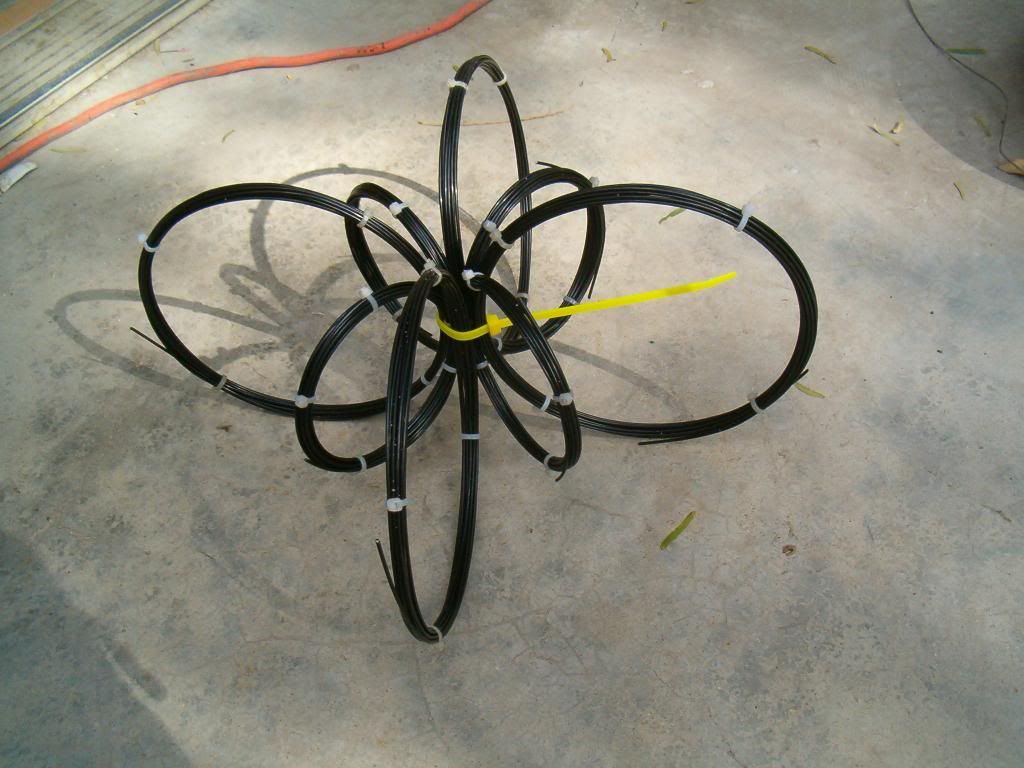
                          Hi Dave45, That pic is very similar to my spherical magnetic rotor I made.
                          The magnetic fields off of mine were equal strength at any location of the arc ,I wonder what the fields would be like if you put power into that .
                          Thanks for the idea I use magnets , but never thought of using electro-magnets.
                          artv

                          P.S. Is a coil considered an electro-magnet if it doesn't have a core?

                          Comment


                          • Large coil windings 60HZ 169 volts AC Input Side

                            Straight AC coming off the wall Thanes Video.

                            Look at the size of those windings. 169 volts AC on the input side.


                            https://www.youtube.com/watch?v=x7JDElxCyX4


                            No Frequency just AC but his cores are high frequency response type.


                            Mike

                            Comment


                            • Originally posted by BroMikey View Post
                              Straight AC coming off the wall Thanes Video.

                              Look at the size of those windings. 169 volts AC on the input side.

                              No Frequency just AC but his cores are high frequency response type.
                              Understand when you wrap a primary core, the number of turns is directly related to this formula:

                              Turns = VoltsRMS / 4.44 / meters^2 / Hertz / Tesla

                              Tesla (working flux density of the core material) being in the neighborhood of 1.0 to 1.7.


                              I think I mentioned this, I requested two quotes from suppliers that can manufacture custom cores and they were both asking about 900 dollars to build me such a core. If I truly thought I could get 1000 watts out of such a transformer, I would have made the investment already. Notice Thane's load, a dimly lit 2 watt bulb. Pretty hard to justify.

                              I do think Thane's concept is workable, I just don't know that we can acquire the materials to make something viable without a serious financial investment. Which is why the Bill Alek derivative makes more sense--we can get commercially available toroids and C-Cores for considerably less money. And if we run at higher frequencies there will be electronics involved, but we all see how the progression of linear power supplies morphed into switching power supplies, so we can follow the same path. Maybe in the end we can have 1000 watt, 10% PF devices that are relatively small and inexpensive. The goal is right there just within reach if we work for it.

                              Comment


                              • Demo

                                Agreed Dog-One

                                Thanks for the transformer winding calculation I need to brush up on figuring instead of just using what I have.

                                The demo is Thanes come on to propose to other companies who may research and develop this stuff. We don't have a $100,000. However $200 might get enough tape to make any SHAPE but there is still the matter of nano-crystalline compatibility based on calculation as you have pointed out.

                                What the video does do is gets the average Joe experimenter off of the chalk board and into the game room where coils are wound. While $900 is a bit steep for our pocket book especially if it lands in the pile as a failed project afterwards, we might rerun some of those figures til we turn the tables around like Bill did in using standard low cost cores.

                                Still in all without circuits we can explore whether or not the principle works and while the input is a few watts for all of that core material expense the output is twice.

                                This beats the one watt challenge like the dead horse that it is.

                                Then if we are not getting enough to be practical later each one us could take the same core material we got our hands on for the price we can afford and feed it with AC ofa higher frequency. So we are not out the money either way we go.

                                When I went to Micro-metals one time to get a Bob Boyce core or two they only had one that works in that frequency band. So there isnt that many out there.

                                But what you are talking about to true, raising the frequency on the same core with the right windings could give a 100X price to output ratio like the switch mode industry operates.

                                Still the demo is a delight because I can go into the lab at anytime and prove this out for myself with wall current.

                                The formula is good to find Dog-One with so many around it is sometimes hard to decide witch approach is enough for our design.

                                If you are this good with the math I would say you are a great asset to our transformer builds. Thane said in the video he would always get at least twice as much power out for the same input of a conventional transformer using the Bitt even at 60hz.

                                This is very encouraging.

                                I have a pile of flyback transformer cores I am working on to get them out of televisions. People give them to me (The old ones) so resently I have learned not to break them by cutting of each side of the cores putting a bandsaw blade along side or flush with the cores making a cut on each side.

                                The core just fall out.

                                This material is high frequency material so I think it will work but like I said I do things to save money if I can and I am not so sure it will be the most optimum.

                                Getting the Frequency up and thus the power levels per unit cost whatever the output voltage is should be a great first step with enough to loop the thing even with many losses.

                                Mike
                                Last edited by BroMikey; 10-04-2014, 05:18 AM.

                                Comment

                                Working...
                                X