Announcement

Collapse
No announcement yet.

Bi-toroid Transformer of Thane C. Heins

Collapse
X
 
  • Filter
  • Time
  • Show
Clear All
new posts

  • Originally posted by BroMikey View Post
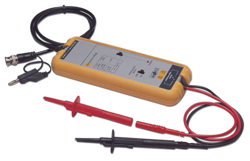
    Do you measure using a differential probe without issue?
    Currently I'm not using diff probes--they're a must for something like a Stan Meyer VIC. Most of the ones I've seen have a battery inside them for power, at least my BK Precision ones do.


    Without diff probes you have to have common for both probes on the negative side of the resistor and make sure you have no ground connected from your scope to house power. I'm really not too fond of this because one takes a chance on getting zapped or smoking the equipment. If you're careful and really think through how you have everything connected, you can get away with it. Just make sure you don't have a ground path from your scope to your amp and that you connect the common on your probes to the exact same location.


    And Dave, a good current probe would be nice, but they're pricey too, usually more so than a decent differential probe. I tend to think if we use a small ohm carbon resistor, we should be in good shape. I'm using a 0.12 Ohm that seems good so far, at least it has been for low frequency.
    Last edited by Dog-One; 10-16-2014, 12:34 AM.

    Comment


    • Carbon

      Hey Dave how about this 1ohm 5watt metal oxide film stuff?


      Originally posted by Web000x View Post
      Mike, I'm unsure of how you are going to use a differential probe to get an accurate current reading. I think we'd probably be more interested in current probes? Maybe I missed something..

      Comment


      • [QUOTE=Dog-One;265940can get away with it. Just make sure you don't have a ground path from your scope to your amp and that you connect the common on your probes to the exact same location.


        [/QUOTE]


        I was thinking the motor to a motor trick might keep me from the grounding problem. I am seeking isolation is any form easy to get. Do you think it will work?

        Mike

        Comment


        • Dummy Load

          Here is an audio amp dummy load resistor. Look at the criscross windings.

          Says its non inductive. 1 ohm and 100watts $19


          Mike

          Comment


          • Originally posted by BroMikey View Post
            Ask Dog-One he thinks this can eliminate some ground and other measuring troubles. I don't think I have a probe like that anyway. I have a 1 ghz probe and some slower that come standard with the HP54100D.


            Talk to me Dave. I need to hear more on the possibilities with current probe hookups and so on. Did you come up with a better circuit yet?

            Maybe use a carbon resistor? Just a guess.


            Mike
            I've never used a current probe but have a feeling that it is the most accurate way to go. I've looked on ebay to see if there are any available. Most are more expensive than I'm interested in.

            I may for now just stick with carbon resistors or a caduceus coil. Carbon resistors are the reason that I figured out about my stray inductance. I used a 1 ohm carbon resistor and the waveform looked totally different than with the 20W wire wound 1 ohm resistor. Carbon resistors do seem to show me more accurately what is going on. On the other hand, I'm curious if I can cancel all magnetism out of the 1 ohm resistor with a caduceus coil. I could take a known length of AWG and calculate 1 ohm worth of length and wind caduceus coil with it. It may work. Anyway, those are my thoughts for now.

            Dave

            Comment


            • Originally posted by BroMikey View Post
              Here is an audio amp dummy load resistor. Look at the criscross windings.

              Says its non inductive. 1 ohm and 100watts $19


              Mike
              Well, Mike, it looks like you just answered my question about using a caduceus coil. Its probably the way to go.


              Dave

              Comment


              • Update

                I forgot to say I tuned my primary and 23 uf works great dropping the into and raising the voltage on the output. It lowered my ma draw from .29 down to .22 ma.

                Then I increased the capacitance in the secondaries bringing me to 35uf. This brought me up in voltages from 6.5 to 7.8v.

                Also I just about finished my isolated power source today.

                Mike

                Comment


                • Push Pull Isolation

                  Here is a warm up talk for isolation. My motors are big for mine so I don't like them with the noise. The small motors don't work without magnets on the rotor.

                  Only cap start motors work.

                  Here is a motionless isolated supply.

                  https://www.youtube.com/watch?v=IsHw18xybX0


                  Dale IT400 Medical Grade Isolation Transformer 110V 3 5Amp Power Supply 4 Plug | eBay


                  Mike
                  Last edited by BroMikey; 10-18-2014, 07:40 PM.

                  Comment


                  • Thane's Transformer Technology


                    Thane Hein P3 Bi toroid Transformer and Generator. The future of his device and company. - YouTube

                    Thane discusses his technology.

                    Regards,

                    VIDBID
                    Regards,

                    VIDBID

                    Comment


                    • Test runs

                      I am running tests with the BiTT/SFT2 as shown in the picture.

                      Even at 60hz I read more in the secondary lines. I got my 2 brand new meters in the mail and compared them to my AMP CLAMP and both read identically so the reading were correct.

                      Using ohms law at 7vac the light eats 500ma plus.

                      Good results are hard to come by and this is good news. I have been thinking take to welders apart to get the transformers,set them up as ELECTROMAGNETS to make large magnetite bars.

                      Just a thought


                      Once I tuned the BiTT the efficiencies climbed up.


                      Mike

                      Comment


                      • Originally posted by BroMikey View Post

                        Here is a motionless isolated supply.

                        https://www.youtube.com/watch?v=IsHw18xybX0

                        So do you think Swaroop Vaidyanath can build you an optimized SFT transformer?


                        I'm sorry, couldn't resist that one.

                        Comment


                        • You Dog You

                          Wise Guy Hey?


                          Hello Dog-One

                          I am very excited about these results as a beginner. So many experimenters never see extra energy in a circuit. The first step has been taken according to Thane. Start at 60hz and learn the basic hookup diagram. Take a few scope readings and THEN move up to the BIGTIME comin right up

                          https://www.youtube.com/watch?v=-LBn...sDkyG9&index=7

                          17nF for each secondary.

                          How are your windings coming along?

                          mike


                          Originally posted by Dog-One View Post
                          So do you think Swaroop Vaidyanath can build you an optimized SFT transformer?


                          I'm sorry, couldn't resist that one.
                          Last edited by BroMikey; 10-19-2014, 06:19 AM.

                          Comment


                          • Originally posted by BroMikey View Post
                            Wise Guy Hey?


                            Hello Dog-One

                            I am very excited about these results as a beginner. So many experimenters never see extra energy in a circuit. The first step has been taken according to Thane. Start at 60hz and learn the basic hookup diagram. Take a few scope readings and THEN move up to the BIGTIME comin right up

                            https://www.youtube.com/watch?v=-LBn...sDkyG9&index=7

                            17nF for each secondary.

                            How are your windings coming along?

                            mike
                            Very encouraging you are seeing some power gains at 60Hz--I really didn't think that was going to be possible. I may try some low voltage tests with my big cores. I know they will saturate at line voltages and won't work at all in the audio range.

                            My windings are on hold until my Litz wire gets here, but then the rubber is going to meet the road. Should be fun.

                            I do have a theory of operation experiment I'm hoping to try too. If this proves true, hold the phone because all the livestock will be exiting the barn. It involves Spin Connection Resonance as explained by Dr. Mryon Evans. Get your fill of SpaceTime energy at:
                            Alpha Institute for Advanced Studies - Home

                            Comment


                            • Extraction Device

                              A transducer acting as a transmitter receiver to rake in energy from all around

                              Sound like you are going to get the Extra.

                              Mike

                              Comment


                              • Originally posted by BroMikey View Post
                                I am running tests with the BiTT/SFT2 as shown in the picture.

                                Even at 60hz I read more in the secondary lines. I got my 2 brand new meters in the mail and compared them to my AMP CLAMP and both read identically so the reading were correct.

                                Using ohms law at 7vac the light eats 500ma plus.

                                Good results are hard to come by and this is good news. I have been thinking take to welders apart to get the transformers,set them up as ELECTROMAGNETS to make large magnetite bars.

                                Just a thought


                                Once I tuned the BiTT the efficiencies climbed up.


                                Mike
                                Hey Mike,

                                Great work, but if you are going to make power measurements, you must have the amp meter in series with your load. Right now you have it setup to where you may be getting skewed power measurements because you are reading your reactive power flow too. Another option would be to take the voltage reading across your load and calculate power using (E^2)/R.

                                Also, remember that the resistance of the filament in an incandescent goes up with a function of temperature. This means that the resistance you measure at a state of rest will not reflect the resistance under load. The hotter the filament, the higher the resistance will be. Calculating power using the 12.2 ohms will yield larger results than that of a higher resistance. Don't let that one bite you. Once you find the tuning you like, try swapping the lamp out with an appropriate rated resistor and run the power calculations.

                                Keep at it,

                                Dave
                                Last edited by Web000x; 10-19-2014, 06:56 PM.

                                Comment

                                Working...
                                X