Announcement

Collapse
No announcement yet.

Bi-toroid Transformer of Thane C. Heins

Collapse
X
 
  • Filter
  • Time
  • Show
Clear All
new posts

  • So this guy made a video that really illustrates with better test equipment exactly what I have been seeing. https://www.youtube.com/watch?v=j-dZj4-PU9s

    I'm not doubting the reality of OU, maybe I'm missing something with my experiments...

    Good Luck,

    Dave

    Comment


    • Iron Cores

      I posted that Video a while back and at that time I sort of berated this guy for not following instructions. He may be a well meaning feller but the fact remands that he is powering a load of light bulbs and THIS is his goal, Not finding OU.

      Thanes goal is different.

      These guys are easy for me to see right through. Stick with me and we won't be getting any wool over anyone's head I wonder sometimes about why people do this stuff.

      Here he is with an iron core, no extra long winding to compensate for his ferrite or metglass, because he has none. His demonstration shows a conventional iron core three phase transformer from right out of a high energy lighting system. Or something like it of three phase operation.


      He never once fooled me with his immaculate layout and fine meters.

      I'de rather go watch an old John bedini video .

      Let's refresh ourselves that as Dog-One had pointed out when I was about to power up that more wire per coil was needed. Why? Because the ferrite do no conduct the same or saturate the same as iron.

      Following instructions is something this guy did not do.

      The proper way to use the 93 volts to power his lights is to first follow Thanes instruction using the right core material. Next 3-4 times the length of wire as what would be required with a standard iron core like he has.

      You can't kid and old kidder That guy is barking up the wrong tree if he wants me to believe his setup is spot on to Thane Heins.

      Thane Heins spent the money on noncrystalline Permalloy tape as it is referred to and 4 times the copper for 1/10th the power out. Thanes very dim light looked ridiculous to some I suppose yet he had the effect.

      Many experimenters want to call their experiment by another mans setup or a replication they call it, then don't do anything the same as the original.

      That is what the guy in this video did. I don't know what was in his head. Some might venture to say that he is getting paid to propagate disinformation. I don't think he is doing it for money, I don't think he grasp the idea. He is still inside the old iron box

      @Dave

      Did you replace your wire wound resistor with a carbon type. And did you loose your phase angle? Time for tuning? What happened?

      Mikey


      Originally posted by Web000x View Post
      So this guy made a video that really illustrates with better test equipment exactly what I have been seeing. https://www.youtube.com/watch?v=j-dZj4-PU9s

      I'm not doubting the reality of OU, maybe I'm missing something with my experiments...

      Good Luck,

      Dave
      Last edited by BroMikey; 10-25-2014, 07:57 AM.

      Comment


      • BiTT working at 60hz

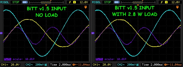
        1.5 version no change on input at 2.8watts output with advanced Scope shots


        https://www.youtube.com/watch?v=2aVN08CYPi4


        Last edited by BroMikey; 10-25-2014, 09:27 AM.

        Comment


        • Originally posted by BroMikey View Post
          1.5 version no change on input at 2.8watts output with advanced Scope shots
          Taking with Paul and Jim the other night, two things we need to investigate:

          1. The air gap in the cores.

          2. The optimum load.


          Both of these guys are hot to look into this device. They both see the similarities to the SERPS device and feel this may be the avenue to pursue to give us the same effect without all the switching electronics.

          The concept Jim mentioned relates a motor/generator with a transformer and he knows how to make a motor be only a motor and a generator be only a generator. The concept is directly applicable to a transformer as well.

          I need to get winding coils...

          Comment


          • Specific Tuning

            Originally posted by Dog-One View Post
            Taking with Paul and Jim the other night, two things we need to investigate:

            1. The air gap in the cores.

            2. The optimum load.


            Both of these guys are hot to look into this device. They both see the similarities to the SERPS device and feel this may be the avenue to pursue to give us the same effect without all the switching electronics.

            The concept Jim mentioned relates a motor/generator with a transformer and he knows how to make a motor be only a motor and a generator be only a generator. The concept is directly applicable to a transformer as well.

            I need to get winding coils...

            Hey Dog-One

            The thing is with putting gaps in your C-core is you get less current draw first and second is faster reversals? Well I don't know why but this gap is found when I take all of my flyback cores out. And it crossed my mind then as I removed the cores from their natural habitat why isn't someone giving gap information? Of course I just caulked it up to those skilled in the arts would know this.

            @Everyone Thanks for the reminder

            In a standard Tv the flyback C-cores use gaps to enhance switching is my guess.


            Here is someone else talking


            "A forward-topology transformer doesn't need any gap since the peak flux density is a function of the applied volt-seconds only; the power being delivered 'through' the transformer isn't a variable (other than its effect on duty cycle). It's only the magnetizing current that moves the core along its hysteresis loop, which doesn't pose any saturation risk if everything is well-designed, since the primary and secondary ampere-turns cancel each other out.

            A flyback transformer doesn't have the ampere-turn cancellation benefit of a forward converter, so the entire 12LI2 primary energy moves the core up its hysteresis curve. The air gap flattens the hysteresis curve and allows more energy handling by decreasing the permeability of the core. You will of course need to add more turns to get your desired inductance compared to no-gap, but you avoid core saturation."

            Last edited by BroMikey; 10-25-2014, 06:43 PM.

            Comment


            • Mind The Gap And Improve Your Low-Power Flyback Transformer Design | Energy content from Electronic Design


              Mind The Gap And Improve Your Low-Power Flyback Transformer Design
              Dec 13, 2009 Glen Cotant | Electronic Design


              The low-power (milliwatt) flyback transformer used in a switched-mode power supply (SMPS) needs to be designed with a gap in the magnetic path for maximum power delivery over temperature. Transformers built on ferrite structures are typically gapped for higher-power storage capability or for large dc currents.

              In low-power or low-dc-current applications, where a machined gap isn’t needed for power or current handling, there still needs to be a gap to stabilize the ferrite’s temperature variation characteristics and provide improved power delivery to the load.

              The flyback transformer is very different from a signal transformer, and not making the distinction can lead to poor performance. Actually, the flyback transformer is a coupled inductor and not a transformer in the true sense.

              In the signal transformer, current flows in the primary and secondary windings at the same time, inversely proportional to the turns ratio of the windings. In a flyback transformer, current flow is restricted to one winding at a time.

              Designing a flyback transformer using a ferrite core that doesn’t have a gap might seem appealing for low-power (milliwatt range), low-current applications. But don’t fall into this trap because it will cause poor performance. The power delivery of the SMPS using this ungapped transformer will be limited.

              This limitation is not apparent at room temperature, normal input voltages, or normal load demand. But it will become obvious at high temperature with low input voltage or increased load demand. Thus, an important aspect of flyback transformer design is to “mind the gap.”

              SMPS OPERATION
              Figure 1 shows a simplified typical SMPS converter using a flyback transformer. A source voltage is switched on and off, by means of a transistor (MOSFET), drawing current through the flyback transformer’s primary.

              When the transistor is on (tON), the current through the primary windings ramps up in proportion to the applied voltage and inversely to the value of the primary inductance. Because of the blocking diode and the polarity of the secondary winding, there is no current flow in the secondary winding at this time.

              When the transistor opens (tOFF), the primary winding current drops to zero, causing the voltages on all of the windings to reverse in polarity. With the secondary polarity reversed, the secondary current can now flow through the forward biased diode. The energy stored in the core transfers to the secondary windings and into a charging output capacitor and the load.

              For the SMPS circuit in Figure 1, a typical current through the primary winding is expressed via a well-known electrical engineering formula using the inductance, voltage, and current relationship:

              The voltage (V) across an inductor winding produces a ramping current (di/dt) with respect to the inductance value (L). Figure 2 shows some typical waveforms from a flyback SMPS circuit (such as the one shown in Figure 1).

              Peak current in the primary winding is the magnitude that the current reaches at the end of the transistor time on (tON). Figure 2 shows this as the maximum value of current (ILp) (after ramping up at the slope value of di/dt) as expressed by Equation 1.

              When a constant value of voltage is applied across an inductor winding, the current ramping will be steeper (ramps faster) for a lower value of inductance and flatter (ramps slower) for a higher value of inductance. Inductance value and ramping current are inversely proportional.

              High values of di/dt (low inductance) result in added ripple currents that need to be compensated for or filtered out. However, low values of di/dt (high inductance) result in less energy stored and transferred to the load (since energy is directly related to the square of the current). These dynamic situations can be compensated for with feedback to alter the pulse width to the switching transistor, but there is a limit due to the switching frequency.

              In pulse-width mode (PWM), the (tON) period is manipulated by a pulse-width controller device, which sends a signal to the gate of the MOSFET in Figure 1, based on feedback circuitry from the load. In pulse-frequency mode (PFM), the frequency of the switching is altered to accommodate changes in load demand. The feedback to the control circuit is from load voltage or current sensing devices.

              These control circuits are designed around the assumption that the inductance of the flyback transformer is within specified values. When the inductance value varies beyond the specified limit, the power delivering capability of the SMPS suffers.

              FLYBACK TRANSFORMER DESIGN
              A standard practice for designing a flyback transformer is to evaluate the energy needs of the SMPS and, using information from the ferrite manufacturer, choose a ferrite platform that will accommodate these needs. Ferrite cores offer self-shielded shapes with bobbins that are easily wound, an alternative to powder iron toroids or E cores. When the inductance value is calculated by the power-supply designer and the maximum current is then known, the stored energy is calculated by:

              In many SMPS applications, energy and power are significant, and large ferrite shapes with gaps machined into the magnetic path must be used. But in today’s world of portable, low-power devices, the energy requirements can be minimal and small ferrite shapes (i.e., EP7) are used for the flyback transformer design. In some instances, the requirements are so low, a gap is not needed for energy purposes.

              For example, a 300-µH inductance value that must allow 100 mA of average current has an I2L power requirement of 3 × 10⁻⁵ joules. Using a ferrite manufacturer’s data on energy versus gap size, such as the tabulated data from a Ferroxcube graph in Table 1, an EP7 ferrite size with a gap of less than 0.1 mm is specified. This gap size is the lowest value listed, essentially a non-gapped value. Unless the ferrite mating surfaces are polished, this gap distance is the average physical distance due to uneven surfaces of non-gapped cores.

              Specifying a ferrite core without a gap has its advantages in the design of many magnetic components. But the flyback SMPS power capability will suffer if an ungapped ferrite core is used. For non-flyback, non-inductor applications, one advantage of an ungapped magnetic path is that it allows a minimum number of turns of copper wire to achieve a specific value of inductance.

              When a gap is introduced into the ferrite core’s magnetic path, the overall ferrite structure’s ability to produce a specific inductance using a minimum number of wire turns (also called the AL value) is changed significantly. If one machines a gap in the core, the needed turns will increase, and this would increase the winding resistance.

              These two characteristics, machining a gap (more cost) and adding resistance (more losses), are typically unattractive to transformer manufacturers. So to the novice designer, eager to produce a low-cost, seemingly efficient flyback transformer, the use of an ungapped ferrite is at first appealing. However, the lowpower ferrite flyback transformer should in almost all applications be designed using a gapped ferrite shape.

              FERRITE THERMAL CHARACTERISTICS
              Ungapped ferrites for low-power flyback transformers aren’t a good choice mainly because of the fluctuation in inductance over temperature. Figure 3 illustrates typical AL values (inductance producing capabilities per turn squared) of gapped and non-gapped ferrite cores over temperature, based on the data in Table 2. Notice the large variations in the ungapped ferrite as compared to the almost constant response of the gapped ferrite.

              A flyback transformer, using an ungapped ferrite with an inductance value of 300 µH at room temperature, would have an inductance value of 170 µH at –40°C and 570 µH at 120°C. With a gap, the values of inductance are 285 µH at –40°C and 311 µH at 120°C. This is within a 10% tolerance over the extended temperature range with a gapped ferrite versus about a 200% variation with an ungapped ferrite.

              IMPROVED SMPS POWER CAPABILITY
              At high temperatures, the inductance of a non-gapped flyback transformer increases significantly. An increase in the inductance has the same effect as a drop in the input voltage, as seen in Equation 1. Much has been written about minimum input voltage for SMPS design, as it is a critical value. Minimum input voltage (or high flyback transformer inductance) and maximum output load increase the power demand on the SMPS.

              These conditions cause the ON time (duty cycle) of the switching to increase, as the circuit works to feed more current and power to the load. Most SMPS designers use minimum input voltage, minimum output impedance (maximum load), desired efficiency, and maximum duty cycle time to calculate the inductance value of the flyback transformer. A transformer may be designed to meet this value at room temperature. But without a gap, trouble arises when the temperature increases.

              The discontinuous mode flyback SMPS has a maximum duty cycle. Once that limit is reached, the SMPS cannot produce any further power from a constant input voltage. The ungapped flyback transformer will reach this limitation when subjected to high temperature, low input voltage, or increased power demand.

              In discontinuous mode, all of the energy stored in the primary is allowed to disperse into the secondary before a new cycle starts. Figure 2 shows this “dead” time as a period where there is no current flow in either the primary or the secondary.

              Continuous-mode design allows a new cycle to start while there is still energy in the transformer. Additional circuitry can be employed to create a flyback SMPS that will transition from discontinuous into continuous mode, but this adds cost. Figure 4 compares the gapped flyback transformer waveforms to the non-gapped flyback transformer at high temperatures. Both the gapped and non-gapped flyback transformers had the same primary inductance at room temperature.

              The current waveform for the gapped flyback transformer reaches a higher peak value in less time, indicative of its lower inductance value and higher di/dt slope value. There is a dead time of zero current before the next cycle starts keeping it well within the discontinuous mode. The waveform for the ungapped flyback transformer does not reach the needed peak current, because at higher temperature its inductance has increased, lowering its di/dt slope value.

              To remain in the discontinuous mode, the time ON has to be restricted so all the energy stored can be dissipated into the load (secondary). The ungapped flyback transformer SMPS is unable to provide the same amount of power as the gapped flyback transformer SMPS when temperature increases.

              Remember that flyback transformers aren’t truly transformers, but coupled inductors that need stable inductance at high temperatures to deliver maximum power. Trying to save 10% to 20% of the cost of a gapped ferrite by leaving it ungapped can lead to poor power delivery performance at high temperatures, low input voltage, and high power demand. The ferrite flyback transformer needs to have a gap. When it comes to ferrite flyback transformer design, be sure to “mind the gap.”

              Comment


              • Originally posted by BroMikey View Post

                @Dave

                Did you replace your wire wound resistor with a carbon type. And did you loose your phase angle? Time for tuning? What happened?

                Mikey
                I don't think the guy that produced the video that I referenced is a disinformation agent at all. He is reporting the same results that I have seen.

                I'm using 10 - 1 Ohm carbon resistors in parallel to get 0.1 Ohm of resistance. This greatly reduces any stray inductance. As I perform power calculations for various loads at various frequencies, I always seem to fall short of 100% efficiency. This could be for any number of reasons. My cores might not be good for this, my coil impedances might not be correct, improper load matching, or not operating at the optimum magnetizing force. All of these things could play a critical role in why I am not seeing anything. However, I've tried varying these parameters with my 3r1 cores and haven't seen it make much of a difference. I always see an increased positive power factor when I load the transformer. The closer to impedance matched the load is, the more power it draws from the primary. I have yet to see my phase shift be unaffected between a loaded and unloaded secondary.

                I was looking back through some BiTT videos last night and noticed that most of the replications, that show the phase shift remain stable for loaded and unloaded, are using a much higher inductance primary than that of the secondaries. Currently, I'm following Bill's line of logic where my primary is of a small inductance compared to the large inductance of the secondaries. Maybe this will be a new avenue for me that proves to be fruitful.

                Dave

                Comment


                • Design Guide

                  http://www.google.com/url?sa=t&rct=j...KphJww&cad=rja

                  Comment


                  • Iron Cores

                    Originally posted by Web000x View Post
                    I don't think the guy that produced the video that I referenced is a disinformation agent at all. He is reporting the same results that I have seen.
                    Dave
                    The guy has IRON for a core in every square inch of his Transformer.

                    I think we need to stop right here, because to jump over this detail, speaking of this other guys iron core in the same light as a ferrO cube is like saying marshmallows and white rubber balls are pretty close to the same thing.

                    If we are not going to establish the foundation for this work then others will be mislead. I can't stress the significance of core material as specified by the inventor first and of course so many other highly intelligent individuals using that principle to recreate their own version.

                    I understand the way the mind works when reviewing video content in the privacy of the mind. Looking back I think some will confuse data put forth by replicators of the BiTT/SFT2.

                    Make no mistake, thane has never one, I repeat NEVER ONCE used an all iron core to demo his Bi-Toroid. In standard 60hz mode we see a possibility that the primary MAY use a less permeable core material such as iron but this is never declared and even if it is said to be iron in the primary the other portion or the bulk of the complete core material is of a higher permeability.


                    So now that we have established that the nice well meaning guy in the video has the wrong setup, how can we call it the same?

                    And then say we get all the same results from a completely different material.

                    Look at the recent video I just posted with the JLN BiTT. He turns it over so we can see the bottom. That material used in the secondaries is NOT and iron core. Look at the primary. Look at the material. The first thing our minds say is that the primary MUST be a transformer with the top bar cut off so it is open to attack to the secondaries.

                    So we assume that it is an iron core for the primary and since it is a low resistance flux path fits the design criteria. This is a false assumption. JLN Labs has a primary core material that is rewrapped with 3-4 times as much wire till it looks like it is going to burst.

                    Look at it. Why did he put so much wire on that core. Why does it take so much more wire to the point that the entire spool of a single coil takes up the same room as a secondary and primary normally takes up? Why?

                    Sound familiar? The reason why is that the core material is not pure iron as we may have to quickly concluded. Gaps also help high frequency switching so how in the world is WHTS HIS NAME going to gap his IRON transformer?

                    How is an IRON transformer the same as THANE's core material?

                    A statement like this shows that we do not understand the experiment. Even the best of us make blunders like this.

                    We must follow the instructions of the core material and NEVER compare IRON cores with our setups. They are not going to respond the same way.

                    Mikey
                    Last edited by BroMikey; 10-25-2014, 08:45 PM.

                    Comment


                    • The effect

                      Originally posted by Web000x View Post

                      I'm using 10 - 1 Ohm carbon resistors in parallel to get 0.1 Ohm of resistance. This greatly reduces any stray inductance. As I perform power calculations for various loads at various frequencies, I always seem to fall short of 100% efficiency.


                      Currently, I'm following Bill's line of logic where my primary is of a small inductance compared to the large inductance of the secondaries. Maybe this will be a new avenue for me that proves to be fruitful.

                      Dave

                      Follow the effect.

                      Sounds like a gap is in order. Bill is running approx 3khz and tuned for this frequency and so you can not say you are following Bill in this respect. Also Bill used Metglas.

                      I can't think of your exact frequency but I think it was 20-30 times higher than Bill's 3khz, so this is way higher. Not saying that we couldn't reinvent the BiTT to operate at the region.

                      In my frequency work with harmonics you see more power at the low end. Let's look at Bill's demo. First he runs a standard transformer at 1200cps
                      then he runs his BiTT at 3200cps.

                      Also look at Thane's demos at 60hz showing the proper phase angles and effects. If the effects are there all that is left to do is vary the frequency and tune with caps.

                      Look at Mr Clean's videos his best experiment running pulse DC is at 2900cps.

                      You must be to high. Use and air gap to ensure that saturation does not persist and lower frequencies with tuning caps for the lower ranges. Start at 250hz and find the effects at every frequency.

                      I know it is a long drawn out documentation to do so many frequencies and cap resonant tunings. In almost every frequency range there will be positive results yet not optimum.

                      For instance at 1000cps the BiTT may increase in efficiency over the 120cps setting and so on til we get to 5000cps.

                      If ultra high frequency operation is desired such as 200,000cps then yes i would say go for the exotic high cost custom cores. The design energineers at ALPHA DIRECT can calculate both costs and core material changes.

                      I think the expense out weighs the benefits.

                      These are my personal viewpoints on the subject.

                      I need to find some carbon resistors as well. It seems like all I can find are 1 watt carbon for the largest size.

                      Hang in there, this stuff requires all of your experience and then some. Thanks to guys like Dog-One gathering facts from Bill,Jim,Paul we can keep from drowning in wonder.

                      They are on our side, on the side of the average Joe experimenter.


                      This is our advantage. Thanks Guys

                      Mikey

                      Comment


                      • I'm very aware that core material is going to play a key role in function of such a device. All that I am saying is that, MY RESULTS are very SIMILAR to the RESULTS IN THE VIDEO. I went on to say that I'm probably missing something and is the reason I'm not seeing anything unusual. I do believe that Thane Heins is a capable man and has shown us a novel effect. Remember, what doesn't work is just as important to know as what does work.

                        And yes, I am following Bill's line of logic. (Small Primary, Big Secondaries, Square BH Curve) Just because I posted a video a while ago showing that I was operating at higher frequencies than Bill, doesn't mean that I haven't sat down and tediously taken measurements and calculated results for ALL FREQUENCIES that the impedance of my primary winding permits. I have run tests from 30 Hz all the way up to 200 kHz. The BH curve of my material is very square, much like Amorphous Core Material of Metglas.

                        Where did you catch Thane discussing his core material? I'm interested in looking into this.

                        Dave

                        Comment


                        • Testing BH curves.

                          Originally posted by Web000x View Post
                          I'm very aware that core material is going to play a key role in function of such a device.


                          I have run tests from 30 Hz all the way up to 200 kHz. The BH curve of my material is very square, much like Amorphous Core Material of Metglas.

                          Where did you catch Thane discussing his core material? I'm interested in looking into this.

                          Dave
                          Hey Dave

                          I saw that video in the few he has on his you-tube channel I think. He goes on to say that Permalloy can vary in permeability and that the primary could have a core material of 100x greater resistance.

                          But this is based on 60hz I believe as Thane is showing only the basis of his findings at an easy frequency for everyone to get.

                          I am glad to hear you say that you have run the figures. I never saw any posts like this. So are you at COP .5? You know like standard EM EE designs?


                          I saw an amp on ebay for under $15 a mono single channel good for 25 watts rated higher for the max.


                          I think a gap might help your rig. Did you try any gaps? Or loads that vary resistance with power level increases? This may help you.

                          BroMikey
                          Last edited by BroMikey; 10-31-2014, 06:54 AM.

                          Comment


                          • Originally posted by BroMikey View Post
                            I think a gap might help your rig. Did you try any gaps? Or loads that vary resistance with power level increases? This may help you.
                            What Jim told me is the gap lowers the inductance and provides an avenue for outside energy to enter the system. He also studied Tesla and noted that Tesla discovered the gap must be adjustable to track the impedance of the load. So if you have a fixed gap, you must have a fixed load. If you have an adjustable gap, you can hunt for the most optimal combination where the COP climbs to its peak. And if you're really good, you can automatically adjust the gap to track your load dynamically.

                            I get the feeling Jim really understands this phenomena and Paul is learning quick. Jim said to me straight away, if you keep after it, you'll figure this all out for yourself. That and his hints, I think we can do this. I think a looper is possible. We just need to focus on what's important. We need to figure out how to find the sweet spot, which means knowing when you are too high or too low with each specific parameter. We get a protocol that tackles that issue and we're home free.
                            Last edited by Dog-One; 10-25-2014, 11:37 PM.

                            Comment


                            • Serps Call in

                              I missed the SERPS call in time with Jim and Paul

                              Thanks for letting me know these guys are looking over our shoulder incase we need more help. We can always use experienced help.

                              Excellent facts to share Dog-One great to have you around, looks like you are collecting the gold from these guys who are far more advanced.

                              Mike

                              Comment


                              • Just a few comments

                                Hi Mike, I just want to jump in and add a few comments.

                                1. I'm glad you moved your ammeter where Dave suggested. The new diagram (of 3 days ago) shows the meter where it should be.

                                2. I have been following this thread with great interest since you first started it and I want to encourage you to stick with your plan. You have been clear and your replication is easy to follow. The photos are a big help. I think most replicators will be able to follow along with what you did and are doing.

                                3. If I am reading you correctly, adding a gap in the magnetic "circuits" caused a drop in COP. You might want to repeat that experimentally. Try it both ways, keeping everything else as same as possible. You can't make the gap less than zero, but you need to know whether the gap improves performance, or not.

                                4. There are many other things that can be varied to find out what works better and what makes things worse. One of those, of course, is the frequency. As long as you are staying with power from the power company you will be stuck at 60 Hz. If you feel so inclined, switch from power company power to a variable frequency sine wave generator so you can vary the frequency up and down slightly and compare COPs.

                                5. Just a note: I also see you adjusted the attached capacitors to improve the COP.

                                6. If I may suggest one caution it would be this. Trust what your experiments are telling you. Don't listen to abstract criticisms that depend on theory. Theory has led too many down a wrong path. Starting with COP of 1.27 or 1.28 is nothing to scoff at. From my side of the table, I want to read what works so my build will also work properly.

                                7. Another idea: I think it would probably be easy to rearrange the load bulbs to vary the resistance and current. For example, you could change from a 3 by 2 arrangement to a 2 by 3. Later you might want to power everything from a battery and have a battery charger as the load. Don't jump to that stage prematurely. The idea is that some will trust the voltage reading on a charged or partly depleted battery when they won't trust an AC power reading because of the imperfect sine wave being measured.

                                8. Don't do anything solely based on my ideas. You do what you think is best and best wishes to you.
                                There is a reason why science has been successful and technology is widespread. Don't be afraid to do the math and apply the laws of physics.

                                Comment

                                Working...
                                X