Announcement

Collapse
No announcement yet.

Self Charging ?

Collapse
X
 
  • Filter
  • Time
  • Show
Clear All
new posts

  • #16
    Originally posted by Slider2732 View Post
    Yeah, while he was talking I was thinking of parlour tricks, slight of hand type of thing.
    That could well be doing the chap a huge disservice though.
    It prompted my own cap bank foray though, and, perhaps some weird results. That first battery has definitely held at 4.25V now, the second battery is being trialled.

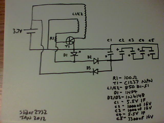
    Here's the circuit i'm using:


    Mistake on the diagram - D1 is the LED, D2 is a germanium 1N94 type.
    Maybe the D3 is needed, maybe not.
    It'll run on the caps alone for a minute without the D3, but will charge the caps very slowly and possibly pass energy to the battery with it in place.
    If nothing else, many people will have homebuilt SSG's and can connect things up to try the idea out
    Slider,
    the only way I get this to fire is if I reverse the trigger coil leads. are you sure the top of the coil goes to the emitter and the bottom to the base?
    I'm using everything similar to yours except battery and transistor, been swapping out different transistors to see if I can get the effect to show up.
    my coil keeps warm - no where for the energy from the power coil to go.

    Thanks,
    Patrick
    Comment


    • #17
      Ah, no...the windings are regular. I stuffed up on the schematic drawing conventions.
      The power wire outer goes to the positive rail.
      The power wire inner goes to transistor Collector.
      The trigger wire outer goes to 100ohm resistor.
      The trigger wire inner goes to the negative rail.
      I'm a lot newer to these circuits or indeed schematics of them than you are and respect that you've tried the circuit

      Do note though, that I used a germanium as D2. That's because of the 0.245V drop across it and relates to recent crystal radio work. Is it in fact 'better' than a 1N4148 or other diode ? no idea.
      The circuit will run with no caps, just the regular battery power.
      When 'correct', the D3 can be omitted and the caps directly connected to the positive rail, with no battery. Like that, the LED will fire and the circuit run for a few seconds, the rotor will slow and the LED gain brightness as it does so. Without caps or battery, the circuit won't fire (DadHav once showed a Bedini circuit generating power, when he spun up the rotor with a Dremmel type tool).
      The bi-filar is of the same gauge for both windings, 26 gauge, actual R-Charge wire straight off one of their spools.
      The windings were checked for continuity.

      The LED replaces the normal 1N4007, the Collector only fires the power winding and doesn't share output through a diode to charge a secondary battery, as normally done.
      Instead, the charging comes from the Emitter and LED throughput.
      If you get the LED to flash and visually show the firing, then that's what you want to see. The LED method is a furtherment of I think it was Neight's method...where he mentioned to put one across the trigger winding to show a circuit is firing. In my method, the LED also suits the run voltage and becomes an indicator of charging power. The LED brightness is dependent upon the amount of transistor Base leg feed from the trigger coil.


      ------------------------------------
      A chap on the comments section of my uploaded vid mentioned a required safety aspect. That heads up is very important.
      Li-ion's normally have a protection circuit, in the R/C hobby at least its known as the LVC. That Low Voltage Cutoff circuit protects the cell from over discharge. The circuit also (but not always as an inbuilt function) will protect from over voltage charging too.
      Lithium is highly volatile when abused...the main safety area is for Lithium polymer cells, usually shortened to li-po. These can and have caught fire seemingly spontaneously - but themselves do need to have their aluminium covering sliced, be overcharged, shorted out, discharged at ridiculously high levels, charged at too high a rate or similar to fail in such a way. Such cells obviously should be handled with care (i've never understood why they always have such flimsy aluminium foil around them, but love the fact that they do because they are incredibly light, for micro aircraft homemade aircraft).
      Li-ion are a lot safer...i've never had an issue with them. BUT they do have lithium within.
      Li-ion cellphone batteries will also charge with LVC circuit in place on a hobby grade Ni-MH charger - that's how I started out in powered flight.
      As an aside, if any li-po or li-ion reads 0.0V on a voltmeter, it will be the LVC circuit that has failed. You can cut it off and replace with a same ratings cell LVC without issue. Have done it plenty of times, but it is not advised, unless you always use a metal can to store the batteries and emlpoy common sense !
      None of the above is advised for those not familiar with such batteries , ever !
      Always use a thick metal can to store anything made with Lithium.
      --------------------------------------

      This does, however, bring up radiant charging. We know that lead acid batteries don't heat up, we know that the systems and energy work differently - I know that a li-ion battery will charge radiantly with no LVC and I know that previously crapped out circa 2003 cells can return to peak performance.
      Please do bear in mind that I would rather have safety issues than any of you chaps, let me be the foolish one !
      Last edited by Slider2732; 01-28-2012, 10:36 PM.

      Comment


      • #18
        Slider2732

        Again liked your video. I have also brought back to life a previously dead lithium
        ion laptop battery with radiant charging. I had heard that it was supposed to be
        tricky. I guess I lucked out. Thanks for the additional information on these type
        of batteries.

        George

        Comment


        • #19
          Originally posted by Slider2732 View Post
          Ah, no...the windings are regular. I stuffed up on the schematic drawing conventions.
          The power wire outer goes to the positive rail.
          The power wire inner goes to transistor Collector.
          The trigger wire outer goes to 100ohm resistor.
          The trigger wire inner goes to the negative rail.
          I'm a lot newer to these circuits or indeed schematics of them than you are and respect that you've tried the circuit

          Do note though, that I used a germanium as D2. That's because of the 0.245V drop across it and relates to recent crystal radio work. Is it in fact 'better' than a 1N4148 or other diode ? no idea.
          The circuit will run with no caps, just the regular battery power.
          When 'correct', the D3 can be omitted and the caps directly connected to the positive rail, with no battery. Like that, the LED will fire and the circuit run for a few seconds, the rotor will slow and the LED gain brightness as it does so. Without caps or battery, the circuit won't fire (DadHav once showed a Bedini circuit generating power, when he spun up the rotor with a Dremmel type tool).
          The bi-filar is of the same gauge for both windings, 26 gauge, actual R-Charge wire straight off one of their spools.
          The windings were checked for continuity.

          The LED replaces the normal 1N4007, the Collector only fires the power winding and doesn't share output through a diode to charge a secondary battery, as normally done.
          Instead, the charging comes from the Emitter and LED throughput.
          If you get the LED to flash and visually show the firing, then that's what you want to see. The LED method is a furtherment of I think it was Neight's method...where he mentioned to put one across the trigger winding to show a circuit is firing. In my method, the LED also suits the run voltage and becomes an indicator of charging power. The LED brightness is dependent upon the amount of transistor Base leg feed from the trigger coil.


          ------------------------------------
          A chap on the comments section of my uploaded vid mentioned a required safety aspect. That heads up is very important.
          Li-ion's normally have a protection circuit, in the R/C hobby at least its known as the LVC. That Low Voltage Cutoff circuit protects the cell from over discharge. The circuit also (but not always as an inbuilt function) will protect from over voltage charging too.
          Lithium is highly volatile when abused...the main safety area is for Lithium polymer cells, usually shortened to li-po. These can and have caught fire seemingly spontaneously - but themselves do need to have their aluminium covering sliced, be overcharged, shorted out, discharged at ridiculously high levels, charged at too high a rate or similar to fail in such a way. Such cells obviously should be handled with care (i've never understood why they always have such flimsy aluminium foil around them, but love the fact that they do because they are incredibly light, for micro aircraft homemade aircraft).
          Li-ion are a lot safer...i've never had an issue with them. BUT they do have lithium within.
          Li-ion cellphone batteries will also charge with LVC circuit in place on a hobby grade Ni-MH charger - that's how I started out in powered flight.
          As an aside, if any li-po or li-ion reads 0.0V on a voltmeter, it will be the LVC circuit that has failed. You can cut it off and replace with a same ratings cell LVC without issue. Have done it plenty of times, but it is not advised, unless you always use a metal can to store the batteries and emlpoy common sense !
          None of the above is advised for those not familiar with such batteries , ever !
          Always use a thick metal can to store anything made with Lithium.
          --------------------------------------

          This does, however, bring up radiant charging. We know that lead acid batteries don't heat up, we know that the systems and energy work differently - I know that a li-ion battery will charge radiantly with no LVC and I know that previously crapped out circa 2003 cells can return to peak performance.
          Please do bear in mind that I would rather have safety issues than any of you chaps, let me be the foolish one !

          OK, we have the coil part straightened out.
          what about the caps... you have c2-5 in series and then all 4 in parallel with c1.
          however...
          their polarities are reversed?
          so c2's neg is connected to c1's +
          and c5's + is connected to c1's neg is that on purpose? this makes my caps work backward.

          I can get d1 to light only if I reverse the direction of your drawing.
          does this mean the other 2 diodes are also reversed?

          I have it working better now, the coil does not warm as much so I'm only asking to make sure I replicate it correctly. I do have the germanium diodes left over from the original joule ringer days :-) I know I'm pretty close, the caps charge to 10+volts.


          Here is a good explanation of why John's (dadhav) SSG stator generated power:

          Pulse motor and Bolt's Amplified SSG short - YouTube

          his geometry is wrong for the SSG, HOWEVER, out of a brilliant mistake comes fantastic innovation.
          if you pay attention to the timing of this amplified short, you are one giant leap away from buck-boost/magamp timing on the SSG

          I'm still working on replicating your project. I like it when others succeed at replications so I will try hard with this one.
          Thanks for sharing it.

          Patrick

          Comment


          • #20
            addition of caps

            Slider,
            maybe... could you take this picture - I removed the charge battery can you add your diodes and caps?
            I read your discription above and I do not have enough common sense to piece it together
            Thanks,
            Patrick
            Attached Files

            Comment


            • #21
              Will do and repost later tonight...it may be very late though LOL
              Probably the same as many folks, I build, solder, resolder, swap a component or two. Then, cludge along to follow the now messy soldering to create a schematic. What i've done before now is to forget simple things like LED polarity swaps ! I think i've posted about 3 schematics ever.
              So, it's very much a good idea to redraw, follow the actual first build again and at the same time aid your replication.
              *edit* wait a sec, you have the trigger coil connected to the positive rail, instead of negative rail ?


              The caps are one large one to run from and several tied end to end in series. By PMMG4HYBRID's explanation, the smaller ones should shuttle power around and fill quite quickly, the larger one soaks quicker than the battery. The final result is a battery which is doggedly slow to respond compared to the caps...allowing it to charge when it can.
              In my first circuit, there is another 5.5V 1F cap...which i'm debating whether to remove. However....I believe the rule is to leave a first circuit completely alone and replicate with another, that includes the changes.
              My original idea, was to time charging 'naturally', using the lighting of the LED as an allower of power back through to the battery - making charging out of phase with the power draw. Far easier to employ than complicated circuitry.
              If you hook up a battery to the circuit you'll see zero draw until the circuit runs. That same zero draw condition exists, I believe up to now, between moments of an SSG firing. It's the relaxation time and charging opportunity time. So, perhaps a delay line would work even better.
              Anyway, just thoughts.

              If your LED lights correctly and you're charging the bank to 10V, then give her a whirl and see what happens
              Nothings set in stone here and if any modifications you make to the circuit work out better, then 'jolly good show' !
              The White Lion name in the video description is just something of an identifier name, to theme with the White Crow of last year. It's a play on Li-Ion. I know you don't go for naming things by peoples names, so perhaps as a project name the White Lion would work.
              That is, indeed, if there is a project to made from these rewired SSG cap dumping/charging/running experiments

              The coil should run cold, the transistor too.
              A note about transistor power requirements and heating - i've just got a 2N2222A version running.
              The coil is an 850 wind again, similar dimensions to the other. Nothing gets warm. The rotor is the same one off the other circuit, running at a comparable speed
              Last edited by Slider2732; 01-29-2012, 05:26 AM.

              Comment


              • #22
                Originally posted by Slider2732 View Post
                Will do and repost later tonight...it may be very late though LOL

                *edit* wait a sec, you have the trigger coil connected to the positive rail, instead of negative rail ?
                that pic is from a solid state SSG schematic, I forgot to move the connection back to the neg rail. :-)

                I should note, there is no heating or current draw until I spin it up, at these low voltages the transistor does not heat up, but the coil does. I know I have those caps and diodes hooked up wrong some how.

                thanks for any help,
                Patrick

                Comment


                • #23
                  I'd draw the schematic on paper anyway, because I don't have a printer with good cartridges.
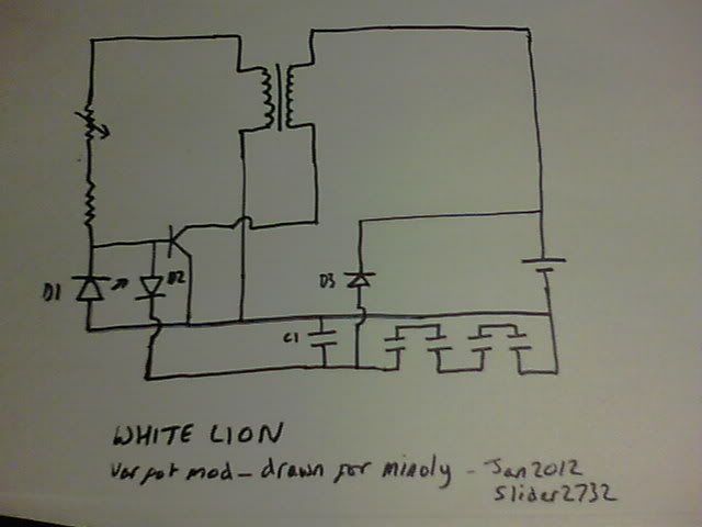
                  Well, I hope this will help for now -

                  D1 - LED - Positive to Negative rail, Negative to Base of transistor (idea came from Slayer exciter).
                  D2 - 1N94 Germanium - Positive to Base of transistor, Negative (black line) to C1 Positive.
                  D3 - 1N4148 - Positive to C1 Positive, Negative (black line) to Positive supply rail.

                  Interesting about the solid state SSG. When I first tried to make one some while ago, I couldn't see how the transistor was to obtain a positive voltage. So I connected how you drew up the circuit above.
                  The coil made a high pitched squeal, which could be altered in frequency with the 1K pot.
                  It would burn holes in the variable pot (with smoke and that less than thrilling sight of a bright orange glow inside the pot housing - the only pot smoking that's been done in our house lol) and the coil would warm up pretty quickly too...but...would still charge a battery !
                  Needless to say, the wheel didn't move anywhere though.

                  Comment


                  • #24
                    Here ya go
                    Included is the var pot mod that was drawn on your diagram, as per an SSG.
                    C1 has its positive at the bottom, negative at the top to join the negative rail.
                    The other caps are in series, beginning with positive connected to C1 positive. Then - to +- to +- to +- and out to the negative rail.
                    Looking at it redrawn like this, improvements could be made. Like, running to the caps from across the LED.

                    Comment


                    • #25
                      Originally posted by Web000x View Post
                      Here is another video that shows the significance of the motor he is using.
                      STARGATE MOTOR FULL DEMO - YouTube

                      Dave
                      Very cool stuffs. I've seen this phenomena from time to time and think there is something interesting about this. The magnetic field do some saturation making more current flow, but efficiency get a good boost. I think it can go over efficient. This is promising because it is simple to replicate and the motor-generator made easy for looping setup. I'm thinking using electromagnet jacket around the motor.

                      Comment


                      • #26
                        Yeah, I think that the simple nature of this and little, if any, expenditure make it very much worthwhile.
                        While it's commonly accepted (from my understanding) that the case of a motor adds to flux and forms somewhat of a containment for the magnetic fields...that's not to say that stonking neo's at exactly the right points can't add to it. The expectation would be extra current draw, which, apparently doesn't seem to be the case with some employments of that idea.
                        In own tests, within radio controlled flight, I simply saw extra current draw for increased RPM's. But, that was with using 6mm 'pager' type motors.
                        Other experiments have included what are called milligram brushless motors, where the coils are built around say a dress pin, with the cylinder magnet from a 6mm motor affixed onto the pin. Whether those such motors could benefit from little SMD capacitors in series etc would be intriguing. I've never tried running one as though it was a Bedini type system.

                        One thing - don't make my mistake of a couple of days ago and try to search for 'how many mA are in a Farad' LOL

                        Comment


                        • #27
                          Originally posted by quantumuppercut View Post
                          Very cool stuffs. I've seen this phenomena from time to time and think there is something interesting about this. The magnetic field do some saturation making more current flow, but efficiency get a good boost. I think it can go over efficient. This is promising because it is simple to replicate and the motor-generator made easy for looping setup. I'm thinking using electromagnet jacket around the motor.
                          STARGATE MOTOR FULL DEMO - YouTube

                          The big question with this setup is.... Does the motor produce the same
                          torque on 12 volts (with extra magnets) as it does on 24 volts (without extra magnets) ?

                          Even though he can make it rotate faster that doesn't mean it will have more
                          torque. Tests on an unloaded- free wheeling motor are virtually useless. I
                          would like to see the test repeated with the motor under full load, it's a 125
                          watt motor but he is testing it with no load drawing about 14 watts on 24
                          volts.

                          He says he will see if the motor can reach it's full potential, I say balony, the
                          motor was unloaded, to see if it can get to it's full potential it needs to be
                          tested under full load, or what good is it. Where is the load for goodness
                          sake.

                          At the end you can hear how slowly the motor is gaining rpm, with a load
                          attached I doubt it would have the torque to get anywhere near the rpms he
                          is showing with no load on the motor.

                          You can hear the extra noise it makes when it has the extra magnets so I will
                          guess it will also wear out quicker with the extra magnets as well.

                          Motors are designed to drive a load not to free spin. Basically he hasn't shown
                          the motor working he has shown it at idle. Looks like a gimmic to me.

                          He's got plenty of gear why not show it driving a small generator or something
                          for some load at least.

                          Cheers

                          Comment


                          • #28
                            Originally posted by Farmhand View Post
                            STARGATE MOTOR FULL DEMO - YouTube

                            The big question with this setup is.... Does the motor produce the same
                            torque on 12 volts (with extra magnets) as it does on 24 volts (without extra magnets) ?

                            Even though he can make it rotate faster that doesn't mean it will have more
                            torque. Tests on an unloaded- free wheeling motor are virtually useless. I
                            would like to see the test repeated with the motor under full load, it's a 125
                            watt motor but he is testing it with no load drawing about 14 watts on 24
                            volts.

                            He says he will see if the motor can reach it's full potential, I say balony, the
                            motor was unloaded, to see if it can get to it's full potential it needs to be
                            tested under full load, or what good is it. Where is the load for goodness
                            sake.

                            At the end you can hear how slowly the motor is gaining rpm, with a load
                            attached I doubt it would have the torque to get anywhere near the rpms he
                            is showing with no load on the motor.

                            You can hear the extra noise it makes when it has the extra magnets so I will
                            guess it will also wear out quicker with the extra magnets as well.

                            Motors are designed to drive a load not to free spin. Basically he hasn't shown
                            the motor working he has shown it at idle. Looks like a gimmic to me.

                            He's got plenty of gear why not show it driving a small generator or something
                            for some load at least.

                            Cheers
                            It's true that the motor is operating at no load, but we can identify loading with friction alone. If the motor running at 3000 rpms, energy dissipation for bearing friction is at a value. If it runs at 6000 rpms, then there would be more energy dissipation.

                            Furthermore, it would makes sense that torque increased. Suppose we energize a coil in space. There would be no movement (no torque as this is the armature). Now if we put a magnet next to the coil as stator, there would be torque. The stronger the magnet, the stronger the torque. The problem with saturation can be overcome in my opinion.

                            Comment


                            • #29
                              Originally posted by quantumuppercut View Post
                              Very cool stuffs. I'm thinking using electromagnet jacket around the motor.
                              Hi Quantum

                              in my DC MAGVERTER USING A ROTOR FROM A VACUUM CLEANER

                              I INSTALLED SOME NEODYNE MAGNETS BESIDE THE WINDINGS INSIDE THE ROTOR AND THIS SPEED UP ONCED ENERGIZED WITH 12 V DC AND EXTERNAL RING MAGNETS AROUND THE ROTOR

                              TOTOALAS

                              Comment


                              • #30
                                Totoalas,

                                Comment

                                Working...
                                X