Announcement

Collapse
No announcement yet.

My Motors got me to Tap into Radiant Energy

Collapse
X
 
  • Filter
  • Time
  • Show
Clear All
new posts

  • There are many missing links here, usually your facebook links, UFO, but also some posts where you say "here is a clearer schematic" but there is no picture in the post.

    I see a secondary coil being mentioned a lot but, so far, no pictures.

    I am only on page 22, will i discover all these things as i read on or has anyone put all this information into a single document yet ?


    Thanks,

    Comment


    • Originally posted by JohnStone View Post
      Ufo requested for his current setup a four phase oscillator.
      Post
      Post
      I threw some components into the circuit and ask for discussion. It is what I intend to build.

      The reason for using a microprocessor is because the circuit with logic ICs is lots of wires to draw and one use only. A micro is much more precise and versatile to use.
      @Lester: Some suggestions for i.e. snubber circuit? Suggestions for additional protection?
      @Nico: Arduino connected correct? What about modified program? Where did you connect your POT / LCD exactly?

      TBD:
      • 555 NMOS (slow but 200mA source sink at output) or CMOS (fast but 8mA only) - needs to be tested
      • Control for dead time and frequency: Pot, digital pot or by simple terminal program from PC (USB)
      • Display required?
      • Option for current measurements required?
      • Use of reset at pin at 555 in order to prevent unintended firing of FETs while program downloed and aother actions.


      With some additions (voltge feedback) this circuit can peform as SMPSU - not high end precision PSU but suffitient in order to control the voltage for our loads from battery stack or welder. It depens on your requirements and your setup.

      JohnS
      I pondered on this circuit for some days and I confess it was posted too hasty. It is good for low scale FET applicatrions but owns some uncertainities and limits. At serious applications like driving 56 frame any failure sacrifieces not a single FET on desk but might damage the whole circuit or worse. I do not bore you with details - except if requested. Remember UFOs pic from his bike controller burnt in the other thread! We want to prevent this and worse incidents.
      I dare to rise the price of the 4 phase controller by about $30 for ultimate components because it is few money compared to the price for the whole motor/gen setup.
      You will get a driver stage of utmost quality, fast switching and low loss. But please be prepared the backlash of fast switching will be high voltage spikes and thus we can't use FETs being limited to 75 ....150V. They will be killed. And because of aiming to radianat we are not allowed to kill those spikes.
      SHE likes such demanding environments and will be attracted visiting your home . Don't know on how you are going to explain this to your wife!

      First of all I'd like to ask you if you can buy these components in your country. UCC27423 is a fast dual 4A FET driver from Texas Instruments.
      Is there anybody prepared to draw a PCP layout for my circuit I will propse later on? Replication will dipend on prper dediated wiring.
      JohnS
      Experts spend hours a day in order to question their doing while others stopped thinking feeling they were professionals.

      Comment


      • Originally posted by JohnStone View Post
        Ufo requested for his current setup a four phase oscillator.
        Post
        Post
        I threw some components into the circuit and ask for discussion. It is what I intend to build.

        The reason for using a microprocessor is because the circuit with logic ICs is lots of wires to draw and one use only. A micro is much more precise and versatile to use.
        @Lester: Some suggestions for i.e. snubber circuit? Suggestions for additional protection?
        @Nico: Arduino connected correct? What about modified program? Where did you connect your POT / LCD exactly?

        TBD:
        • 555 NMOS (slow but 200mA source sink at output) or CMOS (fast but 8mA only) - needs to be tested
        • Control for dead time and frequency: Pot, digital pot or by simple terminal program from PC (USB)
        • Display required?
        • Option for current measurements required?
        • Use of reset at pin at 555 in order to prevent unintended firing of FETs while program downloed and aother actions.


        With some additions (voltge feedback) this circuit can peform as SMPSU - not high end precision PSU but suffitient in order to control the voltage for our loads from battery stack or welder. It depens on your requirements and your setup.

        JohnS
        I pondered on this circuit for some days and I confess it was posted too hasty. It is good for low scale FET applicatrions but owns some uncertainities and limits. At serious applications like driving 56 frame any failure sacrifieces not a single FET on desk but might damage the whole circuit or worse. I do not bore you with details - except if requested. Remember UFOs pic from his bike controller burnt in the other thread! We want to prevent this and worse incidents.
        I dare to rise the price of the 4 phase controller by about $30 for ultimate components because it is few money compared to the price for the whole motor/gen setup.
        You will get a driver stage of utmost quality, fast switching and low loss. But please be prepared the backlash of fast switching will be high voltage spikes and thus we can't use FETs being limited to 75 ....150V. They will be killed. And because of aiming to radianat we are not allowed to kill those spikes.
        SHE likes such demanding environments and will be attracted visiting your home . Don't know on how you are going to explain this to your wife!

        First of all I'd like to ask you if you can buy these components in your country. UCC27423 is a fast dual 4A FET driver from Texas Instruments.
        Is there anybody prepared to draw a PCP layout for my circuit I will propse later on? Replication will depend on proper dedicated wiring.
        JohnS
        Experts spend hours a day in order to question their doing while others stopped thinking feeling they were professionals.

        Comment


        • This is my enhanced circuit diagram.
          (DRAFT)
          I choose a 9A driver with 20ns transistion time. Alternative: dual 4A. I suggest to drive not more than 2 FETs from one driver. Do not confuse 9A as steady current - it is for 20nS only.
          The driver requires to get at input a transistion time less than 200ns. Optos do not fit to this requirement. Therefore I choose two consecutive 74C14 schmitd triggered buffers inbetween in order to feed a well conditioned signal to the driver.
          Thorough wiring will be necessary. In fact a PCB would be of great advantage.
          Please note: this is no tinkering circuit - it is high speed and will not forgive wrong wiring.
          Not this:
          but this:

          BTW: What about this FET: IRFP4137PbF
          VGS: 300V
          RdsON: 70mOhm
          about 30A continuous / 150A pulsed
          Above 300V the RdsOn will increase considerably.
          Last edited by JohnStone; 01-13-2013, 05:44 PM.
          Experts spend hours a day in order to question their doing while others stopped thinking feeling they were professionals.

          Comment


          • Great Find!

            Originally posted by JohnStone View Post
            This is my enhanced circuit diagram.
            (DRAFT)
            I choose a 9A driver with 20ns transistion time. Alternative: dual 4A. I suggest to drive not more than 2 FETs from one driver. Do not confuse 9A as steady current - it is for 20nS only.
            The driver requires to get at input a transistion time less than 200ns. Optos do not fit to this requirement. Therefore I choose two consecutive 74C14 schmitd triggered buffers inbetween in order to feed a well conditioned signal to the driver.
            Thorough wiring will be necessary. In fact a PCB would be of great advantage.
            Please note: this is no tinkering circuit - it is high speed and will not forgive wrong wiring.
            Not this:
            but this:

            BTW: What about this FET: IRFP4137PbF
            VGS: 300V
            RdsON: 70mOhm
            about 30A continuous / 150A pulsed
            Above 300V the RdsOn will increase considerably.

            Hello John,

            Eventually, even after building it...we will find many new upgrades to be made here...in order to enhance performance...so..it is Ok to change/upgrade and get better as faster stronger components here...

            Now that is a Beast of FET !!...Definitively MUCH better than the IRFB4310!

            Excellent find!


            Regards and many thanks John!


            Ufopolitics
            Principles for the Development of a Complete Mind: Study the science of art. Study the art of science. Develop your senses- especially learn how to see. Realize that everything connects to everything else.― Leonardo da Vinci

            Comment


            • I like it more

              @JohnStone
              The IRFP4137PbF fets looks closer to what I am seeing in other high output circuits. When looking at other circuits I see that Volts are somewhat less but Amps are as high as 150 with with 50 to 75 amps as an average. It seems to me (and what do I know) that having an overkill on fet amp capacity may be the stabilizing factor of importance. An example would be a BUZ11 fet is a 30A/ 50V/ 0.040 Ohm/ N- channel power mosfet which is for a 30 volt system. We need more but it is maybe an example of a ratio of amps to out needs. Again ( what do I know).
              Dana


              "Today's scientist have substituted mathematics for experiments and they wander off through equation after equation and eventually build a structure which has no relation to reality."
              Nikola Tesla

              Comment


              • For any UK builders having a hard time finding a diode, don't bother trying to get one in this country, i have spent hours and hours now and contacted lots of companies.

                Your best bet, unless you want to pay £35 minimum order from the likes of PLC or Farnell, is to get them from Hong Kong via ebay.


                All the best,

                Comment


                • For any UK builders having a hard time finding a diode, don't bother trying to get one in this country, i have spent hours and hours now and contacted lots of companies.

                  Your best bet, unless you want to pay £35 minimum order from the likes of PLC or Farnell, is to get them from Hong Kong via ebay.


                  All the best,

                  Comment


                  • Those FETs are not the ultima ratio. My concern is:

                    Cool Design:
                    There are two sources of heat: switching time and RDSon resistance.
                    It is not advisable to power a FET up to its absolute maximum ratings. I want to reduce it at 80%. But if we have FETs rated at high amps we need less count of components.
                    The rated amps relate to 25°C and decrease to 60% at 100°C. Same with RDSon (increasing). This indicates that those high ratings are viable for a rugged design.

                    If we have RDSon well balanced the switching time will be a major source of heat. Reducing it will require less cooling. Apart that radiant will increase at fast switching time considerably (as far I learned)

                    Voltage:
                    We want to have about 48V operating voltage (max.) pulsed with high amps. This generates quite high voltage spikes we do not want to kill. It is of less use if we build a serious pulser with i.e. 75V of UGS. They will soon pass away and need replacement. We need to negotiate for voltage as well.
                    Unfortunately those spikes produce serious backlash to the gate via internal capacitors. This is on reason again to use strong drivers in order to pertain fast and cool switching.
                    There are so many conditions oposing to each other. I struggle to get a well balanced design with less drawbacks.

                    Current technology:
                    Usually high voltage FETs come along 1...2 OHM RDSon. That is not what we need.
                    But fortunately Infineon brought the coolMOS technology to us. This technology brings low RDSon along high voltage and fast switching. So we will not suffer on usual drawbacks.
                    Examples: SPW52N50C3 and SPW35N60CFD
                    They can be bought i.e. @ Farnell or eBay in US.
                    The components are not cheap but we need few of them per switching channel along fewer drivers.

                    Nobody is forced to use these comonents. In fact any FET can be used but everybody shall know their drawbacks.

                    Idea for heat sink:
                    What about using scanvenged CPU coolers out of PCs
                    i.e.
                    Unfortunately the Drain is contacted internally to the cooling surface. We need the FETs insulated or using 4 different cooling sets for the 4 phase pulser.
                    JohnS
                    Experts spend hours a day in order to question their doing while others stopped thinking feeling they were professionals.

                    Comment


                    • Great info John Stone.

                      They are very well specced.

                      They are also currently in stock with uk Farnell !

                      http://uk.farnell.com/jsp/search/productdetail.jsp?sku=1095710&CMP=KNC-GUK-FUK-GEN-SKU-MEDICAL&mckv=sK6PWeeGW|pcrid|13361272629|kword|spw 52n50c3|match|p|plid|

                      RS also has them but you have to buy at least 25, so i assume they are ordering from the US :

                      Buy MOSFET Transistors MOSFET N-Channel 560V 52A CoolMOS TO247 Infineon SPW52N50C3 online from RS for next day delivery.


                      All the best,

                      Comment


                      • Hello to All,

                        Hello to All,

                        @John Stone, Hello John, now related to MOSFET's and Heat sinking...I believe making Four Separated/Isolated Thick Aluminum, with Fins Extrusion Bus Bars, would do excellent here...We will connect our Four Drains through nice bolts and Six Gauge wires there...

                        All Four Bars could be bolted on through Mica or a Heavy Insulator to establish a nice Single rigid Structure...Cooling Fan will send air through them.

                        I have Factory Controllers that use the small plastic washer insulating FET's Plates to touch aluminum...and the Sink Cream...they do not work as well as strongly attached the whole metal back wall to metal aluminum walls...never as it also serves as the Drain Conductors.


                        Now related to the Imperial Heavy Sparking...and so High Amperage...I would like to refresh the "Past" a little bit here on this Thread...so anyone now would be able to discern where I am heading towards...


                        Remember this very simple graphic I displayed about the beginning of this thread?

                        [IMG][/IMG]

                        It was the way we were able to get out of our Pulsed Coils...the Radiant Energy, the Spikes...or the C EMF...whatever you guys decide to call it...

                        Now, on the Imperial I have tried to set a couple of NTE 576 at Input...INLINE, in order to rectify the reversed currents...not even as soon as I connect it...they blew out, I mean, cut in half like with a laser knife...
                        I tried heavier ones...same thing...

                        Now...IF We connect them the way I have displayed so long ago...they will not blow...and they will re route those currents out to a load...like we did before.

                        Now at Imperial we are talking about very fast moving coils...however, they always "return" full of that reversed charge back to our Input...
                        So, when we set diodes at Input say P1-P15...We are getting through Diodes the reversed currents generated at P8-P22...Capisci?

                        And so on my Dear Friends...the reversed flow from P1-P15 would be collected by diodes set at P8-P22...Or if we want we could set them individually at each gate...say P1...and at P15 separated set of diodes...depends how we will be driving them with FET's Channels...

                        All this arrangement for testing purposes we are doing it outside...but they could easily go inside the Brushes boards...

                        All Reversed Flow could be connected in series to send it to a discharging load...To Charge Batteries or even to run a cooling Fan...automatically regulated by the speed we are feeding in...

                        I will make a video on this...as I will also make the diagrams.


                        Regards to All


                        Ufopolitics
                        Principles for the Development of a Complete Mind: Study the science of art. Study the art of science. Develop your senses- especially learn how to see. Realize that everything connects to everything else.― Leonardo da Vinci

                        Comment


                        • Thanks.

                          Originally posted by Ufopolitics View Post
                          Hello to All,

                          @John Stone, Hello John, now related to MOSFET's and Heat sinking...I believe making Four Separated/Isolated Thick Aluminum, with Fins Extrusion Bus Bars, would do excellent here...We will connect our Four Drains through nice bolts and Six Gauge wires there...

                          All Four Bars could be bolted on through Mica or a Heavy Insulator to establish a nice Single rigid Structure...Cooling Fan will send air through them.

                          I have Factory Controllers that use the small plastic washer insulating FET's Plates to touch aluminum...and the Sink Cream...they do not work as well as strongly attached the whole metal back wall to metal aluminum walls...never as it also serves as the Drain Conductors.


                          Now related to the Imperial Heavy Sparking...and so High Amperage...I would like to refresh the "Past" a little bit here on this Thread...so anyone now would be able to discern where I am heading towards...


                          Remember this very simple graphic I displayed about the beginning of this thread?

                          [IMG][/IMG]

                          It was the way we were able to get out of our Pulsed Coils...the Radiant Energy, the Spikes...or the C EMF...whatever you guys decide to call it...

                          Now, on the Imperial I have tried to set a couple of NTE 576 at Input...INLINE, in order to rectify the reversed currents...not even as soon as I connect it...they blew out, I mean, cut in half like with a laser knife...
                          I tried heavier ones...same thing...

                          Now...IF We connect them the way I have displayed so long ago...they will not blow...and they will re route those currents out to a load...like we did before.

                          Now at Imperial we are talking about very fast moving coils...however, they always "return" full of that reversed charge back to our Input...
                          So, when we set diodes at Input say P1-P15...We are getting through Diodes the reversed currents generated at P8-P22...Capisci?

                          And so on my Dear Friends...the reversed flow from P1-P15 would be collected by diodes set at P8-P22...Or if we want we could set them individually at each gate...say P1...and at P15 separated set of diodes...depends how we will be driving them with FET's Channels...

                          All this arrangement for testing purposes we are doing it outside...but they could easily go inside the Brushes boards...

                          All Reversed Flow could be connected in series to send it to a discharging load...To Charge Batteries or even to run a cooling Fan...automatically regulated by the speed we are feeding in...

                          I will make a video on this...as I will also make the diagrams.


                          Regards to All


                          Ufopolitics


                          Thanks UFO, you once again have posted what my next dumb question would have been, how do you keep doing that?

                          Regards Cornboy

                          Comment


                          • Yeah, it was also what I said to myself...

                            Originally posted by Cornboy 555 View Post
                            Thanks UFO, you once again have posted what my next dumb question would have been, how do you keep doing that?

                            Regards Cornboy
                            Yes Cornboy,

                            I had the Solution...I discovered...that was what brought me to this in the first place...but seems like too much winding...too much amps and RPM's got me distracted from the original issue here.

                            Now just replace that FET by Our Commutators...set all Coils independent connections and we have same thing reproduced at each one...


                            Regards


                            Ufopolitics
                            Principles for the Development of a Complete Mind: Study the science of art. Study the art of science. Develop your senses- especially learn how to see. Realize that everything connects to everything else.― Leonardo da Vinci

                            Comment


                            • Are these parts ok ?

                              Would someone to tell me if these parts are considered to be ok.

                              The diodes :

                              HFA16PB120 pdf, HFA16PB120 description, HFA16PB120 datasheets, HFA16PB120 view ::: ALLDATASHEET :::

                              The transistors :

                              http://www.yoyocomponents.co.uk/data...460-VISHAY.pdf


                              Thanks,

                              Comment


                              • Originally posted by Cornboy 555 View Post
                                The data sheet is on their site and if you happen to be designing a circuit to use them for pulsing mosfets, it would be greatly appreciated if you could share it with me.

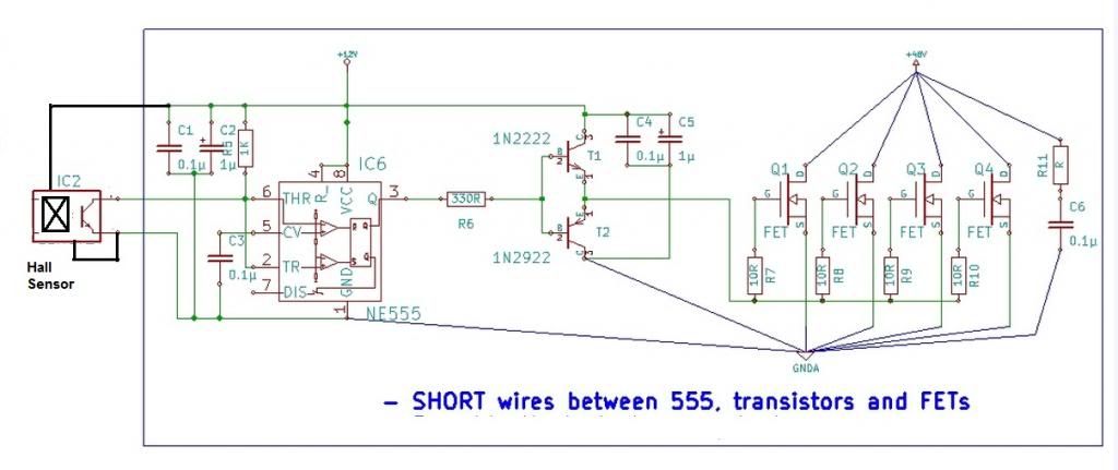
                                Hello Cornboy,

                                Here's JohnStone's circuit, modified for use with a hall-effect sensor. The vane's width dictates the duration of the pulse.


                                Alternatively, you can wire the LM555 as a monostable (fixed pulse width) and use the hall to trigger it at pin 2 of the 555. If you intend to go this route I can draw it up for you if needed.

                                Have fun!

                                Lester

                                Comment

                                Working...
                                X