Announcement

Collapse
No announcement yet.

My Motors got me to Tap into Radiant Energy

Collapse
X
 
  • Filter
  • Time
  • Show
Clear All
new posts

  • Great.

    Originally posted by Lester444 View Post
    Hello Cornboy,

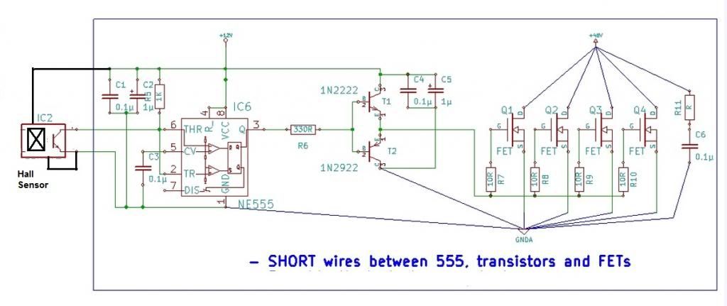
    Here's JohnStone's circuit, modified for use with a hall-effect sensor. The vane's width dictates the duration of the pulse.


    Alternatively, you can wire the LM555 as a monostable (fixed pulse width) and use the hall to trigger it at pin 2 of the 555. If you intend to go this route I can draw it up for you if needed.

    Have fun!

    Lester

    Thanks Lester, that would be great, i would like to control the time-on to the stators on MAG3-SB (scratch build) by altering the metal vane, something that is completely tangible for me.

    I think the hall sensor will be able to handle the required RPM, they are used in automotive for 6 and 8 cyl up to around 6000 RPM.

    Thanks Mate, Cornboy.
    Comment


    • Deeerrrr!

      Originally posted by Cornboy 555 View Post
      Thanks Lester, that would be great, i would like to control the time-on to the stators on MAG3-SB (scratch build) by altering the metal vane, something that is completely tangible for me.

      I think the hall sensor will be able to handle the required RPM, they are used in automotive for 6 and 8 cyl up to around 6000 RPM.

      Thanks Mate, Cornboy.


      Sorry Lester, i read your post too quickly, the circuit you show is what i need, red power in, black earth, and green output.
      Thanks, and if you think there is a way to make it any more bulletproof, as in seperate earth from mosfet's etc, please let me know.

      @ John Stone, and all, would it be an advantage to supply gates with 18V instead of 12V, for fast overcoming of capacitance and hard switching?.

      Thanks and regards Cornboy.

      Comment


      • Originally posted by Cornboy 555 View Post
        ..... and if you think there is a way to make it any more bulletproof, as in seperate earth from mosfet's etc, please let me know.
        Hello Cornboy,

        I have no idea what coil you are going to drive with this. If it goes directly to the motor you must consider that a motor's winding consisting of a few turns of wire is actually a DEAD SHORT-CIRCUIT until the rotor spins. Depending on your power supply's or battery's current capability you can easily blow a FET in the split-second after you apply power but before the rotor spins. That's the danger with letting the vane determine the pulse width.

        For the first trial I would go with a fixed-width pulse driver, just a few micro-seconds initially, to allow the rotor to accelerate from standstill. Then increase the pulse width for more rpm or load regulation. Give more details of your setup/motor so we can understand your application better. At this point the Arduino seems to be the best way to go although I'm not sure if there are still un-used ports to get the signal from a hall sensor.

        If I had 18v supply I would drive the FET from that.

        Lester

        Comment


        • @UFO:
          Thanks for mentioning that "old" coil diagram! My question is: Will we pulse the coil synchronously with commutator timing or will will we emit several pulses while commutator connected to brushes? Where will teh harvesting time(s) be exactly? I feel to have still lag of understanding ?
          @Qvision:
          IRFP460 is quite good for start. I own them too. 500V is quite rugged but please note that the RDSon is 0.27Ohm! As rule of thumb: @100°C we have 60% of amp and double RDSon. Infineon coolMOS have reuced RDSon by factor 3 minimum.
          For rugged design you should make use of absolute 80% of max. ratings at 100°C.
          Make yup your mind in what your setup requres and then decide on FETs. Unfortunately there is no general rule available.
          Please do first tests with car bulb (H7 / H4) in series to load in order to protect your setup.
          @Cornboy
          Any type of FET gets its minimim RDSon at a certain voltage (usually about 6...10V - see datasheet). There is no major advantage to go far above. 20V is usually abs. max.! The correct voltage needs to be negotiated. If the driver can drive plenty of current it is less critical. Consult my last schamtic for those rugged drivers from TI (UCC.....). For 555 it is not safe to go above 15...16V.
          Good do know: We need to protect the gate from higher voltages (20V). Those voltages are induced at gate if we switch off and get sharp spikes. This spits via an inherent cap in the FET back to the gate. If the driver can not handle it we need to add a protection to gate (see diodes inmy circuit)

          @ALL: PLease do not get confused by these disussions. I try to explain characteristics in order for you to be able to decide yourself.
          It is a big difference if you pulse little motors or 100Amps / 48V. It is like comparing a small RC car and a true racing car. Both own optimized technologies and they seem to be similar - but they are not..
          For small applications those 555 circuits are quite good. But do not expect to drive the imperial motor with them. After uncountable mishaps you will head to the "racing" driver finally.
          So please let's categorize your application before discussing:
          555 grade or racing grade with true monster drivers. Cornboy: For what app. do you head to?

          @ Lester:
          1. I ask if it would be advisable to introduce a current sensor in order to protect the drivers. At max. current adjusted the driver will switch off up to the next trigger.
          2. If we apply higher gate voltage we can switch on faster but NOT OFF. The FET does not care if it dies because of overheating from switch on or off.

          @ALL:
          I have not all components available for the last circuit I posted but I will compose a demo with similar casings in order to demonstrate what the last circuit will look like (SHORT wiring). It will be once again a 3D wiring but now living on a CPU cooler.
          JohnS
          Experts spend hours a day in order to question their doing while others stopped thinking feeling they were professionals.

          Comment


          • @ John Stone

            Thanks very much for the info JS


            All the best,

            Comment


            • Didn't get much reading done yesterday, i hope to finish the thread today !


              Cheers,

              Comment


              • Cornfused.

                Originally posted by Lester444 View Post
                Hello Cornboy,

                I have no idea what coil you are going to drive with this. If it goes directly to the motor you must consider that a motor's winding consisting of a few turns of wire is actually a DEAD SHORT-CIRCUIT until the rotor spins. Depending on your power supply's or battery's current capability you can easily blow a FET in the split-second after you apply power but before the rotor spins. That's the danger with letting the vane determine the pulse width.

                For the first trial I would go with a fixed-width pulse driver, just a few micro-seconds initially, to allow the rotor to accelerate from standstill. Then increase the pulse width for more rpm or load regulation. Give more details of your setup/motor so we can understand your application better. At this point the Arduino seems to be the best way to go although I'm not sure if there are still un-used ports to get the signal from a hall sensor.

                If I had 18v supply I would drive the FET from that.

                Lester


                Sorry Lester, my application is a scratch build of UFO's Magnificence of 3 6 9 posted on motor thread.
                36 pole, 3 input brushes, 3 output brushes, on both ends, 6 stators.

                Since my main interest is in EV propulsion in am starting with a prototype build of a motor i am hoping will be approx 15 - 30 HP.
                Rotor is 190mm dia and 200mm long, and stators will be wound coils, not PM's,so it can be scalable to larger sizes.

                In order to achieve radiant output from stator coils, they will be pulsed, but at first the pulsing will be shaft timed for the coils ON time. The design i am using for stator coils-cores will also allow for secondary coils at a later stage.

                Also to start with the rotor coils will be commutator driven.

                Later i will take the plunge of pulsing both rotor and stator in parrallel, but for now, eventhough UFO has explained it to me, i am still trying to fully understand how possible multiple pulses per commutator segment on time would effect performance.

                Soooo, the electronics i will need will have to be at least as robust as what JS has posted for Imperial or heavier.

                As i am waiting on laminations to arrive, i can't give you any coil spec's but i will try to stay above 1.5 ohm on rotor coils and probably about a total of 9 ohms on stator coils when series connected.

                Hope this makes my application more clear to you Lester.

                Once again sorry for any confusion.

                Warm Regards Cornboy.

                Comment


                • Originally posted by JohnStone View Post
                  @ Lester:
                  1. I ask if it would be advisable to introduce a current sensor in order to protect the drivers. At max. current adjusted the driver will switch off up to the next trigger.
                  Hello John,

                  Looks like we are going into hyper-drive now: High-power / high-energy circuits. We should approach with caution!

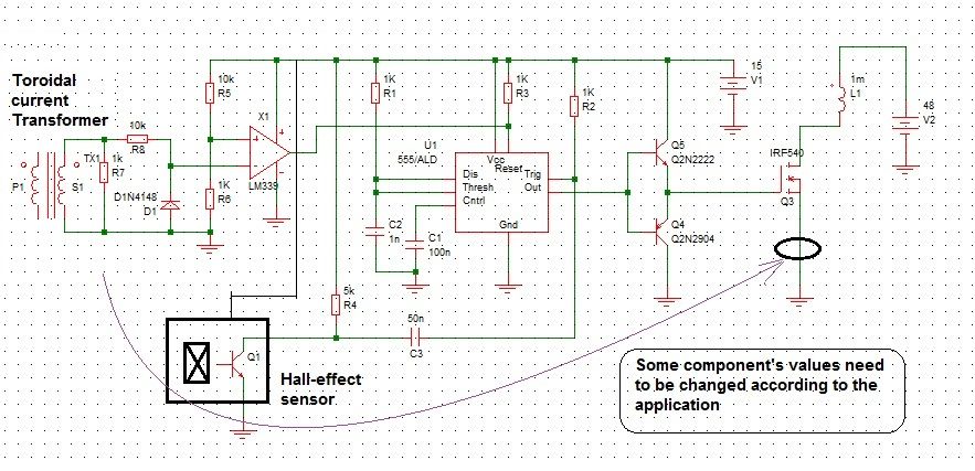
                  That's a great idea you mentioned above. I'm not sure if the Arduino will be fast enough (SW is slow) so I am suggesting a hardware implementation
                  of the current sensor. This is one possible way to do it: (Resistors waste too much power)

                  A small toroid is wound with multiple turns for the secondary, and the primary is a single large wire that goes through the center of the toroid.
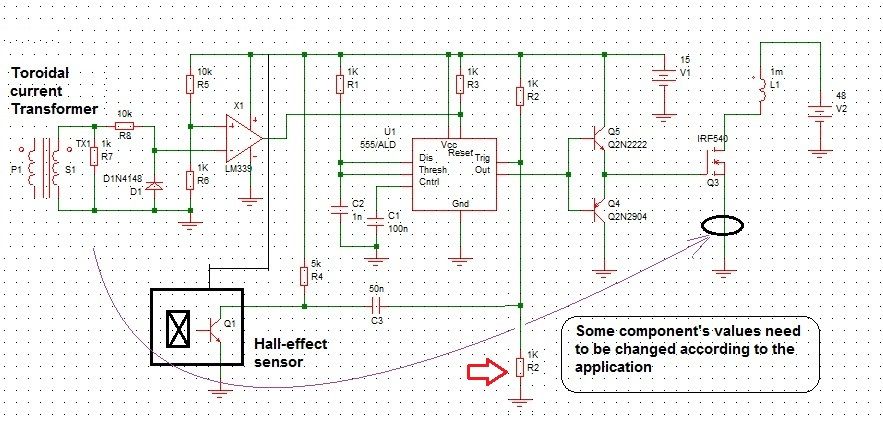
                  This is a current transformer (like a clamp meter ) and it "senses" the current going through the single wire in the center of the toroid. The current (yes current) coming out of the toroid's secondary is fed across a resistor (turns-ratio & resistance determines Vout) and the resulting voltage drop across the resistor is fed to a comparator to compare vs a pre-set voltage. The comparator's output may then be fed to the reset pin of the LM555 so that once the preset current is exceeded the pulse duration is cut short (FET drive is turned off). I have drawn the circuit to show you what I mean.


                  Originally posted by JohnStone View Post
                  2. If we apply higher gate voltage we can switch on faster but NOT OFF. The FET does not care if it dies because of overheating from switch on or off.
                  As always there are tradeoffs. A higher gate drive voltage results in lower RDSon (good, cool FET), but then the signal will have to slew through
                  a wider voltage (18v for example) and that's additional time required for turn-off (bad?) as compared to 12v. The delta of 6v (18v-12v = 6v) can result in 50% more turn-off time relative to 12v (18v/12v = 150%). That may look bad but it may not necessarily be true, because now the di/dt of the coil is slower also, and that results in a lower spike voltage, perhaps hundreds of volts instead of thousands of volts. No snubbers at all, but provide a path where the stored energy in the coil can go to AT ALL TIMES.

                  But if you're trying to make a spark (as in an automotive ignition coil) the fastest turn-off time for the FET is definitely the way to go.

                  Lester

                  Comment


                  • The Fog will lift.

                    Originally posted by JohnStone View Post
                    @UFO:
                    Thanks for mentioning that "old" coil diagram! My question is: Will we pulse the coil synchronously with commutator timing or will will we emit several pulses while commutator connected to brushes? Where will teh harvesting time(s) be exactly? I feel to have still lag of understanding ?
                    @Qvision:
                    IRFP460 is quite good for start. I own them too. 500V is quite rugged but please note that the RDSon is 0.27Ohm! As rule of thumb: @100°C we have 60% of amp and double RDSon. Infineon coolMOS have reuced RDSon by factor 3 minimum.
                    For rugged design you should make use of absolute 80% of max. ratings at 100°C.
                    Make yup your mind in what your setup requres and then decide on FETs. Unfortunately there is no general rule available.
                    Please do first tests with car bulb (H7 / H4) in series to load in order to protect your setup.
                    @Cornboy
                    Any type of FET gets its minimim RDSon at a certain voltage (usually about 6...10V - see datasheet). There is no major advantage to go far above. 20V is usually abs. max.! The correct voltage needs to be negotiated. If the driver can drive plenty of current it is less critical. Consult my last schamtic for those rugged drivers from TI (UCC.....). For 555 it is not safe to go above 15...16V.
                    Good do know: We need to protect the gate from higher voltages (20V). Those voltages are induced at gate if we switch off and get sharp spikes. This spits via an inherent cap in the FET back to the gate. If the driver can not handle it we need to add a protection to gate (see diodes inmy circuit)

                    @ALL: PLease do not get confused by these disussions. I try to explain characteristics in order for you to be able to decide yourself.
                    It is a big difference if you pulse little motors or 100Amps / 48V. It is like comparing a small RC car and a true racing car. Both own optimized technologies and they seem to be similar - but they are not..
                    For small applications those 555 circuits are quite good. But do not expect to drive the imperial motor with them. After uncountable mishaps you will head to the "racing" driver finally.
                    So please let's categorize your application before discussing:
                    555 grade or racing grade with true monster drivers. Cornboy: For what app. do you head to?

                    @ Lester:
                    1. I ask if it would be advisable to introduce a current sensor in order to protect the drivers. At max. current adjusted the driver will switch off up to the next trigger.
                    2. If we apply higher gate voltage we can switch on faster but NOT OFF. The FET does not care if it dies because of overheating from switch on or off.

                    @ALL:
                    I have not all components available for the last circuit I posted but I will compose a demo with similar casings in order to demonstrate what the last circuit will look like (SHORT wiring). It will be once again a 3D wiring but now living on a CPU cooler.
                    JohnS


                    Thanks for all your great info on FET's John, i am beginning to see the picture now. It appears that 12V is sufficent as long as there is plenty of current from the driver. Also ultrafast switch off is very important for max Radiant out.

                    I can't find the UCC drivers here in OZ but have located some 12A drivers and will post specs for drivers and FET's for your advice and guidance if you would be so kind. Also would the FOD's be good opto's for your latest circuit posted? and how would you connect a vane hall sensor to them?

                    I too still have a lag of understanding of your question to UFO.

                    I visualise that multiple pulses to a rotating rotor coil, per commutator segment on time, would create a negative force to rotor until rotor came up to speed of pulses, but of course that is from my very limited understanding of what really happens.

                    I'm sure UFO will clear the fog on this for us.

                    Warm Regards John Stone.

                    Comment


                    • Hello Cornboy,

                      That's a HUGE motor you're making!!! Lotsa amps so you definitely need some protection for the FETs.

                      The last circuit I posted is for sensing an over-current condition, or, some other preset current not necessarily an overload condition. I am thinking this would be good for your application but let's wait for JohnStone's comments.

                      I like they way you think BIG!!!

                      Lester

                      Comment


                      • Sorry but I need to correct my diagram. Please add the 1k resistor shown (red arrow). THIS CIRCUIT DIAGRAM IS NOT FINAL.

                        Thanks,

                        Lester

                        Comment


                        • I decided i couldn't wait for my stuff to arrive from China so i went with what i had.

                          1. DC PSU, 18V @ 2A.
                          2. A decent PWM (rmcybernetics OCX).
                          3. A 4ohm coil of 0.5mm wire.
                          4. Two 1N4001 diodes.
                          5. A small neon bulb.

                          So no need for making a PWM, no need for voltage regulators or transistors.

                          And guess what ? Purple-white plasma in the neon bulb !

                          I see this occasionally in my SSG cicuit. I know very little about electronics/energy etc ... i've only been experimenting for 2 years or so and last year i was almost completely inactive ...

                          How do i know if this is cold electricity ? What tests can i do ?

                          Should i put a resistor at the output instead of a neon, or will that turn it into hot electricity ?

                          How can i know for sure ?


                          All the best,

                          nibs.

                          Comment


                          • Well, that was easily answered - the neon bulb got hotter and hotter ...

                            Anyway, here's a pic :


                            So has anyone done power out measurements on a scope ?

                            How do we know the difference between plasma and RE ?

                            I have ordered a cheap USB scope that only goes up to 8KHZ (it's all i need right now) but surely someone in this thread has a decent scope and can take some power measurements ?


                            All the best,

                            Comment


                            • Did a quick video, plasma occurs after 1:27 :

                              Simple version of UFOPolitics' cold-electricity coil. - YouTube


                              All the best,

                              Comment


                              • Originally posted by Lester444 View Post
                                Sorry but I need to correct my diagram. Please add the 1k resistor shown (red arrow). THIS CIRCUIT DIAGRAM IS NOT FINAL.
                                ...
                                This is basically an AC transducer. It will transfer at edges only.

                                DC transducers work with hall sensors inserted in to the ring ferrite. Manufacturers LEM

                                In fact we do not need true measuring but an overload protection only.

                                I remember to have built a burgler alarm for my car. I measured the voltage drop via + line when the internal light switched on - and it worked well. So we do not need a shunt but a short piece of copper wire. The main concern will be to prevent noise from HER.

                                Alternatives possible (current technology):
                                Allegro produces hall current sensors for DC up to +- 30A and galvanically separated.
                                Purchase breakout board here It is a Pololu open source breakout board. $9 is quite intriguing!

                                Extension for amp range by adding a piece of coppr wire as shunt The internal "wire" is copper as well. (less accuracy!)

                                I need to ponder on it but take this as thought food for now.

                                JohnS
                                Last edited by JohnStone; 01-14-2013, 04:12 PM.
                                Experts spend hours a day in order to question their doing while others stopped thinking feeling they were professionals.

                                Comment

                                Working...
                                X