Announcement

Collapse
No announcement yet.

My Motors got me to Tap into Radiant Energy

Collapse
X
 
  • Filter
  • Time
  • Show
Clear All
new posts

  • @Lester, Cornboy
    Regarding gate voltage:
    i.e. IRFP460
    Data sheet: 0.27Ohm at VGS 10V and 10A
    The FET is rated for 20A permanent or 80A pulsed DC current.
    ----------------------
    The 10V VGS will be suffitient for 60A (0.75Ohm). Above RDSon will increase considerabyl (2.0 Ohm at 80A) up to thermal FET death.
    Increasing VGS above 10V will help in the range 60A ..80A to keep the RDSon below 0.75Ohm
    -------------------------
    Conclusion:
    Higher VGS then specified in datasheet:
    • will reduce RDSON in highest amp range only and wil not add any contributin in normal 80% load.
    • will contribute a small delay at switch off but not reduce speed of switch off
    • will reduce switch on a bit IF and only IF the driver can source several amps
    • once again keep in mind that ABSOLUTE MAXIMUM RATINGSS do not get rue all at same time. i.e. RDSon is valid for 25°C and will increase with temperature and amps


    @ALL: I do not feel comfortable to pollute this thread being dedicated to pulsed coils. I am afrait most of you do not really know on stuff I talk above exactly in this post. We might need to find a solution for this.

    @qvision!
    Amazing you got this result within short time! These effects are a building stone to be added to UFOs asymmetric motors. In the past one of the members (can't remember who) drove a motor out of this energy and proved to not increase input power.
    Nobody can measure the power out of radiant because our meters regard losses in order to interpret them as measurement. And radiant behaves very different. We have no meters for it just now.
    Radiant is an effect of switched electrical power. Current science does not regard for it at all except protecting all sorts of electrical equipment from surge and other apparently malicious effects.
    The high art is getting this energy interacting with matter in order to use it. You performed UFOs experiment successfully getting HER to interact with matter (neon). This experiment was an introductional tutorial in order make us grasp what stuff his motors make use of.
    Thanks for taking the effort in order to read the whole thread! Hat up!
    JohnS
    Last edited by JohnStone; 01-14-2013, 04:10 PM.
    Experts spend hours a day in order to question their doing while others stopped thinking feeling they were professionals.

    Comment


    • Hello QVision

      Originally posted by qvision View Post
      Did a quick video, plasma occurs after 1:27 :

      Simple version of UFOPolitics' cold-electricity coil. - YouTube


      All the best,
      Hello QVision,

      That's fine, excellent testing!, however I do not see on video a very well defined Time Off (Neon Completely Off)...at any point on video.

      Basically the Orange Light is your Hot flow...and it is clear that it is steadily On...Now you kept forcing it at Higher Pulses and that triggered the Radiant in...but both currents were fully on, so it was a mix of Purple-Orange Light...and of course your Neon will get very hot.

      Watch My Neon here:

      RADIANT ENERGIZED NEON - YouTube

      And you could pause it and note it gets completely turned off at times of primary start switching pulses...that is the idea.

      Now, Your Diodes may not be filtering right and enough the Hot...but mainly, I do not see well defined Off Times there...It must Flicker, On-Off.

      But You DO are getting there my friend!...so, keep at it and you will see HER much cleaner, brighter and with almost no Hot on...


      Regards


      Ufopolitics
      Last edited by Ufopolitics; 01-14-2013, 04:17 PM.
      Principles for the Development of a Complete Mind: Study the science of art. Study the art of science. Develop your senses- especially learn how to see. Realize that everything connects to everything else.― Leonardo da Vinci

      Comment


      • Blew the neon, and it's my last one

        No results at all with a 23W CFL.


        All the best,

        Comment


        • Originally posted by Ufopolitics View Post
          Hello QVision,

          That's fine, excellent testing!, however I do not see on video a very well defined Time Off (Neon Completely Off)...at any point on video.

          Basically the Orange Light is your Hot flow...and it is clear that it is steadily On...Now you kept forcing it at Higher Pulses and that triggered the Radiant in...but both currents were fully on, so it was a mix of Purple-Orange Light...and of course your Neon will get very hot.

          Watch My Neon here:

          RADIANT ENERGIZED NEON - YouTube

          And you could pause it and note it gets completely turned off at times of primary start switching pulses...that is the idea.

          Now, Your Diodes may not be filtering right and enough the Hot...but mainly, I do not see well defined Off Times there...It must Flicker, On-Off.

          But You DO are getting there my friend!...so, keep at it and you will see HER much cleaner, brighter and with almost no Hot on...


          Regards


          Ufopolitics
          Thanks UFO

          Yes, i will wait until the proper diodes etc arrive and do more testing.

          I wasthinking of buying 3 x 12v SLA's but if i spend twice the money i can get a 30V/5A DC PSU, something i want to get anyway, so i will purchase one of those in time.

          I am enjoying this very much and it is certainly intriguing, thanks for your time and patience with us all


          All the best,

          Comment


          • Originally posted by JohnStone View Post
            @UFO:
            Thanks for mentioning that "old" coil diagram! My question is: Will we pulse the coil synchronously with commutator timing or will will we emit several pulses while commutator connected to brushes? Where will teh harvesting time(s) be exactly? I feel to have still lag of understanding ?

            JohnS
            Hello My Dear Friend,

            When I originally started this Thread...I already had this Motors built and running...and I was getting Radiant out from their Negative Generator side, it was a different current than we are used to...but I got HER very "mixed up" with Hot...After I did several testing, I realized at low pulses to motors...where their shafts were barely going a quarter Turn per minute...(almost like a Servo Motor)...then I saw HER stronger...

            I added Diodes to the Generator Output...and still saw HER in even more Radiant stages...it was very weird that Diodes were blocking the "Real Hot" according to Meters reading...and I still got HER out...

            It was then when I took Motors apart and made Stationary Coils, following same circuit I had...but, not Motoring or Rotation there...I was fascinated by this Phenomena...then "forgot" completely about Motors and started here...with electronics, pulsing and Stationary Coils...

            The Thing is...We do not need a Stationary Coil...We have as many as our Motors have inside their Rotors...or in their Stators...Why build a separate Coil?...if we could use the ones are at work as also utilize their magnetic fields swapping to pro-pulse our motors?

            The Problem is that once rotor gains speed...the Off Times become shorter at Commutator, therefore, Radiant flickers very dim...but once we set a Mechanical load to Motor...she grows very brightly out...due to RPM's decrease, increases the Off Times, but at very High Charges of Coils (High Peak Voltage Pulses)....then We get those very High Spikes that would even arc against the Brush Brass Housings in our Imperial Motor.

            That is why I brought in yesterday that Old Diagram...

            Now, the big difference we all must picture here...is that in an Asymmetrical Motor, we have Dynamic Coils, instead of Static...they are moving related to Time and Space, but it is exactly the same thing though.

            For example, in Imperial set up,(or it could apply to any other set I have displayed here) we Pulse/Energize/Charge P1 for a fraction of Time, and that creates an automatic Turn Off/Disconnect from Feed...a "Time Off" that travels free until it meets the second nearest Gate (P8 Port in this case)...and there it delivers its Time Off reversed Charges, However, it does it from both feed sides, positive and negative, not like when we were pulsing it steady...with a Positive Source always On...It was then when I came up with the Anti-phase Positive-Negative Drains Pulsed Controller Design...THEN We were pulsing/reproducing exactly the way Motors do it...

            Now, going back to Imperial...We have to "see/picture" the Dynamic Coils there following an Endless Spiral Cycle...a sequence of Times On-Times Off, that jumps to next terminal to deliver the "other half" of the Cycle...and if we feed P1 and P15 (180º apart), then we will be picking up their Off Times at Gates P8 and P22 respectively (Note I am referring to Gates, not Pairs of Coils, for reference related to Main Diagram...we have named those ports/terminals as P1, P8, P15 and P22 at the Four Quadrant..even though they are interacting with ALL Coils in the Machine)

            If We feed Linear this Motors, and do not "Route/Exit" their "Exhaust Side"...they will be creating an Overflow within the Armature, where In-Out Flow will be colliding with each others, raising the Amperage at Armature/Rotor AND therefore Terminals/Cables.
            We do it even more...IF We feed IN, like I did, ALL Terminals Input (P1,P8,P15,P22)...the Collision is then Galore.

            So what do we do?

            Simple...We go back to that Old Diagram...kind of a Reversed Engineering to our own System...

            I will be showing a Diagram about this at the other Thread...since it is directly related to Motor Commutation Works.


            Regards


            Ufopolitics
            Principles for the Development of a Complete Mind: Study the science of art. Study the art of science. Develop your senses- especially learn how to see. Realize that everything connects to everything else.― Leonardo da Vinci

            Comment


            • Thanks Ufo for teaching!
              Some facts clreared up on others I continue to ponder!
              JohnS
              Experts spend hours a day in order to question their doing while others stopped thinking feeling they were professionals.

              Comment


              • I promized to build a sample for demonstrating driver PCB - SHORT wired - my style. But please note: it is a sample for crafting. The devices are different from true circuit but same shape out of my scrap box. Some wires and descrete components missing.


                The driver bord top side view. You see there the drain as pin still unconnected but prepared for a bus bar. The devices soldered there symbolize the FET driver 9A, opto and 74c14 as signal shaper.

                The driver bord top side view. Connections for gate / driver and source performed SHORT and MASSIVE more than any PCB can do for you. (sorry for not removing filing dust)

                The blocking caps are of ceramic type and stacking is possible (left one - can't be seen well). The big one is 10µ 16V!!
                Hint: Any cap has a certain resonant frequency where it does not perform as cap. It depends mainly on shape and material. Therefore it is advisable to add different capacitors and shapes in order to get a blocking feature over the entire frequency range. The caps need to deliver up to 9A for short time of several ns. Forget it if you have leaded ones with long pins.
                Please note: driving FETs is high current, high frequency. The only drawback missing is heat! Voltage drop, inductance ..... all apply here. Therefore SHORT MASSIVE connections.


                Heat sink from an old Pentium PC recycled with driver being mounted. I added a threaded hole for mounting.


                Another hint is to use bus bars out of copper for connecting source and drain if using multiple FETS for one channel. They are readily available at installers. They use them in order to connect the input of fuses at electric home installation. You see here some single bars and one as triple stack for three phase installaton. I hope this is not a local European phenomenon but you can get them all over the world.

                This is the stuff momnster driver are built of. You decide on hat big or little monster you intedn to build. I hope I could add some understanding and help for further quality replications.

                BTW. The pics were taken with an old Olympus 100RS. Original 1.4 Mpixel and shrunk to VGA format. They are still very clear. This indicates that good lenses are essential and not the Mpixel hype thy tell us to be essential.
                JohnS
                Last edited by JohnStone; 01-14-2013, 09:07 PM.
                Experts spend hours a day in order to question their doing while others stopped thinking feeling they were professionals.

                Comment


                • Thank you UFO and John

                  Thanks UFO, it's great to hear your voyage of discovery

                  JS, what you are doing looks great, it's just way over my head at the moment, but i'm still learning

                  A member of another forum pointed out something from a book called From The Archives of Lester J. Hendershot, here is a screenshot :


                  Interesting, eh ?

                  I also like the fact that it seems the magnetic field of a permanent magnet seems to be in constant natural rotation.

                  Normal speed :

                  JK Plasma Magnetics Experiment 2 - YouTube

                  Slow motion :

                  JK Plasma Magnetics High-Speed Video - YouTube

                  Food for thought ...


                  All the best,

                  Comment


                  • Originally posted by JohnStone View Post
                    This is basically an AC transducer. It will transfer at edges only.
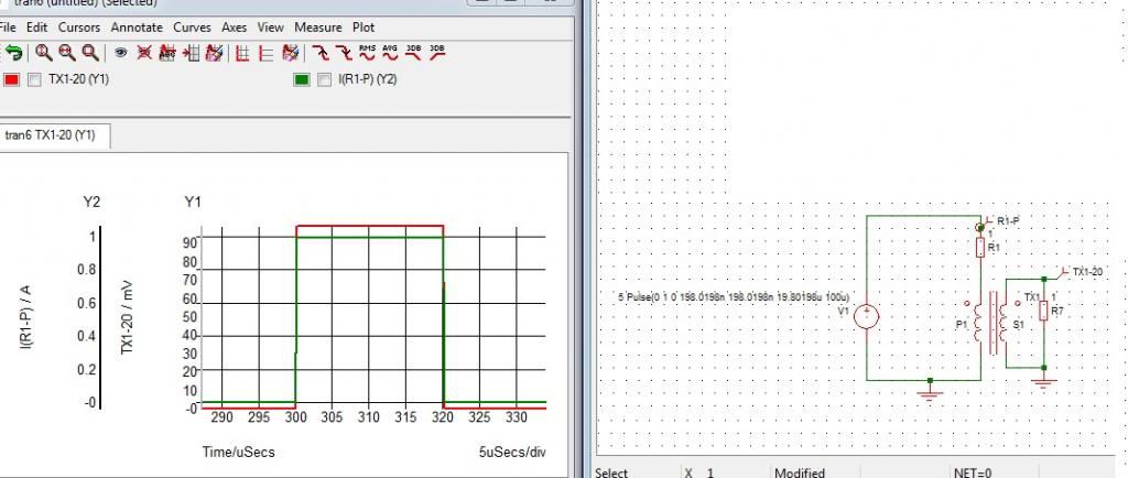
                    Sorry Johnstone but I have to disagree with you. If you open up a SMPS you will find that some brands/models use this EXACT SAME method that I described with the toroid. What is your switching frequency anyway? A transformer will put out square-shaped pulses also (not just the edges as you said), if that's how your current waveform looks like. So not only the edges but also the top, IF YOUR FREQUENCY IS HIGH ENOUGH. Look at the CURRENT waveform on the graph below. The CURRENT is converted to VOLTAGE using the resistor at the secondary. I thought you knew how its done.

                    Anyway, if your switching frequency is low then I agree, the toroid concept won't work. You can take out the toroid and substitute a shunt in its place and you now have your overload protection. Same circuit as shown. You can make a shunt using a brass rod used for brazing. I have used 3mm brass rod as a shunt in a 40A application, with separate force & sense connections. Caution: the resistance will change with temperature and so the voltage drop will also change.

                    Regards,

                    Lester

                    Comment


                    • Hmmmm.

                      Hello John, Lester ,All, could this be a good unit to drive motor coils?

                      Thanks Cornboy.
                      Attached Files

                      Comment


                      • @Cornboy: Your link seesm to be corrupt.

                        @qvision: Yes rotating magentic vortex. Download the booklet: "The secret world of magnets" from Howard Johnson"

                        @Lester:
                        My understeanding differs: As long we talk of linear range of core:
                        Constant voltage to a coil -> linear increase of primary current (probe it) -> conversion to secondary as image of the slope dI/dT of current and not the absolute current. If it were an image of absolute current we should have an increasing slope. The core will not transfer anything if current settels to a excessive high and stable DC current.

                        Yes a shunt can be measured. At higher temperature it increases its resistance. That's fine because at higher temperature FETs degrade their max. current.
                        The Allegro component makes use of a copper "shunt" as well but it is being checked in terms of hall effect. Advantage: galvanically separated.
                        Anyway: current measurement is a matter of further enahncements.
                        Experts spend hours a day in order to question their doing while others stopped thinking feeling they were professionals.

                        Comment


                        • Hi all,

                          Some time ago I was testing with this coil.

                          It is made with cat5 cable (network-4 twisted pairs).

                          I used 82 meters.
                          170mm outside, 52mm inside and 66mm in height.


                          Regards
                          http://Cacharreo.com.es/foro

                          Comment


                          • off time

                            Hello UFO i dont understand why the neon has any OFF TIME. Is it because we are pulsing the coil intermittently or is the neon intermittent or is SHE undecided? Thanks Al Sollid

                            Comment


                            • Originally posted by asollid View Post
                              Hello UFO i dont understand why the neon has any OFF TIME. Is it because we are pulsing the coil intermittently or is the neon intermittent or is SHE undecided? Thanks Al Sollid
                              Hello Asollid,

                              The Set Up is at follows...

                              We Pulse Coil On Off on the Hot Side...Diodes send to Neon from Coil the opposed On Off Pulses...Neon Goes turns Off at our On Times from Hot...Neon Turns On (Purple) at our Off Times at Hot (our Oscillator).

                              Watch this video closely...

                              Ultraviolet-Green Effect at Start of Oscillations - YouTube

                              Camera shutter is too slow to Capture real time interactions of Radiant Field...that is why, I am running video at very slow motion...

                              Note how within the Oscillating Wave at Scope, there is another one growing from low to high...and when it reaches top...Light turns On Green or Purple...till it reaches full peak at both Channels then it becomes pure white...

                              Now, a Neon will never become pure white like a CFL...it will be either Orange or Purple, or both...so, when we are doing it right...at very low pulses...we will see mostly Purple Light...flickering, wobbling its plasma ball along electrodes...like in the video I have shown previously "Radiant Neon"...

                              Hope this helped you.


                              Regards


                              Ufopolitics
                              Last edited by Ufopolitics; 01-15-2013, 06:34 PM.
                              Principles for the Development of a Complete Mind: Study the science of art. Study the art of science. Develop your senses- especially learn how to see. Realize that everything connects to everything else.― Leonardo da Vinci

                              Comment


                              • Maybe my bad.

                                Originally posted by JohnStone View Post
                                @Cornboy: Your link seesm to be corrupt.

                                @qvision: Yes rotating magentic vortex. Download the booklet: "The secret world of magnets" from Howard Johnson"

                                @Lester:
                                My understeanding differs: As long we talk of linear range of core:
                                Constant voltage to a coil -> linear increase of primary current (probe it) -> conversion to secondary as image of the slope dI/dT of current and not the absolute current. If it were an image of absolute current we should have an increasing slope. The core will not transfer anything if current settels to a excessive high and stable DC current.

                                Yes a shunt can be measured. At higher temperature it increases its resistance. That's fine because at higher temperature FETs degrade their max. current.
                                The Allegro component makes use of a copper "shunt" as well but it is being checked in terms of hall effect. Advantage: galvanically separated.
                                Anyway: current measurement is a matter of further enahncements.

                                Hello John, when i click on the link it comes up as a full PDF of the component, so i don't know watts up.
                                Maybe someone else can try and let me know.

                                I was just amazed that i could post it, never done it before so maybe i did something wrong!.

                                Regards Cornboy.

                                Comment

                                Working...
                                X