Announcement

Collapse
No announcement yet.

My Motors got me to Tap into Radiant Energy

Collapse
X
 
  • Filter
  • Time
  • Show
Clear All
new posts

  • Originally posted by prochiro View Post
    @JohnStone
    A lot of discussion has been done about fets and although I understand the basics of operation and circuit development, I still am in a quandary about which fet to use. I am talking about the Imperial motor being run with a capable, solid fet, which will do the job. Cost at this point is not as important as will it do the job although 430.00 dollars is not what I am thinking about. If you know of a fet in the mid range of cost like this, that will do the job, what might that fet be? Also, is there a way , other than adding one at a time, to know about how many fets it will take, as a rough guide? I am trying to set up one large board for this and this information would help to picture in my mind where I am going. Sorry for the stupid questions in advance.
    Dana
    @Dana

    I had the same question. I found and have just ordered a few of Infineon Power MOSFETs. I believe these came out last Nov.
    Part ID: IPW65R037C6
    Info: 650 volts, Ohms 0.037, Amps Pulsed=297A @25 83A @100 52A, Gate threshold 3 volts, timing 22ns 32ns 140ns 7ns.

    Pull up the Spec. and find out what the values above mean. I ordered mine from Arrow Electronics at a cost of $13+

    Good luck, have a nice day.

    Comment


    • Infineon Technologies SPW52N50C3 MOSFET COOL MOS N-CH 560V 52A

      Hello John Stone, this might be interesting source for the
      Infineon Technologies SPW52N50C3 MOSFET COOL MOS N-CH

      Price: (US)
      1: @ $11.84
      10: @ $9.71

      SPW52N50C3 Infineon Technologies | Mouser

      Thanks for all the suggestions.


      Warmest regards

      light

      Comment


      • Can't find price yet!

        Originally posted by prochiro View Post
        @JohnStone
        A lot of discussion has been done about fets and although I understand the basics of operation and circuit development, I still am in a quandary about which fet to use. I am talking about the Imperial motor being run with a capable, solid fet, which will do the job. Cost at this point is not as important as will it do the job although 430.00 dollars is not what I am thinking about. If you know of a fet in the mid range of cost like this, that will do the job, what might that fet be? Also, is there a way , other than adding one at a time, to know about how many fets it will take, as a rough guide? I am trying to set up one large board for this and this information would help to picture in my mind where I am going. Sorry for the stupid questions in advance.
        Dana

        Hello DANA, JS, all, International Rectifier just released a new industrial quality 300v Mosfet, will try to attach.

        Regards Cornboy.
        Attached Files

        Comment


        • Originally posted by Cornboy 555 View Post
          Hello DANA, JS, all, International Rectifier just released a new industrial quality 300v Mosfet, will try to attach.

          Regards Cornboy.
          Fast, low RDS=N, high amp
          But 300V is too low in order to pulse motors seriously (my feeling).
          • We are not encouraged to add protection devices in order to not make HER angry. In fact we can tune the switching speed by increasing the gate resistor.
          • We are ecouraged to switch fast in order to attract HER.
          • Voltage spikes are determined by energy stored (current and inductivity like flywheel with mass and rpm) AND the switching speed (flywheel -> decellaration.

          For comparison:
          A normal ignition coil loads the points at primary side with up to 300V. It would do it even if there were no secondary winding because it is the reaction from inductivity at about 3A only. Depending on motor type the voltage spikes will be similar or worse.

          This FET might survive because in reality they are rated above but I would not use it for my pulser. Any similar normal FET with 550V would double its RDSon (= heat) and perform slower. Heat and amps increase RDSON additionally.
          Infineon coolMOS is in so far unique in performace - excecpt SiC from CREE of course (single transistor $50).

          Please accept: this is my humble opinion only. Anybody is free using the components of his choice and I would be happy to be proved being erroneous!
          JohnS
          Experts spend hours a day in order to question their doing while others stopped thinking feeling they were professionals.

          Comment


          • @IanKoglin

            Thank you VERY much, what a handy site

            @Lightworker1

            Thanks Lightworker1, but it was the replication by Sanskara316, mentioned in chapter two of Patrick Kelly's (free) free energy book :

            http://www.free-energy-info.co.uk/Chapter2.pdf

            This post here :

            http://www.energeticforum.com/renewa...tml#post203744


            All the best,
            Last edited by qvision; 01-17-2013, 11:00 PM. Reason: ADD.

            Comment


            • Originally posted by JohnStone View Post
              OH Sorry,
              1N... are diodes of course. 2N2222 and 2N2907 are the transitors I referred to.
              They are rated at about 0.8A current as maximum.
              The transistors you suggested might do well. Give them a try. No heat sink required.
              I hope you have a scope available in order to verify correct function.


              BTW: where do you get your second commutator? I have a smaller motor out of this family but the shaft is 2 mm less diameter at front side. Back side is identical.


              You are ecouraged to ask more questions! I want you as well to get your new pulser running well.
              JohnS
              G'Day John Stone
              Thanks for your help and especially for the quick reply

              I asked the supplier of the 1000w motor to get me an extra commutator and motor end complete with the brush board and brushes
              He Emailed me back and told me to buy these Items are dearer than to buy the complete motor
              I placed an order for a new motor and they wont be available for 6 to 8 weeks
              In the mean time I will build the controller
              Thanks again Kindest regards


              Always waiting for parts

              Comment


              • Thanks.

                Originally posted by JohnStone View Post
                Fast, low RDS=N, high amp
                But 300V is too low in order to pulse motors seriously (my feeling).
                • We are not encouraged to add protection devices in order to not make HER angry. In fact we can tune the switching speed by increasing the gate resistor.
                • We are ecouraged to switch fast in order to attract HER.
                • Voltage spikes are determined by energy stored (current and inductivity like flywheel with mass and rpm) AND the switching speed (flywheel -> decellaration.

                For comparison:
                A normal ignition coil loads the points at primary side with up to 300V. It would do it even if there were no secondary winding because it is the reaction from inductivity at about 3A only. Depending on motor type the voltage spikes will be similar or worse.

                This FET might survive because in reality they are rated above but I would not use it for my pulser. Any similar normal FET with 550V would double its RDSon (= heat) and perform slower. Heat and amps increase RDSON additionally.
                Infineon coolMOS is in so far unique in performace - excecpt SiC from CREE of course (single transistor $50).

                Please accept: this is my humble opinion only. Anybody is free using the components of his choice and I would be happy to be proved being erroneous!
                JohnS


                Good advice John, as usual, thanks very much.

                Regards Cornboy.

                Comment


                • Originally posted by JohnStone View Post
                  Ufo requested for his current setup a four phase oscillator.
                  Post
                  Post
                  I threw some components into the circuit and ask for discussion. It is what I intend to build.

                  The reason for using a microprocessor is because the circuit with logic ICs is lots of wires to draw and one use only. A micro is much more precise and versatile to use.
                  @Lester: Some suggestions for i.e. snubber circuit? Suggestions for additional protection?
                  @Nico: Arduino connected correct? What about modified program? Where did you connect your POT / LCD exactly?

                  TBD:
                  • 555 NMOS (slow but 200mA source sink at output) or CMOS (fast but 8mA only) - needs to be tested
                  • Control for dead time and frequency: Pot, digital pot or by simple terminal program from PC (USB)
                  • Display required?
                  • Option for current measurements required?
                  • Use of reset at pin at 555 in order to prevent unintended firing of FETs while program downloed and aother actions.


                  With some additions (voltge feedback) this circuit can peform as SMPSU - not high end precision PSU but suffitient in order to control the voltage for our loads from battery stack or welder. It depens on your requirements and your setup.

                  JohnS
                  G'Day John Stone
                  I really appreciate your help

                  In the above circuit You show that 5v going into the opto's on into the NE555 Chip Then 12v is picked up by the NE555 via pins 8 and 4 then through pin 3 and then the R6 to Transistor Bases out thru the Emitters on to the Bus for the R7 thru R10 and from there to the gates of the Fets.

                  Now a question please

                  You show the Source of the Fets both receiving output from the Transistor collectors which I believe is 12v amplified?

                  If I am using 48v to drive the motor should not the Source be 48v so as when the gates are fired then it outputs through the Drain to the motor from the Source to the motor 48v?

                  Perhaps I do not understand properly could you explain where I am Wrong?


                  Kindest Regards


                  Just trying to figure things out

                  Comment


                  • Originally posted by iankoglin View Post
                    G'Day John Stone
                    I really appreciate your help

                    In the above circuit You show that 5v going into the opto's on into the NE555 Chip Then 12v is picked up by the NE555 via pins 8 and 4 then through pin 3 and then the R6 to Transistor Bases out thru the Emitters on to the Bus for the R7 thru R10 and from there to the gates of the Fets.

                    Now a question please

                    You show the Source of the Fets both receiving output from the Transistor collectors which I believe is 12v amplified?

                    If I am using 48v to drive the motor should not the Source be 48v so as when the gates are fired then it outputs through the Drain to the motor from the Source to the motor 48v?

                    Perhaps I do not understand properly could you explain where I am Wrong?


                    Kindest Regards


                    Just trying to figure things out
                    The FET behaves similar to a relay in this respect. You can have a 12V relay switching mains. No Problem. Most FETs will be switcheod on above 6...8V. We have voltage loss at 555 output and transitor base/emitter and thus the FET will get a voltage slightly above 10V. You can power the 555 and transitors by 15V but then I recomment to get a 555 being able to operate up to 18V. (There are some makes being restricted to 16V only - no good).

                    The 5V from opto input do not share any GND or voltage with the right hand circuit.

                    555, Transistor, FETS and load GND share the very SAME GND. They should be connected by a kind of bus bar - massive metal.

                    I am so sorry about the errors in the schematic. I will post a corrected version tomorrow.

                    You are encouraged to ask further questions. You should understand your circuit in detail.
                    JohnS
                    Experts spend hours a day in order to question their doing while others stopped thinking feeling they were professionals.

                    Comment


                    • SFH617A specs

                      Greetings Mr Stone,

                      The SFH617A at Mouser has 21 versions in the same package.

                      The spec that seems to differentiate the versions is CTR>...........

                      From CTR >40-80%

                      To CTR>160-320%

                      What do I want to order?

                      What is CTR?

                      Thankyou

                      bro d

                      Comment


                      • Donald
                        FEATURES
                        • Variety of Current Transfer Ratios at I
                        F
                        =10 mA
                        – SFH610A/617A-1, 40–80%
                        – SFH610A/617A-2, 63–125%
                        – SFH610A/617A-3, 100–200%
                        – SFH610A/617A-4, 160–320%

                        This is the ratio of current it will transfer
                        I believe the one in red may be the one you are looking for.
                        Dana
                        "Today's scientist have substituted mathematics for experiments and they wander off through equation after equation and eventually build a structure which has no relation to reality."
                        Nikola Tesla

                        Comment


                        • CTR: Indeed prochiro you are right.
                          I will add this detail when correcting my circuit digram today.
                          Experts spend hours a day in order to question their doing while others stopped thinking feeling they were professionals.

                          Comment


                          • FET Driver V2

                            Here you are: FET DRIVER V2
                            • It is the very same circuit diagram but. I tried to visualize the exact wiring.
                            • The PSU for driver (or Socket charger) shall be connected to the 555/transistor cluster first.
                            • Make wiring as short as possible.
                            • The blocking capacitors store local energy for 555 and transistors in order to deliver sudden current. The PSU will deliver energy somewhat delayed.
                            • Put the 3 wires from transistor stage and FETs close together and use stranded wire of about 1mm diameter. Twist them whenever possible.
                            • It is advisable to put 2 FETs back to back on a heat sink.
                            • Cut the gate pins down to some mm and solder the respective resistor and diode DIRECTLY to the gate. Use metal film resitors or SMD at gate (10 Ohm). The carbon ones are inductive. Induction is toxic to gates.
                            • Solder source and gate to a massive stranded wire or bus bar respectively.
                            • If you intend to use more than 2 FETs add another identical cluster of 2 and connect it by 3 twisted wires as well. All triple wires shall be made of SAMAE length.
                            • Chose FETs to have maximum current (summed up) twice than your intended application because they derate when heating up and much current.


                            Those measures above help making the driver fast and free of ringing. This reduces heat generation and performance considerably = cool design + more radiant.

                            TEST:
                            • Start with low voltage first and increase after checking your assembly.
                            • For initial test apply the RC assembly R11/C6 in order to check for voltage spikes first. If you are sure to not experience overvoltage disconnect it and check again.
                            • If you have no scope available use neons in parallel to FETs for voltage check. One neon lights up at 70...100V. You can use neons in series in order to double the indication of voltage.
                            • Another check can be done with a voltage meter. (see D3 / C16) Those components act as voltage peak detector. Discharge cap before, run your setup, chek meter increasing to stable value -> that's your peak voltage of the spikes.
                            • For first tests use a car bulb (head light - H7 / H4) as additional resistor in series with your coil (overcurrent protection). Thus you protect the FETs in case of malfunction. Disconnect the bulb if you are sure your assembly is safe for the FETs.


                            BTW: The 555 will not activate the FETs while opto inactive. You shall activate the opto by 10mA. Account 1.6V voltage drop for LED input at opto. Calculate the resistor: (U-1.6V)/ 0.01A = resistor (Ohm)

                            Please ask if you are in doubt.
                            JohnS
                            Last edited by JohnStone; 01-19-2013, 10:22 PM.
                            Experts spend hours a day in order to question their doing while others stopped thinking feeling they were professionals.

                            Comment


                            • Hello John,

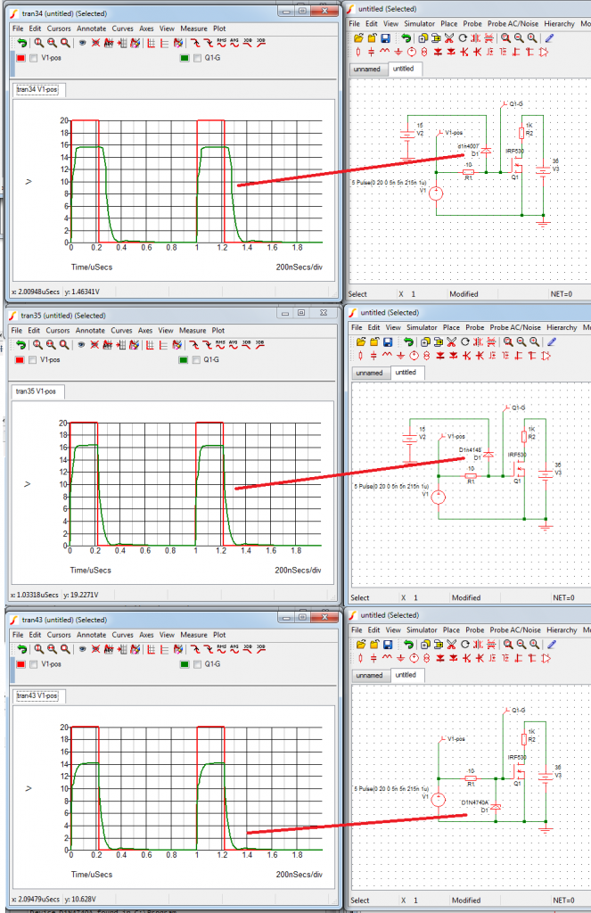
                              In your circuit, I am concerned about 2x diodes at gates of FETS, 1N4007. This diode has poor switching properties and is NOT normally used for fast switching. You get better switching characteristics with 1N4148 diode.
                              See graphs below. I do know you are concerned about momentary high current at the gate also, several amperes to charge the gate capacitance and 1N4148 might not handle the current.

                              I normally use a zener diode at the gate for protection since it is fast and also protects against negative voltage at the gate. This is the third graph in the picture below. Additional benefit is that there is also one less wire going to the FETs.

                              We all have basically the same goal here and I just thought I might warn you about those 2x diodes.

                              Lester

                              Comment


                              • Hi Lester,
                                thanks for suggestions. I have absolutely no problem to be corrected! And you are terribly right: we have the very SAME goal!
                                Well:
                                Using 1n4007 was superficial, just copied from elsewhere. You are absolutley right with your suggestion for 1N4148. I will correct it today.

                                Zener diode: Yes you are right with this suggestion but I do not trust in pure zeners in respect of accuracy and speed. We had bad experience with those. If the data sheet does not tell about a proprty for a component -> vote it to be bad and may vary from lot to lot, though the simulation shows nice results.
                                But I still agree given we suggest suppressor diodes. Those are made to swich very fast and are rated with better accuracy. Do you accept BZW06- 12 or BZW 06-15? datasheet

                                May I direct you to the capacitance of about 1.5nF? That is terribly for high switching speed.
                                I would suggest to replace 1N4007 by 1N4148 and feed the cathode to a BZW06..... Thus we get rid of the capacitance and make use of zener effect.

                                Please utter your opinion!
                                JohnS
                                Experts spend hours a day in order to question their doing while others stopped thinking feeling they were professionals.

                                Comment

                                Working...
                                X