Announcement

Collapse
No announcement yet.

My Motors got me to Tap into Radiant Energy

Collapse
X
 
  • Filter
  • Time
  • Show
Clear All
new posts

  • Originally posted by kassadum View Post
    Hi all (especially ufo)

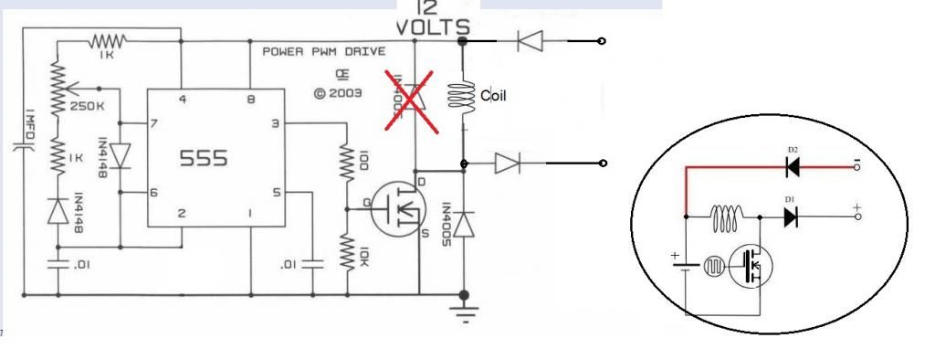
    After reading this post im at the point of starting my own crcuit
    I decided to start with the 1. version of ufos pwmcircuit.
    I hope i got it right:

    1. u need a stable 12v source
    2. next step is too turn it into a pwm signal and amplify it
    3. then u use a coil to "filter" out the hot part

    i hope i got it right because i am a little noob in electronic (only know the basics)
    that means soldering and connecting or using meters or osciloscope is not the problem

    The problem for me here in austria however is getting the parts....

    i only know rs and conrad but i cant find the requierd parts (especially the 555?)

    plz can anyone link me the parts required from one of these resellers?(its somehow confusing if u dont no the required specs of the parts due too not having the understanding in electronics)

    thx in advance


    i want too use this basic scematic first.(i hope thats the way to go)
    Hello Kassadum, hello all, i have pretty much UFOpolitics circuit in Multisim. Maybe it helps and see a little.
    tomturbo80's Library | Photobucket
    https://www.distrelec.at/home
    there are all the parts for this circuit.

    At UFO, Johnstone, Machine ..... Thank you for all your hard work and dissemination to all. Thank you and best success for the future, the turn will come soon. Love greetings tomturbo80

    Comment


    • Hi Kogs,
      I spent the day yesterday with target 3001 and today I see that you are "flying". Thankyou very much for the great work.
      Regards,
      bro d

      Comment


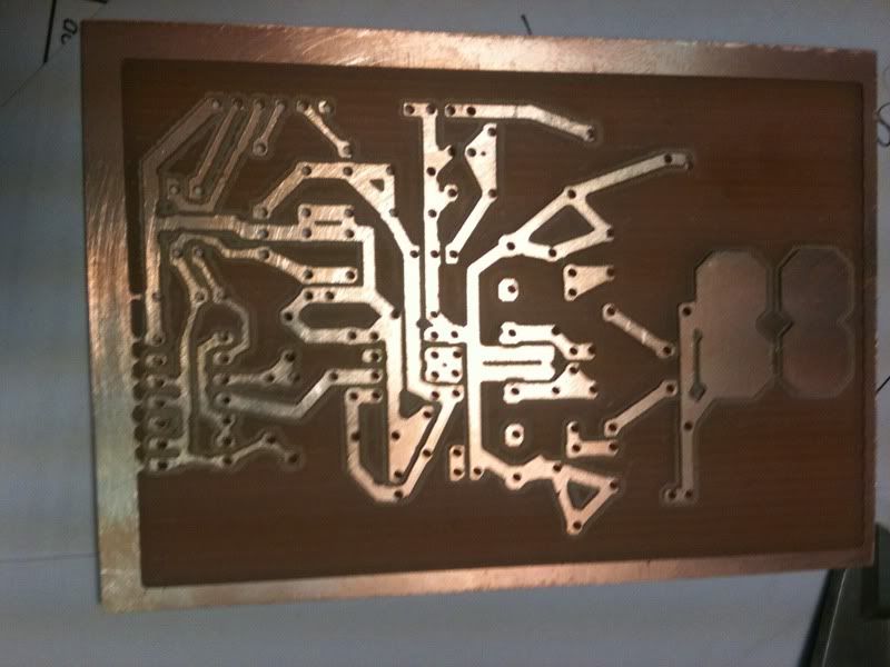
      • Monster Circuit V5.1 PCB

        Hi JohnStone
        I thought you would get a kick out of knowing that your 3001 program produced the code for this relieved PCB milled in Mach3 on a Taig. It took just over an hour to produce this one. Now I have four. Thanks for your help. I am looking forward to seeing what you find when you get yours together. We are all better off with you sharing as you do.
        Thanks
        Dana
        "Today's scientist have substituted mathematics for experiments and they wander off through equation after equation and eventually build a structure which has no relation to reality."
        Nikola Tesla

        Comment


        • Looking good there Dana. Have you tried pulsing it yet? I hooked up the two 300 v fets, and they worked good at 36v. Still only around 3000 Rpm. Used two neons at ds, no lighting, but kept the duty and frequency up. I wonder what RPM 48 or 60v gives.

          Comment


          • 5a ?

            Hello John Stone and all, am still gathering parts for pulsers,( still waiting on stuff to finish Rotor ), Bi-Directional diode has gone to back order, P6KE250CA, am trying to find alternative.

            Have found some with same voltage specs but all have lower amp rating. The spec on the P6K is 9A, is this a necessary requirement or will say 5A suffice?.

            Regards Cornboy.

            Comment


            • Originally posted by Cornboy 555 View Post
              Hello John Stone and all, am still gathering parts for pulsers,( still waiting on stuff to finish Rotor ), Bi-Directional diode has gone to back order, P6KE250CA, am trying to find alternative.

              Have found some with same voltage specs but all have lower amp rating. The spec on the P6K is 9A, is this a necessary requirement or will say 5A suffice?.

              Regards Cornboy.
              We do not talk of amps here! We talk of minute mA / low capacity and fast action in order to reopen FET in case of threatening overvoltage. This is an emergency case. P6KE -> 600W peak is of no use here.
              There is a reason to not use normal zener diodes - we need low capacity in order to have FETs switching fast.
              Try to get 1.5KE250CA (1.5 KW) or P4KE250CA (400W) = preferred or BZW04-213B.

              @ALL: Please keep in mind those diodes fit to FETs with Uds = 600V/ 650V. You need to adapt if you use other ones. i.e. use one protection diode only if you use FETs in the range of 300V.
              You might observe this driver is a well tuned unit. You may change anything, you may trespass any law - but you need to do it in a smart way in order to succeed!

              @Machine: Thanks for using neons for indication of overvoltage
              JohnS
              Experts spend hours a day in order to question their doing while others stopped thinking feeling they were professionals.

              Comment


              • Originally posted by prochiro View Post
                Hi JohnStone
                I thought you would get a kick out of knowing that your 3001 program produced the code for this relieved PCB milled in Mach3 on a Taig. It took just over an hour to produce this one. Now I have four. Thanks for your help. I am looking forward to seeing what you find when you get yours together. We are all better off with you sharing as you do.
                Thanks
                Dana
                Hi Dana,
                I like this PCB!
                Hints:
                • Cover the wires at right side area with solder in order to get low impedance.
                • Do not use an IC socket for driver. It is essential to drive short und low impedance.
                • Try without gate resistors first - use a wire jumper. Test with resistive load and short battery wires first. Motors oscillate themselves when pulsed thus we can not detect those killing oscillations from FET.
                • Connect a big cap (if available) between load + and GND near to load / FET.
                • Resisitve load: Get a bulb from head lamp H4 (or two H7), parallel filaments and connect as load with short wires. You can pulse it at 36V with 40% duty and get plenty of amps for testing while not overloading the bulb.
                • Take scope shots of gate and drain, post them and let's discuss them.


                BTW: I own a mill as well but had no time left since long time to build a controller. So I will build my board myself.
                I still have no material. Farnell informed after I placed the order they refuse to deliver for private use. Fortunately there are other sources available.
                JohnS
                Last edited by JohnStone; 02-20-2013, 08:09 AM.
                Experts spend hours a day in order to question their doing while others stopped thinking feeling they were professionals.

                Comment


                • Just let me know.

                  Hello John, if you need any components,you can't source locally, i can send them to you, no problem, i have ordered parts from Germany and had no freight problems.

                  It may not be a truck load of Garlic, but you deserve any help i can give.

                  Warmest Regards Cornboy.
                  Last edited by Cornboy 555; 02-20-2013, 11:05 AM.

                  Comment


                  • Originally posted by Cornboy 555 View Post
                    Hello John, if you need any components,you can't source locally, i can send them to you, no problem, i have ordered parts from Germany and had no freight problems.

                    It may not be a truck load of Garlic, but you deserve any help i can give.

                    Warmest Regards Cornboy.
                    Thanks, there are other local sources here. I relied in Farnell because they took the order without any complaints and after 2 weeks they detect that they refuse to sell to private persons. I have now my order at a reliable source underway - some bucks cheaper as well.
                    rgds JohnS
                    Experts spend hours a day in order to question their doing while others stopped thinking feeling they were professionals.

                    Comment


                    • Thx for help

                      Hi

                      1. thx for the quick reply too john stone and tomturbo.

                      i found almost all parts the only question are the 2 diods from the coil too motor and back (i guess they have to be 500v? and 75amp?)

                      also the npn mosfet transistor 500V 75amp with fast switching time 10ns?

                      also the 2 caps q1 are too ajust the frequency of the 555
                      like 1u for 1khz,10u for 100hz, 100n for 10khz ,and 10n for 100khz?

                      the variable resistor schould be high precision-linear 250kohm?

                      last but not least the resistors have too be "kohleschichtwiderstände" sry dont know the word in english?

                      also the 1mfd in the scematics i gues is the battery?

                      greets

                      kassadum

                      Comment


                      • Hi Kassadum,
                        I suggest you mix different circuits. In your prior post you refer to UFOs initial circuit.
                        Please specify the exact schematic you refer to. Else you will get wired sugstions because of misunderstanding.

                        You do not need to buy those 75A FETs for first trials. Either you build those totorial pulsers or you go directly for my monster pulser - but less learning. You decide. Those tutorial circuit were discussed in detail before.

                        And yes those resistors are normal standard carbon film resistors (Kohleschichtwiederstände - German is very complicated sometimes) type 207 (2mm diameter / 7 mm length)

                        Hint for good dictionaries (all major languages): dicct.cc and Translations in context: Linguee

                        I found a good source for components in German speaking countries in Europe selling ALL items from Farnell but they sell to private persons as well HBE-Shop.de - Ihr FARNELL-Fachhändler. You will get almost any electronic part there. Be careful at parts from American stock -> they add censiderable shipping cost! HBE is superiour compared to Conrad!
                        JohnS
                        Experts spend hours a day in order to question their doing while others stopped thinking feeling they were professionals.

                        Comment


                        • Originally posted by kassadum View Post
                          Hi all (especially ufo)

                          After reading this post im at the point of starting my own crcuit
                          I decided to start with the 1. version of ufos pwmcircuit.
                          I hope i got it right:

                          1. u need a stable 12v source
                          2. next step is too turn it into a pwm signal and amplify it
                          3. then u use a coil to "filter" out the hot part

                          i hope i got it right because i am a little noob in electronic (only know the basics)
                          that means soldering and connecting or using meters or osciloscope is not the problem

                          The problem for me here in austria however is getting the parts....

                          i only know rs and conrad but i cant find the requierd parts (especially the 555?)

                          plz can anyone link me the parts required from one of these resellers?(its somehow confusing if u dont no the required specs of the parts due too not having the understanding in electronics)

                          thx in advance


                          i want too use this basic scematic first.(i hope thats the way to go)

                          Hi john sry for the inconviniece

                          i just reread the first sides of the post ufo used a MOSFET's N-Channel rated at 400 V Rds On 0.4 ohms witch would be this:

                          http://www.pollin.de/shop/downloads/D131021D.PDF


                          i meant the 2 diods on the very right side of the scematics leading from coil too the dc motor and back.

                          and on the very left side the imfd? is this the battery?

                          the rest i think is clear with the q1 i set the frecuency depending on caps.

                          ps: i think i start with the most basic scematic and work my way up because i never liked doing somthing without knowing why
                          thats why i was thinking about bying the stronger mosfets because i need them anyway later...

                          regards

                          kassadum

                          Comment


                          • Originally posted by Lester444 View Post
                            Hello UFO,

                            I have edited the circuit diagram to be consistent with the other diagrams in the first few posts. Just trying to avoid confusion with the other members. I hope you don't mind.

                            Lester

                            sry the scematics got lost somehow

                            Comment


                            • Mirror?

                              Originally posted by prochiro View Post
                              Hi JohnStone
                              I thought you would get a kick out of knowing that your 3001 program produced the code for this relieved PCB milled in Mach3 on a Taig. It took just over an hour to produce this one. Now I have four. Thanks for your help. I am looking forward to seeing what you find when you get yours together. We are all better off with you sharing as you do.
                              Thanks
                              Dana
                              Hi Dana,

                              I need to be sure of something regarding etching these ccts.
                              I was just about to post regarding your previously posted etching, because when I etched mine I could read the text in the copper.

                              I noticed that your pics do not appear to be the mirrored image etched on the pcb.
                              Your pics are the same as the image appears in the pdf, which is the mirrored image unless I am mistaken.
                              Perhaps you mirrored your pics ..........

                              When I am looking at my etched pcb, the text "Monster Driver v5.1" is in the upper left hand corner. Yours (if the text was visible) would have to be in the lower right, with the heavy copper connectors on the right in both cases.

                              I have to look through the component side for mine to line up with yours.

                              Shouldn't I be able to read the text after etching?

                              Regards,

                              Donald
                              Last edited by Donald Haas; 02-20-2013, 06:07 PM.

                              Comment


                              • Donald,
                                please note there are two different sets of data available:
                                Initial realease as PDF:
                                http://www.energeticforum.com/renewa...tml#post224329
                                Same release but manufacturing data being generated automatically by CAD: http://www.energeticforum.com/renewa...tml#post224748

                                Some text was entered in PDF manually for explanation. Thus it is no wonder to have some differences being of no importance for the layout. But I admit you are very attentive!

                                Sorry for confusion!

                                Please do not use grafic dataout of my V4 PDF for layout. I will revide it soon to be conforming V5.1 version.
                                JohnS
                                Experts spend hours a day in order to question their doing while others stopped thinking feeling they were professionals.

                                Comment

                                Working...
                                X