Announcement

Collapse
No announcement yet.

My Motors got me to Tap into Radiant Energy

Collapse
X
 
  • Filter
  • Time
  • Show
Clear All
new posts

  • secondary

    Greetings UFO builders and pilots My coil operates fine as air core but now i,m interested in a secondary and a steel pipe core. But i'm not sure if the steel core goes inside the primary and then the sec goes inside the steel core, or does the sec go inside the primary and then the pipe goes inside the sec? PS i wonder if anymore is ever going to be said about the ALIEN COIL?

    Comment


    • Originally posted by JohnStone View Post
      Hi iankoglin,
      now I understand.
      But sorry the embedded files in MS Word do not open at my location.

      Regrading your setup.
      - Generator SG...circuit with 2 times 4 optos
      - driver 555 with transistors
      - FETs: please regard them to be rated for 5.6A at 100癈!!!!! and 0.5Ohm each. You might devise tests with pure resistiver loads (see my recent posts regarding car head lamps being pulsed) in order to see how your setup behaves with 2 FETs (pease connect them similar to the monster driver (gates to be close together). Check for temperature at 10.
      JohnS
      G'Day John
      I like your new Avata will miss the old John in stone

      Kogs

      Comment


      • Originally posted by JohnStone View Post
        Hi iankoglin,
        in your vid the circuit diagram of happy motor is not clear. Did you post it already anywhere. I'd like to review your setup in order to gather knowledge.
        Thanks
        JohnS
        G'Day John
        All My Friends call me Kogs
        Here is my pic in Dropbox
        https://www.dropbox.com/s/rlj9hhii7p...HappyMotor.jpg

        Also here it is ji Photobucket


        Kindest Regards

        Comment


        • Monster V5.1

          @ JohnStone

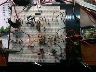
          Your going to love this and hate this. It works great even with one cool fet, but as you can see on breadboard, long thin wires. I am using 18V source for this test and running a Electronic Goldmine 24 V motor.


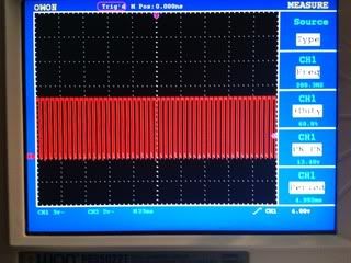
          It runs well with no heat at 18V, which is at 95% duty cycle. Due to small wires, I'm not going to run a larger motor with this, it was just a setup I made to test some of the configurations. I may use this setup to test the thermal sensor to override in Arduino duty cycle or shut motor off in a safe way if fets get too hot. Is that not a nice square wave or what? I would recommend to others building this circuit to first set it up on a board to better understand what does what. This works well but it was not my first or even second attempt. Save solder and use a board but do not crank it up until transferred to correct configuration.
          Dana

          Total Photobucket album
          Prochiroone's Library | Photobucket
          "Today's scientist have substituted mathematics for experiments and they wander off through equation after equation and eventually build a structure which has no relation to reality."
          Nikola Tesla

          Comment


          • Hello Dana,

            Thank you for responding to my query, should have been more specific, I did scan post 3923 by nico8k last week (before I was the proud owner of a nano) and was able to see the three .jpg's but was unable to view the .fzz or .ino file, so no code to learn from . . .
            after your showing a replication, took another look in his dropbox - Still unable to download or view the NicoPWMSwitch.fzz or NicoPWMSwitch.ino from his dropbox to my PC.

            Guessing it's an ISP trouble on my end because I found a workaround.

            Was able to copy the files from his dropbox to my dropbox - can see them now,
            so we will study his code and be ready to try it after finishing the replication of Sir JohnS's Monster Driver V5.1 .

            I'm a bit old school (analog) - thats why I wanted to use pots but with you and Nico having working circuits . . . it's time to get behind buttons.

            Thanks again for making me take a second look.

            Hitby13kw


            Originally posted by prochiro View Post
            Both he and I use push buttons instead of pot as it is much more accurate in both frequency selection and duty cycle selection as well as a better tighter square wave. He shows how to put it on a breadboard in post 3923 and here I have a picture of it on top level of arduino. Note the simplicity.
            http://i1079.photobucket.com/albums/...psdf4a27bb.jpg
            Dana

            Comment


            • The activity of the animal beings has become acutely active everywhere on this earth. Bodies do not get time to booty a blow for a while. With the accretion use of altered gadgets of gps signal jammers, the possibilities of accepting the aboriginal of blow accept absolutely finished. The adaptable phones or the corpuscle phones are some of these accessories that accumulate the bodies consistently in blow with the alfresco world. The adaptable building are additionally accessible about everywhere these canicule and due to this the accessibility of the Cell Phone Jammer has become alike added quick and authentic. Today, you cannot break out of ability of these adaptable building as their signals can bolt your about anywhere. The bearings of bodies who accord to altered business professions has become actual analytical of wifi jammer as their authorities bolt them anywhere any moment.

              Comment


              • Originally posted by nellschmertz View Post
                The activity of the animal beings has become acutely active everywhere on this earth. Bodies do not get time to booty a blow for a while. With the accretion use of altered gadgets of gps signal jammers, the possibilities of accepting the aboriginal of blow accept absolutely finished. The adaptable phones or the corpuscle phones are some of these accessories that accumulate the bodies consistently in blow with the alfresco world. The adaptable building are additionally accessible about everywhere these canicule and due to this the accessibility of the Cell Phone Jammer has become alike added quick and authentic. Today, you cannot break out of ability of these adaptable building as their signals can bolt your about anywhere. The bearings of bodies who accord to altered business professions has become actual analytical of wifi jammer as their authorities bolt them anywhere any moment.
                Hi nellschmertz,
                supposingly you entered the wrong thread. Sorry, your contribution is off topic totally. Please delete your post. You might return if you are interested in our topics being discussed here.
                JohnS
                Last edited by JohnStone; 02-27-2013, 10:37 AM.
                Experts spend hours a day in order to question their doing while others stopped thinking feeling they were professionals.

                Comment


                • Originally posted by iankoglin View Post
                  G'Day John
                  All My Friends call me Kogs
                  Here is my pic in Dropbox
                  https://www.dropbox.com/s/rlj9hhii7p...HappyMotor.jpg

                  Also here it is ji Photobucket

                  Two things to remember are the coils are to be wound exactly the same direction and they are NOT BIFILAR The Cold/Green coil is wound First then the Hot/Red is wound ON TOP and is important to have all the 4 fast Diodes set in the right direction even though some think they are back to front

                  Kindest Regards

                  Comment


                  • Originally posted by prochiro View Post
                    @ JohnStone

                    Your going to love this and hate this. It works great even with one cool fet, but as you can see on breadboard, long thin wires. I am using 18V source for this test and running a Electronic Goldmine 24 V motor.


                    It runs well with no heat at 18V, which is at 95% duty cycle. Due to small wires, I'm not going to run a larger motor with this, it was just a setup I made to test some of the configurations. I may use this setup to test the thermal sensor to override in Arduino duty cycle or shut motor off in a safe way if fets get too hot. Is that not a nice square wave or what? I would recommend to others building this circuit to first set it up on a board to better understand what does what. This works well but it was not my first or even second attempt. Save solder and use a board but do not crank it up until transferred to correct configuration.
                    Dana

                    Total Photobucket album
                    Prochiroone's Library | Photobucket
                    Hi Dana,
                    I love your setup. You prove my teaching was usccessfully. You dare to trespass laws of physics but you are aware it this a violation and in case of problems you know what to change.
                    It is advisable in any case to do such setup first (with knowledge) and learn and prepare for a stable PCB in second step.
                    I hope more of you act same way. I include YOU watchers of this thread being inactive as contributors!

                    Dana: Will it be possible to measure rise and fall times of this seemingly superb signal? Per defnition it its the time from 10% up to 90% of amplitude. (ohmic resistance please)

                    BTW: Required gate drive power increases with increasing power being switched. Actions at drain counteract gate activity. Thus: High and steep voltage swing at drain overrides weak gate driving. Imagine: inertia when acceleratingn and decelerating a mass - same behaviour.

                    BTW: I struggle strongly with Arduino just now. I want ot gather knowledge in order to supply some good means of control later on.
                    JohnS
                    Last edited by JohnStone; 02-27-2013, 07:06 PM.
                    Experts spend hours a day in order to question their doing while others stopped thinking feeling they were professionals.

                    Comment


                    • UFO, John S, Dana, and Kogs,

                      Good looking drawing.

                      I have posted two new pics on my Photobucket album:

                      bobfrench's Library | Photobucket

                      The top two pics are the circuit and the device running a 65W CFL and a string of Christmas LED lights on a "one wire" HV output. The input is 120mA of 12v. The output is around 1200v. This was developed from an Imhotep thread started in '08 and is the simplest circuit that I have ever seen. We are calling this embodiment the IROC 2. I can light NE-2s almost anywhere on the circuit and the guy that turned me on to this has his Primary battery never going down. I don't have that yet and am trying to find out what the difference is between our setups.

                      I'm putting this out because it may come in very handy in conjunction with the other projects, motors, etc. I have been in touch with the UFO projects through Dana and am sorry that I have not been able to contribute for some time now. I am trying to get the Bearden experiment done for months and have been held up with the programming of the Arduino lately. If you know someone that can help me with a very simple programming problem, please send him my way.

                      Good luck,

                      Bob

                      Comment


                      • @ JohnStone

                        John, here are the rise and fall times but as you know this is a less than perfect system. This measurement was taken with 18V supply with 160 Hz and 50 Duty. The rise and fall did not change with any frequency change up thru 22 KHz and tested with Arduino pulser.
                        Rise Time 40 us
                        Fall Time 40 us
                        These numbers are from scope which may be total rise and not your 10/90 method. Is not 40 microseconds for the whole thing in the ball park?
                        These push buttons let you dial in exact numbers but may not be the fastest thing to get from start to high speed.
                        Dana
                        Last edited by prochiro; 02-27-2013, 11:06 PM.
                        "Today's scientist have substituted mathematics for experiments and they wander off through equation after equation and eventually build a structure which has no relation to reality."
                        Nikola Tesla

                        Comment


                        • Originally posted by sampojo View Post
                          My reservations on sinking the money on high power motors is hopefully only temporary and comes only from limitations of my time, electronics skills, and electric motor knowledge and skills, which I am progressing on. Every free moment off my full time job is going toward this. Thanks so much for any repeat information. I spend much time slogging thru the randomness of thread based technical information but still cannot find some things.

                          This is exactly what I was looking for. Thanks immensely. What genius! I had been just reading between lines on posts referring to coils surmising that this is what Ufo was doing. I couldn't imagine where to start hooking things up.


                          Yes indeed, Ian

                          So, Ufo has posted that the plan was to use the coil motors as opposed to an additional (simple non-twisted bifilar, I think?) coil. Probably the generator side of a motor and/or the generator coils in a motor-generator hookup. But where on the Blackchisel updated Ufo circuit would the coil be hooked up? THIS IS NOT Blackchisel's corrected CIRCUIT IT SHOULD BE THE one I SHOWED in the ORIGINAL Post how come you inserted a different one


                          So it is intriguing to me to use the additional coil and I have read a post recently where he has recommended steel core over air core. Should I take that as the best in all cases, do you know? The motor goes to the +12v and ground I suppose? Is this wrong? Would that be because radiant is introduced? On his videos of some motor tests, no controller were yet introduced but that meant a full 36v was being applied.

                          Where would a controller be inserted in the happy motor dgm?


                          I feel like I have to pinch myself once in a while to make sure I am not in some sort of fairy tale dream about free energy

                          I will understand if I am like the kid with 20 questions...

                          TIA
                          G'Day sampojo

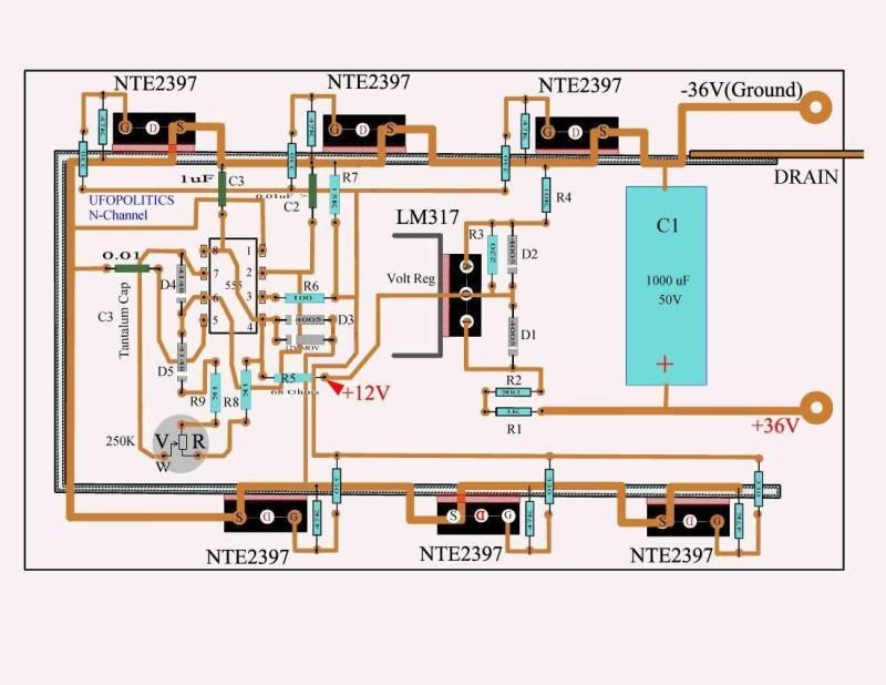
                          I do not know how you have here the original UFO original controller instead of the Blackchisel Updated one here
                          https://www.dropbox.com/s/rlm9u90bnf...ckchisel97.jpg

                          Notice the extra Land connecting D3 to Source this is missing in UFO's original controller

                          Again here it is In my Photobucket


                          Kindest Regards Kogs


                          Kogs cant download images from Dropbox
                          Last edited by iankoglin; 02-28-2013, 01:36 AM. Reason: Correction

                          Comment


                          • Hi All,
                            I received my


                            IPW60R041C6 INFINEON 10PCS TO-247 $2.00

                            plus shipping.

                            30 pieces for me in New England was slightly under $100.

                            Only a few days after shipping.

                            There was a delay due to Honk Kong hollidays.

                            Cantact:

                            Betty

                            Top Source Technology Co.,Ltd
                            Tel : (86)--755-83586635 Fax : (86)--755-83972235
                            E-mail : tst@vip.163.com Msn : betty.tst@hotmail.com
                            Skype : betty .tst
                            Website: 无标题文档 or Shenzhen Top Source Technology Co., Ltd. - Electronics Component,Integrated Circuit,IC Parts

                            Comment


                            • Good One.

                              Originally posted by Donald Haas View Post
                              Hi All,
                              I received my


                              IPW60R041C6 INFINEON 10PCS TO-247 $2.00

                              plus shipping.

                              30 pieces for me in New England was slightly under $100.

                              Only a few days after shipping.

                              There was a delay due to Honk Kong hollidays.

                              Cantact:

                              Betty

                              Top Source Technology Co.,Ltd
                              Tel : (86)--755-83586635 Fax : (86)--755-83972235
                              E-mail : tst@vip.163.com Msn : betty.tst@hotmail.com
                              Skype : betty .tst
                              Website: 无标题文档 or Shenzhen Top Source Technology Co., Ltd. - Electronics Component,Integrated Circuit,IC Parts


                              Great score Donald, i already have my fets and they seem quite dense, they weigh around 6 gram each, and are made in Thailand, are your's the same?

                              I will order some backup fets from your supplier if they work fine.

                              Warm Regards Cornboy.

                              Comment


                              • Originally posted by Donald Haas View Post
                                Hi All,
                                I received my


                                IPW60R041C6 INFINEON 10PCS TO-247 $2.00

                                plus shipping.

                                30 pieces for me in New England was slightly under $100.

                                Only a few days after shipping.

                                There was a delay due to Honk Kong hollidays.

                                Cantact:

                                Betty

                                Top Source Technology Co.,Ltd
                                Tel : (86)--755-83586635 Fax : (86)--755-83972235
                                E-mail : tst@vip.163.com Msn : betty.tst@hotmail.com
                                Skype : betty .tst
                                Website: 无标题文档 or Shenzhen Top Source Technology Co., Ltd. - Electronics Component,Integrated Circuit,IC Parts
                                G'Day Donald
                                Thanks for the link I will order some

                                Kindest Regards My Friend
                                Kogs

                                Comment

                                Working...
                                X