Announcement

Collapse
No announcement yet.

My Motors got me to Tap into Radiant Energy

Collapse
X
 
  • Filter
  • Time
  • Show
Clear All
new posts

  • Hello John, my scope is Atten ADS1102CML 100Mhz, the probes are switchable between 1x & 10x, it's not an expensive one, hopfully it will do all i need.

    I have some SiC diodes on the way, and will go back to original, pulsing coils, for radiant output, when Monster is finished. This is where i left off, lighting 10 25W 240v CFL's, when my pulser Fried.

    Hopfully the no reverse time characteristic, of the SiC diodes, will help protect my new fledgling Monster baby.

    Once again, thanks for your time and devotion here John,

    Warm Regards Cornboy.

    Comment


    • temperature sensor array

      Originally posted by JohnStone View Post

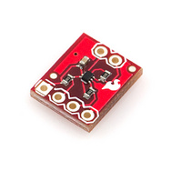
      Found a I2C level shifter at sparkfun:
      You need to add it once to the temp sensor branch. Then you can use multiple TMP102 -> being of 3.3V type. You need to add 3.3V poswer supply (might come from Arduino):


      I ordered yesterday TC74A for €2.08 each at Farnell Element14 alias Newark. They are I2C, need a cheap insulation kit but are dedicated to be attachted to solid objects. (housing TO220 - like voltage regulators 7805 or 7812) (see my post #2337

      JS


      Hi John,
      I ordered some of the tc74a sensors from Allied but they didn’t have any in stock & could give me no idea when they would get them, placed the order anyway, but am still looking for other ways to skin the cat . . . (hence my last message)

      Mfr. Part#:TC74A0-5.0VAT Allied Stock#:70046378 Microchip Technology Inc. - TC74A0-5.0VAT - Semiconductors - Sensors - Allied Electronics
      Mfr. Part#:TC74A3-5.0VAT Allied Stock#:R1137547 Microchip Technology Inc. - TC74A3-5.0VAT - Uncategorized - Allied Electronics
      Mfr. Part#:TC74A5-5.0VAT Allied Stock#:70046380 Microchip Technology Inc. - TC74A5-5.0VAT - Semiconductors - Sensors - Allied Electronics

      Just love the Level shifter you found, this would probably be a bit more reliable than the zener diode trick I’m currently using .. . .

      Still plugging away with your PM, sometimes I confuse myself as the BT talks on the same bus you program the Arduino with ~ (my programing skill is not as good as Garry’s)

      Hitby13kw

      Comment


      • Hello Hitby RS components, seem to have all 3 TC74A's in stock, don't know if you have access to them!

        Regards Cornboy.

        Comment


        • Kogs update

          Originally posted by Midaztouch View Post

          Hey kogs,

          do you have an emergency HV kill button
          Richie
          G'day Richie and the rest of the team


          I guess the normal wind Chinese motor 250 w 36v is just not strong enough as I told my driver not to use the throttle until she has a bit of speed then she can power the throttle. She said it didn't work so I tried it again and found the throttle would delay to stop the motor for a second even though it returned fully It did stop though
          I took it back to my workshop and decided to give it a test once again just to be sure I switched the battery switch on AND GUESS WHAT HAPPENED NEXT


          http://s1193.photobucket.com/user/Kogs1/media/Kogs%20UFO%20Projects/IMG_0080.jpg.html?filters[user]=115261574&filters[recent]=1&sort=1&o=0

          Some people have to Just Learn the hard way

          I took the circuit out and set it up on my bench as soon as I switched on the power the motor sprung to life full bore, the LED was off when the pot was zero and would blink slow and increased as I increased the pot. The motor was full bore I switched it off and examined it.

          The Monster driver 1 ohm resisters were cooked one Mosfet was dead the other tested working? I imagined that as the LED was blinking that the Oscillator and the first part of the monster driver was OK I replaced the Mosfets and the 1 Ohm resistors and set it up again on my bench. This time nothing happened not even the LED.

          I did not test the Diodes.
          What I will do now is make another couple of Monster 5.1's circuit boards and follow through with the installation instructions as John Stone is so kindly giving us thanks John.

          I have run My EVBike1 several times now and have noticed that each time I charge the 36v battery(3 x 7.2ah12v SLAB's) it seems to last a bit longer and it takes less to charge it. When I charged them the first time it took 24 hours the second time 22 hours and they seem to have more power that is it takes a bit longer to run down to a point where it effects the motor speed ( below 30v) I am using my build of John Bedini's Solid state energiser I have restored Quite a few defunct batteries with it. The only trouble I have with it is it is a pain to keep an eye on the charging volts I really need an automatic cut out when the battery reaches it's DOC

          I remember that when I purchased 12 6v Trojan batteries they did not have much capacity and when I read the manual it said that new Lead acid batteries take quite a few cycles to reach their best capacity.

          My progress is to order 2 more 250w Chinese motors so I can wind them asymmetrically and when I have that done I can then do the comparison
          to just see the difference.
          My think I need to order 4 more motors as my test driver has already commandeered EVBike1 as she asked me "Will she be able to ride it every day" I need one my self so I can exercise every day.

          Kindest Regards


          Kogs trying to be careful

          Comment


          • Ohhh, KOGS, thanks for that image, after i picked myself up of the ground, i thought Glad no one got hurt.

            I am sure asymmetrically wound motors will leave much bigger and better donuts on your gravel. Just kidding.

            Thanks for sharing, friend.

            Warm Regards Cornboy.

            Comment


            • Originally posted by iankoglin View Post
              G'day Richie and the rest of the team


              I guess the normal wind Chinese motor 250 w 36v is just not strong enough as I told my driver not to use the throttle until she has a bit of speed then she can power the throttle. She said it didn't work so I tried it again and found the throttle would delay to stop the motor for a second even though it returned fully It did stop though
              I took it back to my workshop and decided to give it a test once again just to be sure I switched the battery switch on AND GUESS WHAT HAPPENED NEXT


              http://s1193.photobucket.com/user/Kogs1/media/Kogs%20UFO%20Projects/IMG_0080.jpg.html?filters[user]=115261574&filters[recent]=1&sort=1&o=0

              Some people have to Just Learn the hard way

              I took the circuit out and set it up on my bench as soon as I switched on the power the motor sprung to life full bore, the LED was off when the pot was zero and would blink slow and increased as I increased the pot. The motor was full bore I switched it off and examined it.

              The Monster driver 1 ohm resisters were cooked one Mosfet was dead the other tested working? I imagined that as the LED was blinking that the Oscillator and the first part of the monster driver was OK I replaced the Mosfets and the 1 Ohm resistors and set it up again on my bench. This time nothing happened not even the LED.

              I did not test the Diodes.
              What I will do now is make another couple of Monster 5.1's circuit boards and follow through with the installation instructions as John Stone is so kindly giving us thanks John.

              I have run My EVBike1 several times now and have noticed that each time I charge the 36v battery(3 x 7.2ah12v SLAB's) it seems to last a bit longer and it takes less to charge it. When I charged them the first time it took 24 hours the second time 22 hours and they seem to have more power that is it takes a bit longer to run down to a point where it effects the motor speed ( below 30v) I am using my build of John Bedini's Solid state energiser I have restored Quite a few defunct batteries with it. The only trouble I have with it is it is a pain to keep an eye on the charging volts I really need an automatic cut out when the battery reaches it's DOC

              I remember that when I purchased 12 6v Trojan batteries they did not have much capacity and when I read the manual it said that new Lead acid batteries take quite a few cycles to reach their best capacity.

              My progress is to order 2 more 250w Chinese motors so I can wind them asymmetrically and when I have that done I can then do the comparison
              to just see the difference.
              My think I need to order 4 more motors as my test driver has already commandeered EVBike1 as she asked me "Will she be able to ride it every day" I need one my self so I can exercise every day.

              Kindest Regards


              Kogs trying to be careful
              Hi kogs!

              First of all, I'm glad you are ok. But I know it felt good to have some real excitement!

              Well, I seen some of the 1000watt motors bring bikes to good speeds! Remember lead acid batteries have a very low c-rating. Having low or poor motor preformance is usually do the lead batts. Lipos usually bring the motors to life.

              From our past data using the quad pulser, the asymmetric motor will have a lot lower amp draw = better Performance from lead batteries.

              Just some food for thought! Keep moving forward!

              Midaz

              Comment


              • @Hitby: What a mess! The only easy to use I2C temp sensor in the world is not available. What do all those tinkerers in the world?
                I got today most of my materials ADC, current sensors, TC74A?-5.0VAT (Farnell, Newark). Arduino Leonardos still missing (China) and John Stone V5.1 PCBs from Oshpark.
                Regarding serial: Leonardo has two serial: (processor 32U).
                • For programming USB only. This is "serial"
                • For serial over pins (for i.e. BT) it uses "serial1"

                Leonardo supports emulation of USB Keyboards and mice at USB.

                All other arduinos with 328p processor (uno, nano..) have only one
                serial over pins and there a USB slave chip is connected.

                @Kogs: I am so sorry you lost FETs and possibly FET driver. Still pondering what happens. You are not the only who fell into this pit. You all will get some thoughts at next tutorial session. Am quite busy now with a new project at my work.
                If you repair your driver please replace 1Ohm gate resistors with 33 or 47 Ohm. They need to be tuned to every application. They shall dampen possible oscillations from drive circuit. It is a negatiantion between speed, stability and heat. Please observe heat with those resistors.
                Your pic: Nice you are still well. Sorry for aliens will not see your drawings in gravel from space. See for reference those Nazca patterns in America - being somewhat more prominent

                You might want to look at our data aquisition system. It is suitable for battery charger as well along display of charged energy.

                @Cornboy: Your scope is fine. I'd like to have it. It is worth to spend time with it in order to master it. I got the manual from Atten and they have some basic exercises in it you can do. Unfortunately all tutorials in internet for scopes ralate to those older ones (like mine) with dials. Menue driven scopes are very individual in handling. But for now it is suffitient if you see your signals.
                JS
                Last edited by JohnStone; 08-30-2013, 10:39 AM.
                Experts spend hours a day in order to question their doing while others stopped thinking feeling they were professionals.

                Comment


                • Not Snoozing.

                  Hello JS, i am using scope to look at pulse generator, and RMcybernetics pulsers etc, starting to get the hang of it.

                  Trying not to use the Granny, snooze, button tooo much.

                  Warm Regards Cornboy.

                  Comment


                  • pictures

                    @cornboy
                    Hi Cornboy,

                    I am not too proud of my machine work and when I see all of the beautiful machinery that you and the others are sharing on this site I am humbled. But you asked for pictures of what I am doing and so if you think it will help here are a few.

                    This is a photo of my third replication prior to assembly. In the left rear corner you will see the lexan disc that I spoke of.

                    This is a close up of the lexan disc and the transmitter part of the infrared transmitter receiver pair that I am using for the tachometer and also to time the motor with.
                    https://www.dropbox.com/s/bx9wzv3ivqt66wj/DSCF0020.JPG
                    This is a picture of the assembled goldmine with the lexan disc mounted and the infrared transmitter receiver combo mounted. Not possible to see the transmitter in this photo as it is mounted underneath the motor.
                    https://www.dropbox.com/s/z55yyb6o1sns1uo/DSCF0021.JPG
                    In this photo you can see the transmitter through the lexan disc. Also the electrical tape that I am using for timing the motor to the pulser. Once the best timing has been discovered I will place masking tape on each side of the electrical tape and remove electrical tape and paint that area black.

                    These are the current replications that I am working on. These will be dual pentagon winds.

                    Hope this helps.

                    @ John Stone

                    I have elected not to go with the vane type of interrupter. I only want one signal per revolution as it is my intention that the motor needs to be controlled by code and not be the interrupts. This allows a great deal more flexibility between types of motors and it is easier to accommodate many types of motors and configurations of commutators and various brush pairs. As you can see in the photos above it is easy to implement this design and well within a novices reach. That is why I am doing it that way. Any more difficult and I might not be capable.

                    cheers,

                    Garry

                    Comment


                    • Good Work.

                      Hello Garry, your work looks great, practical experimenting and building, is the way forward, to learning, theory is only good to a point.

                      With my MAG3 build, i will start with very simple switching signals to monsters, from 3 vane sensors, mounted on a plate that is adjustable. The vane will have 36 cutouts, as the Wound stators will need to be pulsed 36 times per revolution, along with the rotor.

                      Of course this is after initial testing with linear feed, at different voltages.

                      I want to get a feel for the motor, before jumping into arduino control.

                      It would be ideal if the signal from the vane sensors, before reaching the monster opto's, was duty cycle adjustable, maybe, Please, if you or JS had a moment, you could design a simple circuit for me?

                      Keep up the good work and warm regards,

                      Cornboy.

                      Comment


                      • Originally posted by GChilders View Post
                        .....
                        @ John Stone

                        I have elected not to go with the vane type of interrupter. I only want one signal per revolution as it is my intention that the motor needs to be controlled by code and not be the interrupts. This allows a great deal more flexibility between types of motors and it is easier to accommodate many types of motors and configurations of commutators and various brush pairs. As you can see in the photos above it is easy to implement this design and well within a novices reach. That is why I am doing it that way. Any more difficult and I might not be capable.
                        ....
                        Those words make it clear - especially your pics. Thanks. You see a chance to do all timing by program. That was exactly my question before but I figured to still need vanes per pole. Thanks for posting!
                        I assume you will come up with another great Arduino code where we can adjust firing angle by serial command.
                        JS
                        Last edited by JohnStone; 08-30-2013, 07:43 PM.
                        Experts spend hours a day in order to question their doing while others stopped thinking feeling they were professionals.

                        Comment


                        • Arduino code

                          @JS

                          I am already working on a new version that will accomplish this. I am creating an inner loop that will break down the number of pulses based on how many brush sets, and how many poles the motor has. There will be one pulse per pole in the new version which should be ready by the end of Sunday. I have been thinking about this since I built the lexan disc. I sent ufo a pm to see what he thought about this idea and he thought it would work very well. Anyway getting closer to being able to do some serious testing. Seems like you have been very busy between your tutorials and building your Chinese motor. Hope every thing is well with your wife. We appreciate the time that you are spending here with us and helping us as we muddle through the electrical bits of the technology.

                          Cheers,

                          Garry

                          Comment


                          • posting pictures

                            @all
                            I am having a problem with posting the pictures of the work. What is the secret that everyone is using to have the pictures come up without posting a link to them. I posted the link thinking that the pictures would be displayed with the text. The text came up but only links to the pictures. I would truly appreciate it if someone could help me here. I am using drop box and I noticed that the link was https: instead of http: I know that this is a secure encrypted version which is unnecessary because I am sharing them publicly.

                            Any help would be appreciated.

                            Cheers,

                            Garry

                            Comment


                            • Instructabel F: - Monster Driver

                              Today we focus on final part F -the real power unit.
                              We have two FETs in parallel in order to achieve safe current switching of about 100A. If this is oversized for your application please assemble only one FET along its associated componets. In fact I ask all of you to do it first in order to get clear test conditions. OK - let's focus on T1 and componetns around.

                              These FETs of N-type will conduct current if we switch voltage to gate (T1 pin1) referenced to source pin (T1 pin 3)
                              BTW: Why pin 3 is source while it is connected to battery GND? There is a damn simple answer. Our battery sources electrons at GND lead!! The real physical current flow is from GND to +. Based on historical facts we think in terms of so called "technical" current flow - reversed to reality. In fact old Japanese transistor circuits were drawn conforming physical current flow but nowbody abroad could read them. Later on they adapted the technical current flow.

                              You have successfully tested your FET driver and now you can be confident voltage WILL be switched to gate.

                              Pulldown resistors R5 / R6 are there for safety reasons. The FET shall be safely switched off if we have any interruption to FET driver. Gate insulation to source (pin3) and drain (pin2) is in range of gigaOhm that is more than some caps or PCB might have. Therefore we can not prevent some single electrons to escape to gate crowding there and eventually making the FET conductive.

                              Now let's look at those strange 1Ohm resistors. They serve for safety as well - minimizing unsolicited oscillatons in driver circuit.

                              Facts: A FET is much more faster in switching than the data sheet tells us. I talked of this tiem in last instructable. A FET is a circuti in itself and contains many unwanted (parasitic) but real capacitances. This is a side effect of semiconductor structures. If we control a FET intent ionally we need to charge and dicharge those internal caps - that takes time and makes the FET slow in swiching properties.
                              But there are cases where those caps enter a spurious oscillation. The traces to gate and gate pin itself are in fact minute inductances and together with internal gate cap they build up a nice tank circuit. While oscillating the FETis being switched rapidly along oscillations at every edge of switch action intended.

                              .
                              In case of oscillations apart from minor signal quality our FETs will suffer from heat problems. At every edge it sweeps over a range of mid resistance but increasing current (P = I*R^2).
                              You will not get these oscillations for sure but you never know when and where they occure. You might suffer of premature FET death.
                              As you know we can counteract oscillations with resistance. This is true in mechanic matter and electric as well.


                              Here R3, R9 come into play. They need to be tuned to be as low as possible and as high as to dampen oscillations. The value 1R is a place holder only. Some circuits need 5 Ohm others up to 47 Ohm. It can't be predicted.
                              If you have no scope please use 22 Ohm or 33 Ohm and check for heat later on.
                              If you own a scope you will start with 0Ohm (simple wire) and check for oscillations. Then you increase up to the state where you have no oscillations left. You will perform this test with resistive load i.e. a car headlamp connected to 12V. (see procedure below)

                              Our FETs are still vulnerable. Excessive voltage spike above 500V might destroy it by voltage breakdown. When driving inducive loads like motors this case can occure easily even at small motors. In order to prevent this danger you find D5, D8 (D9, D4) there in teh circuit diagram. They will break down above about 450V and add voltage to the gate - and as we know it will reopen and short circuit this spike to GND. After that (killing the spike) it will interrupt current as requested.
                              But the gate is not allowed to get more voltage than 20V. In order to prevent this danger we have added D1 and D2 and C9 (D6, D7, C15). These components will short circuit any voltage higher than 15V. I do not want to dig in the details on why this last protection circuit is as it is in order to not deviate from goal.

                              Hands on:
                              1. Assemble T1 and components around (leave T2 for now). You may want to assemble provisionally the FET an top of PCB but please double check correct pin arrangement and solder the FET on long legs with few solder.

                              2. Connect a car bulb (21W direction indicator) first to 12V as load. Operate your generator and measure driver output, gate of FET and voltage at load for correct funktion. Check the load to get switched on if you activate your circuit and observe FET pin 2 to go low.

                              3. Check for oscillations at gate. Now is the time to tune gate resistors like described above. You might want to approach from high OHM i.e. 33 Ohm and later on adding another in parallel up to the occurance of oscillations.
                              Replace bunch of gate resistors by a single one with corresponding value.

                              If you have no oscillations at all, solder about 5 or 10 Ohm as gate resistor.

                              Check with higher frequency i.e. up to 10KHz or more. Play with duty cycle.

                              4. Add car headlamp (H4 or several H7...) as load - single filament / both filaments in parallel and check function and for oscillations like above.

                              5. Play with frequency and duty cycle and measure in your circuit in order to get aquainted with its behaviour. For your memory find the areas where the signal is being inverted in polarity regarding oscillator input.

                              6. Now you may add the second circuit around T2. Disconnect R3 from T1 in order to inactivate it and procede like above with T1.

                              7. Reconnect R3 for full function.

                              Congratulations! You're done!


                              HINT: Some of you still suffer on dying components like FETs and gate resistors. (How do yu kill 1Ohm rsistors????? )
                              I apologize for this flaw still being present and up to now I have no idea what the reason is. I will investigate ist as soon I get my PCBs from Oshpark.
                              I urge you to add some additional protection components:
                              A: Add a neon in parallel to FET pin 2, 3. It will light above 90V. Check with motor under load if it lights. If yes replace neon by two or three of them in series.
                              B: Add a fast diode in parallel to FET pin 2,3. There are operating conditions where the internal parasitic diode is not fast enough in order to protect from reverse polarity when inductive loads are being switched off.
                              C: You might want to add a so called snubber circuit in parallel to above circuts: Resistor 68 Ohm and cap 390pf 500V in series.

                              WARNING:
                              This FET driver can stand voltage up to about 500V. But please account for high voltge spikes if driving inductive loads like motors. You shall check in your specific applicartion for voltage spikes and cure them if they are too high. Simple 12V circutis can produce such spikes.

                              Never use this circuit at mains, rectified mains or voltage above 60V unless you are trained and know dangers and how to protect yourself and others.

                              This circuit can switch amperage up to 100A (320A peak for 20ms). Never operate it if you have no proper fusing at your power source and fire protected underground. In case of arcing the environment migh be set in fire. Arcs once ignited might not extinguish by themselves! PVC insulation exhibits chloric acid when burning!!!
                              Experts spend hours a day in order to question their doing while others stopped thinking feeling they were professionals.

                              Comment


                              • Hello Garry
                                If I am correct, Dropbox only gets you the link which is OK but not showing on your screen. Photobucket loads the picture into the page.
                                Cant wait to see the new version.
                                Dana
                                "Today's scientist have substituted mathematics for experiments and they wander off through equation after equation and eventually build a structure which has no relation to reality."
                                Nikola Tesla

                                Comment

                                Working...
                                X