Announcement

Collapse
No announcement yet.

My Motors got me to Tap into Radiant Energy

Collapse
X
 
  • Filter
  • Time
  • Show
Clear All
new posts

  • Originally posted by Cornboy 555 View Post
    .... i have direct soldered a 10nf cap to driver output, and then clipped scope to other end of cap, so the cap is in series with driver and scope? nothing else connected to cap?....
    Unfortunately not correct. In normal operation you have no scope connected. Thus it can not be part of the circuit. Unintentionally you measured the current flowing as the probe resistance is part of the charging current. But don't mind

    The cap shall be connected between driver output and GND. The cap is kind of simulation for FET in order to get rid for now of other phenomenons added by FETs themselves.
    ..........FET circuit ....................test circuit
    • driver output-------------->driver output
    • gate pin of FET------------>leg of cap
    • inherent gate cap---------->test cap itself
    • source pin of FET---------->leg of cap
    • GND----------------------->GND


    We expect a graph like this:
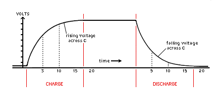
    I suggest to test with cap because we can have differnt values and are able to get damn short leads (5mm if possible).

    You connect your scope to driver output and GND.

    Vote this behaviour here as a microscopic view (time wise) to cap behaviour compared to normal charging desicharging caps at DC and mainsAC conditions. You can still apply the vision of filling a bottle at a water tap and pooring the bottle later on. But here the cavity is very small like the cavity at a ink jet printer - filling and poorinig pico-litre of fluid (pico = 10^-12).
    JS
    Last edited by JohnStone; 09-12-2013, 02:43 AM.
    Experts spend hours a day in order to question their doing while others stopped thinking feeling they were professionals.

    Comment


    • Originally posted by iankoglin View Post
      from post 2436

      @ Sampojo
      By moving the Opto up a bit then there was enough room to let the lands go between the legs of the Opto rather than having to add the 2 Jumpers.
      Also when making the inquiry ask if they can double up on the circuit with another layer a copy of the first in that way it is like adding extra solder
      Hi Kogs, Jim Neal at OSHPark said he would make it happen in August. Some boards got out single layer though. I should try to confirm that indeed the boards are doubled up. However, the only way a change to the board can be initiated would be for him to receive new gerber files.

      Originally posted by sampojo View Post
      from Post 2265
      Emailed Jim Neal, at laen@oshpark.com and he has already gotten 2 orders, YEH! International orders are NP! I believe OSHPark are out of Seattle WA.

      @KOGS asked about a double layer of traces, Mr always thinking guy, so I asked "laen" and he responded in a way that will make everyone more interested...

      Sampojo:
      Here is a good technical question a forum member has asked. Since you only make 2 layer boards as your lowest option, on our single layer board, when I duped out the appropriate file, does that mean you made a duplicate of the one layer of traces over again on the board in your automated processes? This would be great if so, as some members have reported some traces burning up due to the load on their home manufactured PCBs, using these gerber files on their equipment...

      -Laen
      I _can_ definitely do that. It sounds like that would be desirable, so I'll make it happen.
      Last edited by sampojo; 09-12-2013, 03:42 AM.
      Up, Up and Away

      Comment


      • Doohh, definately a newbie at this stuff.

        Here are some shots, all are done with exactly same settings on gen, First 3 are 10nf--20nf and Dana's 30nf,, then next is 30nf and last is 30nf.

        With my limited experience i would say this driver could easily handle 4 fets, but it may be different with a load under working conditions!

        Let me know what you think JS.

        Gotta go and set up my Extruder to cook a batch of soybeans now, but will keep checking in.

        Warm Regards cornboy.

        [IMG][/IMG]

        [IMG][/IMG]

        [IMG][/IMG]

        [IMG][/IMG]

        [IMG][/IMG]

        Comment


        • Hi All

          I asked in the Asymmetric Machines thread what the advantages are of pulsing the motors. Is it just to bring down input power and/or for recovering the field collapse of the coils?

          JohnStone said that there is no plain answer and pointed me to this thread.

          UFO states in the first post of this thread:

          However, my point in this thread is not about the discussion of this Motors, but, I will tell you that I use the Counter EMF completely on assistance of the rotation, not against [...].
          [...] Never needing to Reverse the Electromagnetic Fields Polarity in order to achieve rotation, the fields just Turn Off or Turn On according to the Oscillator Signals, and I achieve this, by the Coils Design inside of them. This design allows that at T-Off of the Square Wave (Circuit Opens) Rotor Idles, and keep going for nano seconds by inertia and the last magnetic interaction residues to the other Stator Pole where then is reversed "naturally" or by what The Physics call Back Electromotive Force, and this is How the C EMF Assist instead of "Oppose" to rotation.
          So, it seems to me now that turning the coils on and off is achieved by the asymmetrical architecture of the motor and not by a pulsing-circuit (like in the Bedini circuit)?

          The first pulse motor I learned about was the Bedini, so my knowledge of those motors is quite influenced by this principle. The Bedini circuit can remove the BEMF as well and allow for storing the energy (of the field collapse) in a secondary battery, so it does not oppose the rotation. Is this comparable to the principle of asymmetric machines?

          Regards

          adversarius

          Comment


          • Hello Adversarius, one thing to consider is that so far, all the machines we are working on, have mechanical switching as well as electronic pulsing, ie copper commutators and carbon brushes, so also a small spark gap, producing all sorts of frequency harmonics, is also involved.

            I have read that frequencies almost to infinity, can be available at a spark gap.

            Read up on Spark gap transmitters, to give some understanding.

            Warm Regards Cornboy.

            Comment


            • Originally posted by adversarius View Post
              Hi All

              I asked in the Asymmetric Machines thread what the advantages are of pulsing the motors. Is it just to bring down input power and/or for recovering the field collapse of the coils?

              JohnStone said that there is no plain answer and pointed me to this thread.

              UFO states in the first post of this thread:


              So, it seems to me now that turning the coils on and off is achieved by the asymmetrical architecture of the motor and not by a pulsing-circuit (like in the Bedini circuit)?

              The first pulse motor I learned about was the Bedini, so my knowledge of those motors is quite influenced by this principle. The Bedini circuit can remove the BEMF as well and allow for storing the energy (of the field collapse) in a secondary battery, so it does not oppose the rotation. Is this comparable to the principle of asymmetric machines?

              Regards

              adversarius
              There are several different schools of thought regarding Asymmetry in motors and generators. I'll skip that and go straight to the BEMF in the SG.

              When you look at the device the first thing you see is the all north poles out. This topology limits the amount of potential that the device will generate when spinning. The next thing to note is that during the BEMF moment, a pulse is applied which effectively turns the BEMF cycle into a forward EMF. The generator function within the SG is overridden by use of proper timed pulsing, and the unique magnet configuration in the rotor.

              It is my opinion that the SG has nothing in common with the machines under discussion in this thread.

              So in conclusion, the BEMF isn't being removed, and the collapsing field energy storage does have an effect on rotor speed, if the impedance isn't properly matched the speed is negatively affected.

              Hope that helps...

              @ Cornboy

              You will have much more control over harmonic mixing if you eliminate the spark gap (this includes commutators). The harmonic train you want is not a mix of all harmonics, it is specific wave train that you are looking for and it is directly related to the logarithmic spiral. The idea is to try and get those harmonics with abrupt changes in circuit conditions, however without the formation of plasma at the switch. My 2 cents.....

              Regards

              Comment


              • Originally posted by Cornboy 555 View Post
                ... Here are some shots, all are done with exactly same settings on gen, First 3 are 10nf--20nf and Dana's 30nf,, then next is 30nf and last is 30nf....
                [IMG][/IMG]
                This edge is even steeper than your first shot some days ago - as I understood without any load. ????
                We'd like to see results like above with (ascending / descending slope):
                • 0nF (*)
                • 10nF
                • 20nF
                • 30nF (*)
                • one real FET without gate resistor
                • both FETs without gate resistor (*)


                It is suffitient if you post values but pics will be OK as well. At least I would perform this way. But if it is too much effort for you, you might reduce to those test cases marked with (*)
                I will discuss results later on in order to get you all understand the procedure.

                BTW: My PCB were sent by Oshpark in August but might stay at customs some weeks.
                JS
                Experts spend hours a day in order to question their doing while others stopped thinking feeling they were professionals.

                Comment


                • Originally posted by erfinder View Post
                  [Regarding Bedini:] So in conclusion, the BEMF isn't being removed, and the collapsing field energy storage does have an effect on rotor speed, if the impedance isn't properly matched the speed is negatively affected.
                  I think we need to clarify what we mean with BEMF. According to this video (Understanding the Bedini Circuit - YouTube) the energy that is stored in the charging battery is not the BEMF, but "Flyback Voltage". But that term is made up by the video editor and probably everybody uses a different word for this voltage.

                  Regards

                  Comment


                  • soldering monster drives

                    @cornboy
                    I am asking you cornboy because you have accomplished what I am dreading. How difficult is soldering the pcbs? I have soldering irons and a soldering gun but you mention a soldering pump in one of your posts. Do I need special equipment to do this or is it possible with my 30 watt soldering irons or my weller soldering gun. I am truly intimidated by this part of the project and had wished to see a video on this technique. I know how to solder but my technique is crude and could use some polish for such a small area. Possibility of bridging seems highly likely.
                    @JS
                    Maybe you could video the population of the cornboy pcb. Just an idea for those of us that are new to this part of the project. I understand if you are unable to do so, I realize you have a very busy schedule.

                    Cheers

                    Garry

                    Comment


                    • Originally posted by GChilders View Post
                      @cornboy
                      I am asking you cornboy because you have accomplished what I am dreading. How difficult is soldering the pcbs? I have soldering irons and a soldering gun but you mention a soldering pump in one of your posts. Do I need special equipment to do this or is it possible with my 30 watt soldering irons or my weller soldering gun. I am truly intimidated by this part of the project and had wished to see a video on this technique. I know how to solder but my technique is crude and could use some polish for such a small area. Possibility of bridging seems highly likely.
                      @JS
                      Maybe you could video the population of the cornboy pcb. Just an idea for those of us that are new to this part of the project. I understand if you are unable to do so, I realize you have a very busy schedule.

                      Cheers

                      Garry
                      Hello Garry, i was dreading it too and KOGS picked up on my dread, and emailed me some soldering video's which were excellent.

                      I don't know how to link them here, maybe kogs could do that for you, i will email him and ask ok.

                      After watching the video i bought a soldering station, it cost $99.00 and has adjustable temp, and is digital, it is excellent, and sure helps you solder well, also i used sockets for all chips, so as not to heat them up.

                      Hope this helps, Cornboy.

                      Comment


                      • @ cornboy
                        Thanks for the quick reply. It puts my mind at ease. The price on the soldering station seems pretty reasonable. Could you send that info to me. Would appreciate it.

                        Cheers

                        Garry

                        Comment


                        • Hello Garry
                          Garry, anyone can do it but as the board and spacing is small, you could us a soldering station. The tips you have available with the Weller and regular pens are too fat and short. There is dozens of videos on you tube. Search for 'soldering Video' or Soldering Station' on you tube. Here is one tutorial video for starters.

                          Soldering Tutorial - YouTube

                          Dana
                          "Today's scientist have substituted mathematics for experiments and they wander off through equation after equation and eventually build a structure which has no relation to reality."
                          Nikola Tesla

                          Comment


                          • Garry
                            Get on ebay and type 'soldering station'. There are hundreds and many good ones with only one iron for even less. Get extra tips of the long thin type and make sure it comes with a sponge and sponge holder. These things make anybody an expert in five minutes.
                            Dana
                            "Today's scientist have substituted mathematics for experiments and they wander off through equation after equation and eventually build a structure which has no relation to reality."
                            Nikola Tesla

                            Comment


                            • What DANA said, Garry, just one thing, i ended up buying in Aus, because i needed 240v input, i don't know which country you are in, but i found on ebay a lot of soldering stations were 110v.

                              Mine is Mod ZD-981 from rhinotools.com.au and came with sponge and a spare pack of different tips.

                              Regards Cornboy.

                              Comment


                              • @Dana
                                Thanks for the info ordered a soldering station from Amazon.com for about 60.00 dollars us and a soldering pump. I think that I am ready when I get the pcbs. Thanks for the video. I have watched a few but my irons never seem to create a soldering joint as quickly and easily as the ones in the videos. Hope this solves the problem. The unit had a very high customer rating of 4.5 stars and for the money I think that is pretty good.

                                cheers

                                Garry

                                Comment

                                Working...
                                X