 Tweet
Tweet
Try this one...
Comme ces't va Monsieur Lerameur?
Please try this test:
[IMG]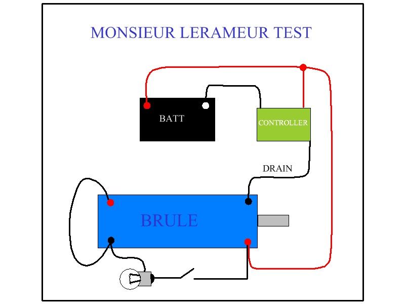 [/IMG]
Get the Oscillator or Controller to run motor at a pretty nice speed, not too much though...say a medium speed...then turn on the switch to light bulb ...
This is assuming you are using 12V Batteries...and the Bulb is a Car/Vehicle Incandescent type...12 Volts also...
I set a positive to controller, assuming you are feeding it from your batteries...but the main thing here are the Motor connections.
Watch/Record Motor Speed BEFORE and AFTER turning switch OFF/ON...with a Tachometer test would be much better...
Please, let Us know what happened...
Regards
Ufopolitics
Originally posted by lerameur
View Post

Please try this test:
[IMG]
 [/IMG]
Get the Oscillator or Controller to run motor at a pretty nice speed, not too much though...say a medium speed...then turn on the switch to light bulb ...
This is assuming you are using 12V Batteries...and the Bulb is a Car/Vehicle Incandescent type...12 Volts also...
I set a positive to controller, assuming you are feeding it from your batteries...but the main thing here are the Motor connections.
Watch/Record Motor Speed BEFORE and AFTER turning switch OFF/ON...with a Tachometer test would be much better...
Please, let Us know what happened...
Regards
Ufopolitics


 . But you took the chance to learn how a voltage regulator behaves if its GND pin is floating. You never will forget it


Comment