Announcement

Collapse
No announcement yet.

My Motors got me to Tap into Radiant Energy

Collapse
X
 
  • Filter
  • Time
  • Show
Clear All
new posts

  • MOSFET question

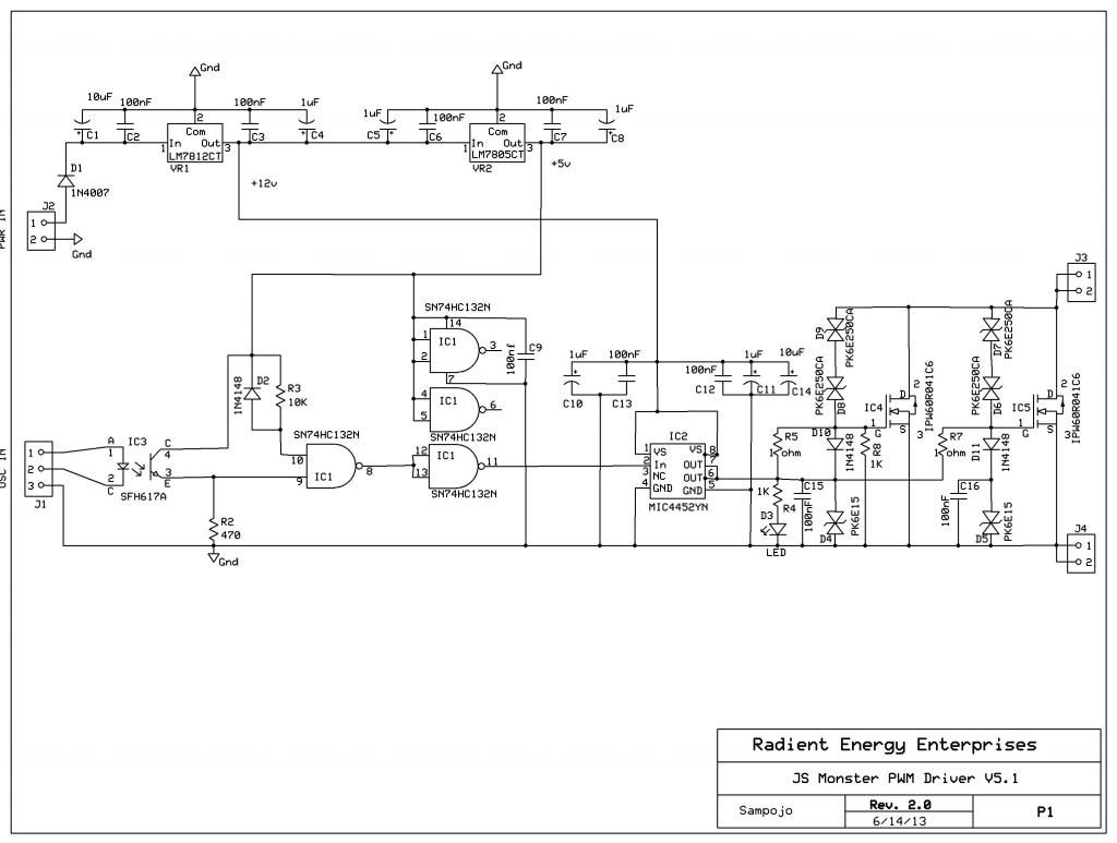
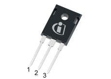
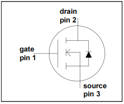
    Assembling my OSHpark Monser driver v5.1 boards finally. On the MOSFET, Pin 1 is the gate, Pin 2 the drain and Pin 3 the source. What I am seeing seems a little counter intuitive, is that the "source" pin is hooked up to the board and battery ground then? Is my understanding correct? Here are the diagrams.
    Schematic: (Note: R2 value is incorrect, has been changed to 330)

    (This is now the corrected image, using blogspot instead of photobucket)


    Package diagram


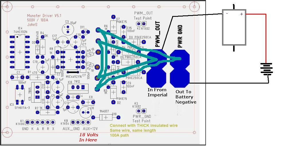
    Piece schematic

    Using 1 ohm on R3,8 Edit: Sorry, threw up my old express PCB schematic, not numbered the same as JS T3001 schematic. It is R7,8 on this diagram and R3,9 on the JS schematic

    Any input appreciated
    Last edited by sampojo; 09-12-2019, 03:52 PM.
    Up, Up and Away

    Comment


    • Originally posted by sampojo View Post
      Assembling my OSHpark Monser driver v5.1 boards finally. On the MOSFET, Pin 1 is the gate, Pin 2 the drain and Pin 3 the source. What I am seeing seems a little counter intuitive, is that the "source" pin is hooked up to the board and battery ground then? Is my understanding correct? Here are the diagrams.
      Schematic: (Note: R2 value is incorrect, has been changed to 330)


      Package diagram


      Piece schematic


      Using 1 ohm on R3,8

      Any input appreciated


      Hey Joey, that is correct, source to battery negative, drain to - end of motor coils.

      You are simply using these boards as an on/off switch on the low side, or negative side, completing the circuit.

      Great to see you building these now.

      Regards Friend, Cornboy.

      Comment


      • PKE250CA transil diode problem on Monster driver

        My mouser part from Fairchild does not have a color band on the part to denote the cathode. The datasheet diagram says its supposed to. Can't just hook up a multimeter to see which way the current goes on these. Its says bidirectional. Does that mean it doesn't matter which way it goes?

        Any body know a way to tell which side is the cathode on these?

        RE post on MOSFETs, thanks cornboy! and thx! Very informative.
        Last edited by sampojo; 07-16-2014, 09:53 PM.
        Up, Up and Away

        Comment


        • Ground heatsinks for MOSFETs?

          Should the heats sinks for the MOSFETs on Monster driver be grounded to board ground?
          Up, Up and Away

          Comment


          • Originally posted by sampojo View Post
            My mouser part from Fairchild does not have a color band on the part to denote the cathode. The datasheet diagram says its supposed to. Can't just hook up a multimeter to see which way the current goes on these. Its says bidirectional. Does that mean it doesn't matter which way it goes?

            Any body know a way to tell which side is the cathode on these?

            RE post on MOSFETs, thanks cornboy! and thx! Very informative.
            G'day Sampojo
            Bidirectional means just that you do not need to worry about polarity
            With regard to the diodes that are polarized you will notice that they have a stripe around the circumference one end and if they come taped together the tape on this leg is red colour this is the cathode end the striped end


            The back of the Mosfets is also connected to the centre pin the Drain which when connected to the heat sink, and this is connected to the negative of the Motor
            I hope this helps
            Last edited by iankoglin; 07-17-2014, 11:38 PM. Reason: Correction

            Comment


            • thanks Kogs! conductive grease anyone?

              Originally posted by iankoglin View Post
              G'day Sampojo
              Bidirectional means just that you do not need to worry about polarity
              With regard to the diodes that are polarized you will notice that they have a stripe around the circumference one end and if they come taped together the tape on this leg is red colour this is the cathode end the striped end


              The back of the Mosfets is also connected to the centre pin the Drain which when connected to the heat sink, and this is connected to the negative of the battery

              I hope this helps
              Kogs, thanks a million! so cool to have a show-stopper problem when you go to sleep at night and have blokes on the other side of the world answer the question for you when you wake up in the AM!

              Heres another worry wort problem, can't find my electronic heat conductive grease anywhere but would like to use it on the heat sink, but am concerned it may affect electronic conductivity on the ground connection of the heat sink. Better off grounding it independently then?
              Last edited by sampojo; 07-17-2014, 12:55 PM.
              Up, Up and Away

              Comment


              • Drain To Negative of Battery?!

                Originally posted by iankoglin View Post

                The back of the Mosfets is also connected to the centre pin the Drain which when connected to the heat sink, and this is connected to the negative of the battery


                Hello my Dear Friend Kogs,

                I believe the above statement tends to confusion...or am I wrong?

                The Drain of the MOSFET should go to the Negative Input of Motor, and Not to the Negative of Battery...am I right?

                Negative from Battery should go to Source of the FET.


                Kind Regards


                Ufopolitics
                Principles for the Development of a Complete Mind: Study the science of art. Study the art of science. Develop your senses- especially learn how to see. Realize that everything connects to everything else.― Leonardo da Vinci

                Comment


                • If...

                  Originally posted by sampojo View Post
                  Kogs, thanks a million! so cool to have a show-stopper problem when you go to sleep at night and have blokes on the other side of the world answer the question for you when you wake up in the AM!

                  Heres another worry wort problem, can't find my electronic heat conductive grease anywhere but would like to use it on the heat sink, but am concerned it may affect electronic conductivity on the ground connection of the heat sink. Better off grounding it independently then?
                  Hello Sam,

                  If the Heat Sink is supposed to be attached to Ground, and Ground goes to Battery Negative...Then you need to Isolate the Heat Sink from the Drain Contact through the Mica/Bakelite transparent sheets as also a washer/nut that is made of heat resistive plastic for the bolt/nut not to make contact with FET's Drain Plate...Only then you could use the Heat Grease based on White Silicon Compound which is not conductive electrically, only transfers heat.

                  That is my opinion, however, I have to check again the Monster Driver Diagrams

                  Regards Sam

                  Ufopolitics
                  Principles for the Development of a Complete Mind: Study the science of art. Study the art of science. Develop your senses- especially learn how to see. Realize that everything connects to everything else.― Leonardo da Vinci

                  Comment


                  • Originally posted by iankoglin View Post
                    G'day Sampojo
                    Bidirectional means just that you do not need to worry about polarity
                    With regard to the diodes that are polarized you will notice that they have a stripe around the circumference one end and if they come taped together the tape on this leg is red colour this is the cathode end the striped end


                    The back of the Mosfets is also connected to the centre pin the Drain which when connected to the heat sink, and this is connected to the negative of the Motor
                    I hope this helps
                    G'day UFO, Sampojo and all others
                    I wrote the above in a hurry and did not proof read it
                    UFO I am glad you noticed my error and I have corrected the above post

                    So as to stop any confusion I will delete this Post in a few Days

                    Kindest Regards

                    Kogs has never ever made even one mistake Just 100's of errors and still going

                    Comment


                    • Originally posted by Ufopolitics View Post
                      Hello Sam,

                      If the Heat Sink is supposed to be attached to Ground, and Ground goes to Battery Negative...Then you need to Isolate the Heat Sink from the Drain Contact through the Mica/Bakelite transparent sheets as also a washer/nut that is made of heat resistive plastic for the bolt/nut not to make contact with FET's Drain Plate...Only then you could use the Heat Grease based on White Silicon Compound which is not conductive electrically, only transfers heat.

                      That is my opinion, however, I have to check again the Monster Driver Diagrams

                      Regards Sam

                      Ufopolitics
                      G'day UFO and Sampojo
                      I corrected my post above

                      The back of the Mosfets is also connected to the centre pin the Drain which when connected to the heat sink, and this is connected to the negative of the Motor

                      Kindest Regards

                      Kogs a bit

                      Comment


                      • Originally posted by Ufopolitics View Post
                        Hello my Dear Friend Kogs,

                        I believe the above statement tends to confusion...or am I wrong?

                        The Drain of the MOSFET should go to the Negative Input of Motor, and Not to the Negative of Battery...am I right?

                        Negative from Battery should go to Source of the FET.


                        Kind Regards


                        Ufopolitics
                        G'day UFO
                        You are Right The back of the Mosfets is also connected to the centre pin the Drain which when connected to the heat sink, and this is connected to the negative of the Motor


                        Thanks for picking up my error I should proof read before pushing the submit button

                        Thanks my friend

                        Comment


                        • Heat sink ology

                          Originally posted by Ufopolitics View Post
                          Hello Sam,

                          If the Heat Sink is supposed to be attached to Ground, and Ground goes to Battery Negative...Then you need to Isolate the Heat Sink from the Drain Contact through the Mica/Bakelite transparent sheets as also a washer/nut that is made of heat resistive plastic for the bolt/nut not to make contact with FET's Drain Plate...Only then you could use the Heat Grease based on White Silicon Compound which is not conductive electrically, only transfers heat.

                          That is my opinion, however, I have to check again the Monster Driver Diagrams

                          Regards Sam

                          Ufopolitics
                          hmm... So yeah the center pin goes to the drain and to the heat sink and to the negative on the motor, not battery ground. I guess grounding means grounding to battery ground and would be optimal. So mica insulators would be good. Got some pads from the salvaged heat sinks that must do just this job! only 2 though, good for only 1 board, but I at least know what to look for now.

                          I am tempted to leave them floating and ungrounded but I bet that's a bad idea. Or even attached directly to Drain without an insulator. Again probably a bad idea. I wonder what Dana did?
                          Up, Up and Away

                          Comment


                          • Adding in the heavy wires on the MOSFETs

                            looking at using 12 or 14ga solid house wires on the light blue connections here...


                            I am supposing I should use 12 rather than 14, but I know it will take a lot more heat to solder, worrying about the components. Guess I can put some more heat sinking action on it like a small damp cloth...

                            Would 12ga be enough for an Imperial style operation taking 12-18A?
                            Up, Up and Away

                            Comment


                            • Originally posted by sampojo View Post
                              looking at using 12 or 14ga solid house wires on the light blue connections here...


                              I am supposing I should use 12 rather than 14, but I know it will take a lot more heat to solder, worrying about the components. Guess I can put some more heat sinking action on it like a small damp cloth...

                              Would 12ga be enough for an Imperial style operation taking 12-18A?
                              G'day Sam

                              Please do not use insulation pads as you can connect this way better


                              The cables I am using are Jaycar 12 Gauge OTC High current Power current
                              it has more very fine wires for Solar and DC operations solder the 12G to the ground as I have shown the solder is about 2mm thick do this before any other components


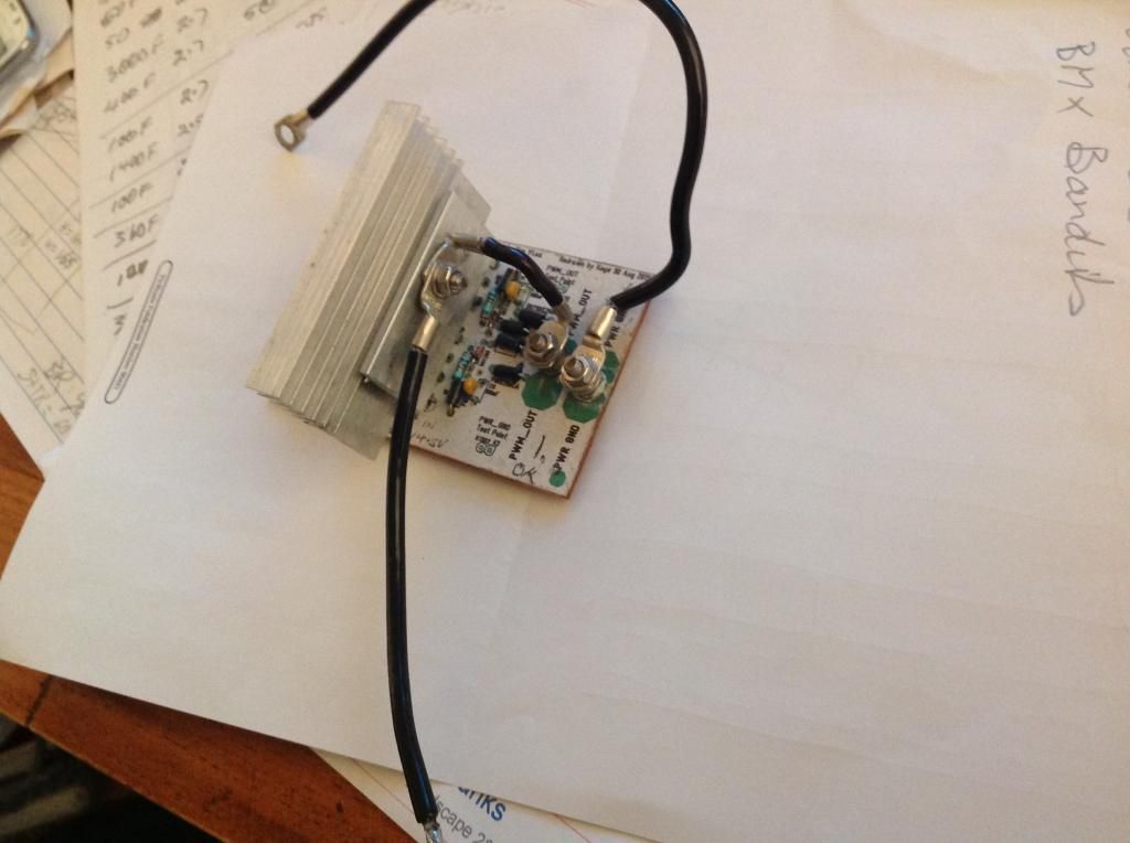
                              Firstly before inserting any components solder a heavy layer onto the pads where the bolts go through the pads probably 2mm thick then solder some 12G from where the source pins come out.
                              Use 3mm diam. countersink headed bolts then countersink for the bolt heads and use Heat sink paste when fitting the c/s bolts and use a washer and nut and tighten hard when this is done solder the other components in and when you gave soldered them you can cut off the centre pin the drain pin from the Mosfet as you are connecting through the back into the heat sinks the heat sinks 2 of them are fitted with heat sink paste on both sides of the Mosfets and bolted with 2 - 3mm screws drilled and tapped to secure them together and press them against the Mosfets and there is a bolt that goes between the Mosfets countersunk in one and secured using heat sink paste and the nuts tightened securely

                              The Heat sink paste is necessary anywhere there is a connection to the heat sink as this makes a proper electrical connection

                              You notice the 12G going from the Power out to the Heat sink you need to bend this first and measure/determine where the solder cable connector goes band bend into shape before soldering as the soldering makes this wire stiff


                              Any questions please ask

                              Kogs just trying to be helpful

                              Comment


                              • Kogs, most helpful indeed

                                Looks very well engineered! So you use the heatsink as the best connection point. I already have the center pin in place, no harm I suppose. putting some heatsink SILVER compound on order! I suppose I could beef up that connection a little too. Going with some stranded wire and filling up those pads with solder!

                                thanks Kogs
                                Up, Up and Away

                                Comment

                                Working...
                                X