Announcement

Collapse
No announcement yet.

My Motors got me to Tap into Radiant Energy

Collapse
X
 
  • Filter
  • Time
  • Show
Clear All
new posts

  • #46
    Originally posted by Aaron View Post
    I just saw this: RADIANT FREE ENERGY - YouTube

    Not sure if this is part 2: http://www.youtube.com/watch?v=XyTRX8IfJQY but youtube removed it for music copyright violation. Looking forward to seeing it.
    No, that is Not it...I always put names to my videos sequences...This series are "RADIANT FREE ENERGY"
    That is a dispute I am having with YT because I use Money from Pink Floyd (EMI Rights)...When J.P Morgan decides to take down Nikola Tesla patent on wireless transmission of electricity...
    But is Ok...I just did not have the time but I could load videos on my private servers...and post them anywhere...
    Second part has not come out yet...hehe...stay tuned.

    Thanks
    Principles for the Development of a Complete Mind: Study the science of art. Study the art of science. Develop your senses- especially learn how to see. Realize that everything connects to everything else.― Leonardo da Vinci

    Comment


    • #47
      Quote from Aaron - With a transistor, you can guarantee that the only path is to the load on the "cold" side when it is switched off.
      I concur and my test show me the same. However, I didn't run any test with Mosfet yet. Need to tutor myself to understand this animal better
      I was also running small DC motor from it and didn't notice any return path but again, I used bipolar transistor only. I should have some but need to check online what they're. I also agree on fast diodes. Didn't found them yet. I remember same issues while working with Tesla Switch. I couldn't get expected results until replacing them. Thank you Ufopolitics for sharing. I only have one "energy efficient" spiral bulb left in the house. It is rated 13W. I removed them while ago due to the Hg content.

      Thanks
      Vtech
      Last edited by blackchisel97; 02-08-2012, 09:05 PM. Reason: edit
      'Get it all on record now - get the films - get the witnesses -because somewhere down the road of history some bastard will get up and say that this never happened'

      General D.Eisenhower


      http://www.nvtronics.org

      Comment


      • #48
        Originally posted by Farmhand View Post
        Looks like your harvesting the collapsing magnetic field to me.

        How do you say your not just using the emf from the collapsing magnetic field ?
        It is very simple to answer that with just two facts:

        Number one, I have measured what you call Back EMF, or C EMF due to the "Collapsing Magnetic Field" (And I understand perfectly your statements in their entirety. As it is the way Physics had explained it, and the way WE have learned for many generations )

        Now, out of the "Box" of Physics, just for a few seconds if you could...just let be, your self common sense judgement in complete control...

        Does a "Collapsing Magnetic Field" shows this type of "Attitude"??

        1- Does a Collapsing Magnetic Field gives you readings of much higher Increase of Operating Frequencies (Hz) than the Originating (Our) Magnetic Field, under constant oscillations coming from "our side"?

        2-Does a Collapsing Magnetic Field, where you have previously and clearly defined your Originating Magnetic Field polarities, changes into an Opposite Polarity that is Much Greater in Strength, to the point of Turning upside down a Rare Earth, super strong cylindrical permanent magnet, in order to attract to that supposedly collapsing magnetic field opposite pole?

        I have done this tests...and , by all means, you are free to go ahead and try them also.


        Thanks so much, Farmhand, for bringing the Issue I was expecting for...even though I had mentioned so many times here...

        Regards

        Ufopolitics
        Principles for the Development of a Complete Mind: Study the science of art. Study the art of science. Develop your senses- especially learn how to see. Realize that everything connects to everything else.― Leonardo da Vinci

        Comment


        • #49
          Originally posted by Aaron View Post
          I'm not trapped in anything. You're preaching to the choir here so don't get me wrong. I'm just asking for clarification.

          Your red arrow looks like it simply shows the direction of the positive voltage potential while the "hot current" actually moves in the opposite direction of the red arrow on that side of the circuit. But I understand
          your point that it is on the "hot" side.

          In this diagram, as mentioned earlier, the power supply is reversed. Is that intentional and you're trying to run the circuit inverted or something?


          Or is the power supply actually supposed to have the positive terminal connected directly to the inductor like this:


          I apologize if you already answered that but its a bit confusing to show both because their operation would be different.

          No, I am looking at both sides. I said the spike from inductor moving to source battery will do so if it is unloaded on the "cold" side. That is a fact that you seem to agree with and this has nothing to do with the "cold" side. And this only happens with a mosfet that has the internally reversed didoe and will not do this with a transistor.

          There was a diagram early in this thread showing it can be a transistor or a mosfet but if the circuit is unloaded, they behave differently. When the transistor is off, the inductor does not kick back to the battery - I have never seen this, not even a $10k scope could find any kickback to the primary battery.

          Mosfet is a different story of course. When the mosfet is off, the intrinsic diode is in the reverse direction so the cathode is at the inductor side of the mosfet and it will be in full conduction so the coil's collapse does have a path back to the front battery. You probably know this, but I'm just spelling it out so there it is clear what I'm saying.

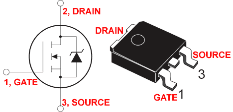
          Here is a diagram for anyone unfamiliar with this - almost all mosfets have this reversed diode in it from source towards gate back towards the positive of the power supply:


          Does your mosfet have the reversed diode or not? I know it doesn't make a difference in your overall example, but I think it is helpful to know specifically.

          And I said that IF the other side IS loaded, then a difference may be seen on the primary battery by putting a scope across it. I just said there can be a comparison that can be seen to demonstrate where the spike is preferring to go. Obviously if the impedance of the load on the "cold side" is less than the impedance of the inductor, the spike will take that route and nothing will be pulsed back to the primary.

          So based on your diagram, if you put a low impedance battery there on the output on the "cold side", the battery of course will receive the spike and it will charge it. But if you put an inductor on that output side and it is a higher impedance than the coil on the mostfet, that spike will never go to the load, it will go back to the battery - if the mosfet has the reversed diode in it that is.

          With a transistor, you can guarantee that the only path is to the load on the "cold" side when it is switched off.

          Anyway, I'm not disputing your claims about what happens on the "cold" side - this is all for clarification.

          So far, do you agree with all the above? This doesn't get to what happens on the "cold" side yet but I think helps set the stage - at least for me to understand what you're doing.
          Hello Aaron,

          In My first Diagram I admitted I was wrong relating to the Battery Polarity set up...and Blackchisel fixed for me an even had the great help of replacing my regular transistor symbol by one of an N-Channel MOSFET...Anyways, that transistor I blew it up,and since was not a MOSFET, by inverting the terminals...didn't have the intrinsic diode... So yes Blackchisel, go ahead and throw it out, no good anymore...

          In any of my circuits I am including a "Second Battery"...that kind of set up developed by comparing Mr. Bedini's charging circuit to mine...but all my batteries are charged so far...and I do not need to charge them at least for now...

          And yes, I do know about the intrinsic diode on MOSFET's...in my circuits I always use an extra one right next to each MOSFET's of the Parallel Bank, since they are not as strong as a dedicated component specifically for those reasons...

          The real way electricity flows is through electrons displacement...The term Positive or Negative is 'relative', but saying it more 'generally'...they move to where there is "Lack or Less" Electrons from areas where there is excess of them, "Positive Side", results in Holes, attraction to electrons, and since earlier years it was defined with a Cross...and a point to the negative side...Now we have changed those symbols a bit..but originally they found it an easier way like looking at an Arrow...From back end (+) or coming towards you (.)
          Then in newer times and Up to Now, they had shown the Flow to be from positive to negative...with a red arrow-line...and named Positive as "Source", as Provider, as Feeder...and Negative as a Drain, an Absorption, a Sink...However, I agree with you, Aaron, that this New Terminology is completely wrong, therefore confusing, but if we know how it really works...and have our 'concepts very solid and clear'...this changes would not affect Us, nor make a big of a deal ...

          Regards

          Ufopolitics
          Principles for the Development of a Complete Mind: Study the science of art. Study the art of science. Develop your senses- especially learn how to see. Realize that everything connects to everything else.― Leonardo da Vinci

          Comment


          • #50
            2 Tests

            2 Tests if you will...
            Test #1
            If this is truly cold current you should be able to run it through a resistive load and the resistor should cool down.

            Test #2
            Measure the resistance of the WATER you submersed the bulb hookups in at or about the same distance as the lamps hookup. Measure the current going into the bulb and coming out of the bulb and calculate the resistance through the ballast. This should tell you the amount of resistance (roughly) as compared to the water.

            And while your at it hook the leads up to your wet finger and see if the charge penetrates your skin or if rides the surface.

            If the resistor cools down and the water has low to no resistance (and you didn't get shocked) then you are dealing with some form of cold current.

            Other wise your just looking at high frequency high voltage, with little to no current.

            Matt

            Comment


            • #51
              Originally posted by Dave45 View Post
              @Ufopolitics
              please dont get discouraged with some here, we are just trying to understand
              please continue with your findings
              dave
              Hey Dave,

              Thanks my friend for your nice words...I am not discouraged or EVER BE, my friend...I am very POSITIVE and SO SURE of what am saying, writing, stating and claiming, that you may have no idea how much...
              I have been around for too long when some were not even born yet...but I had Children also...and I understand them...

              Cheers

              Ufopolitics
              Principles for the Development of a Complete Mind: Study the science of art. Study the art of science. Develop your senses- especially learn how to see. Realize that everything connects to everything else.― Leonardo da Vinci

              Comment


              • #52
                This reminds me of Sparky Sweets VTA he got massive cold electricity
                Half of the Answer is knowing the right Question

                Comment


                • #53
                  Originally posted by Matthew Jones View Post
                  So about 8 years ago I built this very same motor on my own. I used a set of points, transistors, Fets, relays, all kinds of switch's. Simple Motor
                  It just interests me how it someone else rediscovered.

                  So instead of complaining or anything let me give some assets, so you read further into what you are doing. It is a very conventionally used circiut.

                  Boost converter - Wikipedia, the free encyclopedia

                  John Bedini's patent

                  And there is one other link for a patent from Toyota back in the 70's, but it evaids at the moment.

                  The joule thief's all work this way.

                  You just stepping up voltage. You may be harvesting the collapsing field to some extent but if your stepping the voltage up more than about 8x via the boost circuit, what your seeing is ultra low current voltage. Not much else. Even at those ratio's the BEMF is very low and will be indicated by the negative curve on your scope. You also maybe seeing transient behavior from the inductor. This is real extra energy, but the net gain will not get you above 99% as you have to tap the ground to make the current move, to create the effect. Most boost circuits reside in the 89%- 92% percent ratio for efficiency.
                  If you take the time to scope it with some math you'll find your efficiency.

                  Now that is not to say its not useful, but there are better means to go about the process. Search this forum, a few people have found them.

                  Matt

                  Hello Mathew,...How are you?
                  I am fine thanks

                  Well congratulations Mathew, about your motors!
                  So it seems you also like to built your own things, that's great...
                  I also like to build things...and you know what?...whenever no one makes a type of structure in any type of material...I build-mold it, shape it, from scratch...whether Stainless or regular Steel, Aluminum etc...Plasma cut it, MIG Weld it , TIG Weld it , lathe them...or when I use Cold Composites like Carbon Fiber, Kevlar, Fiber Glass then I use nice Resins to mold them like Epoxies...Polyesters,etc...I mean the works...but first, of course I set the designs in Auto CAD...then make prototypes in 3D and Animate them...I master a few of this nice programs...Like MAYA, Studio MAX, etc....and of course even make the editing also...Adobes are great programs for those things...like After Effects..Premiere or to just "touch'em up" with Photo Shop...
                  However I also build my electronic circuits, love to do that!...from scratch..no need to Bread Boards...too "thick"..and people in videos may think you are "Tricking" something, some wires running under the plastic...so they say is just a Hoax, Scams etc...and some daring ones call me even "Thief"...¿Could You believe that Matt?
                  But I bet You are also a builder just like me, I see it in the ways you express yourself.

                  Now, related to the Boost Converter...yes I do know them very well...for very long...and then some ..
                  They belong within the Buck Booster Converters Family...However this one you are showing is the least complex of all of them...
                  The SEPIC, the CÚK and ZETA...which are actually a bit more complicated than this Booster Type, just because they "Pump" from two Inductors instead of just One, kind of a "Push-Pull" arrangement design...

                  And related to Bedini's patent, many other members here already brought those issues and I explained the differences to them...

                  But I do not think you have got the time to go over all the comments yet...

                  Thanks

                  Ufopolitics
                  Principles for the Development of a Complete Mind: Study the science of art. Study the art of science. Develop your senses- especially learn how to see. Realize that everything connects to everything else.― Leonardo da Vinci

                  Comment


                  • #54
                    bypass diode

                    Originally posted by Ufopolitics View Post
                    Anyways, that transistor I blew it up,and since was not a MOSFET, by inverting the terminals...didn't have the intrinsic diode... So yes Blackchisel, go ahead and throw it out, no good anymore...

                    And yes, I do know about the intrinsic diode on MOSFET's...in my circuits I always use an extra one right next to each MOSFET's of the Parallel Bank, since they are not as strong as a dedicated component specifically for those reasons..
                    Thanks, got it.

                    I've never had a good experience with the reverse "free-wheeling" diodes in the mosfets - seem like junk - they're slow and clunky. In my inductive resistor tests, I wound up bypassing that diode (just putting the diode in parallel with the mosfet - anode to source and cathode to drain) with my own preference of high speed diodes and was able to drop the power requirement for the same work by 1/3 up to 2/3! I expected to see a difference but didn't know it was that big of a difference. That was specifically to shuttle the spike right back to the input source as that was the point in those experiments. Anyway, just goes to show the the amount of work done is not related to the amount of magnetism.

                    I'll look forward to your vids.
                    Sincerely,
                    Aaron Murakami

                    Books & Videos https://emediapress.com
                    Conference http://energyscienceconference.com
                    RPX & MWO http://vril.io

                    Comment


                    • #55
                      [QUOTE]
                      Originally posted by Ufopolitics View Post
                      It is very simple to answer that with just two facts:

                      Number one, I have measured what you call Back EMF, or C EMF due to the "Collapsing Magnetic Field" (And I understand perfectly your statements in their entirety. As it is the way Physics had explained it, and the way WE have learned for many generations )

                      Now, out of the "Box" of Physics, just for a few seconds if you could...just let be, your self common sense judgement in complete control...

                      Does a "Collapsing Magnetic Field" shows this type of "Attitude"??

                      1- Does a Collapsing Magnetic Field gives you readings of much higher Increase of Operating Frequencies (Hz) than the Originating (Our) Magnetic Field, under constant oscillations coming from "our side"?

                      2-Does a Collapsing Magnetic Field, where you have previously and clearly defined your Originating Magnetic Field polarities, changes into an Opposite Polarity that is Much Greater in Strength, to the point of Turning upside down a Rare Earth, super strong cylindrical permanent magnet, in order to attract to that supposedly collapsing magnetic field opposite pole?

                      I have done this tests...and , by all means, you are free to go ahead and try them also.


                      Thanks so much, Farmhand, for bringing the Issue I was expecting for...even though I had mentioned so many times here...

                      Regards

                      Ufopolitics
                      Hi Ufopolitics, Firstly I'm not referring to the collapsing magnetic field as back
                      emf, I am referring to the collapsing magnetic field as emf, that is forward emf.
                      It must be forward emf because it is producing force in the same direction as
                      the applied emf.

                      Could you show what you call the measurement of back emf ?

                      To answer your questions.

                      1- Does a Collapsing Magnetic Field gives you readings of much higher Increase of Operating Frequencies (Hz) than the Originating (Our) Magnetic Field, under constant oscillations coming from "our side"?
                      It depends. Possibly it could if the load caused it. Can you show this increased frequency as
                      compared to the input frequency ? If you can then show it don't just say it.

                      2-Does a Collapsing Magnetic Field, where you have previously and clearly defined your Originating Magnetic Field polarities, changes into an Opposite Polarity that is Much Greater in Strength, to the point of Turning upside down a Rare Earth, super strong cylindrical permanent magnet, in order to attract to that supposedly collapsing magnetic field opposite pole?
                      I'm not the one making the claims here, I can't really picture what you are
                      saying in this second question. Can you show this by demonstration ? The
                      collapsing magnetic field can produce very high voltages as compared to the
                      input.

                      In the video i'll link below at 6:10 mins you can see the collapsing field energy can
                      charge a 470 uf capacitor to over 40 volts almost instantly even though the
                      source voltage is only 12 volts, which is normal, the coil used has not got a
                      lot of turns, if it had more turns the voltage would be higher still. And it
                      continues to climb because the voltage is relevant to the resistance of the
                      discharge path, to a degree.

                      A collapsing magnetic field of an inductor produces emf in the same direction
                      as the applied emf, it's really that simple.

                      I repeat what you are utilizing when you use the energy from the collapsing
                      magnetic field is normal forward emf. That was my only contention.

                      How can you say you are using back emf ?

                      Also in this video between 2:00 mins and 3:00 mins you can see that utilizing
                      the emf from the collapsing magnetic field reduces the magnetizing force
                      produced by the coil. Which makes sense to me.

                      Big relay.wmv - YouTube

                      Also it's the frequency that makes it not dangerous not it's temperature. I can
                      touch the 24 Khz output at 380 volts from my converter and feel only a fast
                      vibration, it is a surprise when it's touched but it doesn't kill because of the
                      frequency, the converter can supply 100's of watts, I still wouldn't say it was
                      harmless. Water has quite high resistance as well unless it's salty. Try the
                      experiment with a saturated saline solution.

                      Besides the CFL is receiving the pulsed DC current through a FWBR and
                      storing it in a capacitor then inverting the charge it stored in the capacitor
                      into HF HV AC to run the CFL. The nature of the current you provide it is
                      completely changed, before the CFL utilizes your provided input it is stored as
                      DC in a capacitor, then the CFL circuitry converts it to what it uses to
                      illuminate the tube. I suspect this is why you do not fully immerse the
                      circuitry of the CFL in the water, It would destroy the CFL circuitry.
                      The CFL circuitry usually contains a small transformer so the emf the CFL uses
                      is provided by the small transformer in the CFl circuitry.

                      Cheers
                      Last edited by Farmhand; 02-09-2012, 12:02 AM.

                      Comment


                      • #56
                        Originally posted by Matthew Jones View Post
                        2 Tests if you will...
                        Test #1
                        If this is truly cold current you should be able to run it through a resistive load and the resistor should cool down.

                        Test #2
                        Measure the resistance of the WATER you submersed the bulb hookups in at or about the same distance as the lamps hookup. Measure the current going into the bulb and coming out of the bulb and calculate the resistance through the ballast. This should tell you the amount of resistance (roughly) as compared to the water.

                        And while your at it hook the leads up to your wet finger and see if the charge penetrates your skin or if rides the surface.

                        If the resistor cools down and the water has low to no resistance (and you didn't get shocked) then you are dealing with some form of cold current.

                        Other wise your just looking at high frequency high voltage, with little to no current.

                        Matt
                        Matt,

                        Have you seen my video?
                        Have you read my posts here?
                        Have You read all comments here?
                        Have you read my main post entirely?


                        I do not think so.

                        Or are you evaluating-judging me somehow, because right next to Ufopolitics, on this Forum, it reads "Junior Member"??

                        "...And while your at it hook the leads up to your wet finger and see if the charge penetrates your skin or if rides the surface..."
                        Over my "Lifetime" , I have got shocked with 120 V AC Live wires and wet or grounded many times, as I have done many electrical work with AC...I know the difference.

                        "...Other wise your just looking at high frequency high voltage, with little to no current..."
                        Little or no current?...Do you think I do not have equipments?...that I am ignoring Amperage read outs here?

                        Matt, May I ask you...¿How do you know exactly the patterns, spec´s and behavior of Cold Electricity or Radiant Energy to that extent ?

                        Are they also explained in Wikipedia?

                        Wikipedia's answer: "The page "Cold Electricity" does not exist. You can ask for it to be created, but consider checking the search results below to see whether the topic is already covered..."

                        I have read many Inventors Matt, and some besides, been also great writers like Mr. Peter Lindemann...which great articles and Videos I love...Along with many others like Tom Bearden, Edwin Gray, I mean many...not to say all

                        ¿Have You Matt?

                        Regards

                        Ufopolitics

                        P.D: I know inverse question mark are not used in English Language Grammar, but since I speak fluently others...I tend to "mix" them on my keyboard.
                        Principles for the Development of a Complete Mind: Study the science of art. Study the art of science. Develop your senses- especially learn how to see. Realize that everything connects to everything else.― Leonardo da Vinci

                        Comment


                        • #57
                          [QUOTE=Farmhand;179210]

                          Hi Ufopolitics, Firstly I'm not referring to the collapsing magnetic field as back
                          emf, I am referring to the collapsing magnetic field as emf, that is forward emf.
                          It must be forward emf because it is producing force in the same direction as
                          the applied emf.

                          Could you show what you call the measurement of back emf ?

                          To answer your questions.


                          It depends. Possibly it could if the load caused it. Can you show this increased frequency as
                          compared to the input frequency ? If you can then show it don't just say it.


                          I'm not the one making the claims here, I can't really picture what you are
                          saying in this second question. Can you show this by demonstration ? The
                          collapsing magnetic field can produce very high voltages as compared to the
                          input.

                          In the video i'll link below at 6:10 mins you can see the collapsing field energy can
                          charge a 470 uf capacitor to over 40 volts almost instantly even though the
                          source voltage is only 12 volts, which is normal, the coil used has not got a
                          lot of turns, if it had more turns the voltage would be higher still. And it
                          continues to climb because the voltage is relevant to the resistance of the
                          discharge path, to a degree.

                          A collapsing magnetic field of an inductor produces emf in the same direction
                          as the applied emf, it's really that simple.

                          I repeat what you are utilizing when you use the energy from the collapsing
                          magnetic field is normal forward emf. That was my only contention.

                          How can you say you are using back emf ?

                          Also in this video between 2:00 mins and 3:00 mins you can see that utilizing
                          the emf from the collapsing magnetic field reduces the magnetizing force
                          produced by the coil. Which makes sense to me.

                          Big relay.wmv - YouTube

                          Also it's the frequency that makes it not dangerous not it's temperature. I can
                          touch the 24 Khz output at 380 volts from my converter and feel only a fast
                          vibration, it is a surprise when it's touched but it doesn't kill because of the
                          frequency, the converter can supply 100's of watts, I still wouldn't say it was
                          harmless. Water has quite high resistance as well unless it's salty. Try the
                          experiment with a saturated saline solution.

                          Besides the CFL is receiving the pulsed DC current through a FWBR and
                          storing it in a capacitor then inverting the charge it stored in the capacitor
                          into HF HV AC to run the CFL. The nature of the current you provide it is
                          completely changed, before the CFL utilizes your provided input it is stored as
                          DC in a capacitor, then the CFL circuitry converts it to what it uses to
                          illuminate the tube. I suspect this is why you do not fully immerse the
                          circuitry of the CFL in the water, It would destroy the CFL circuitry.
                          The CFL circuitry usually contains a small transformer so the emf the CFL uses
                          is provided by the small transformer in the CFl circuitry.

                          Cheers


                          Hey Farmhand,

                          Ok, Farmhand, I got kind of confused in terms here...so let's see if we could understand each others...you have mentioned so much emf...back emf...that even been "not guilty" I feel like confessing...even what I did not do.

                          I will reproduce your question, but just instead of [emf] I will replace all them by [electromagneticfield] or should we write [electromotiveforce]...tell me which way you want me to go by, please..you tell me and then I will change them.

                          However, I think, because we are talking here of a Static (not Dynamic) Turned piece of enameled wire called Inductor...You must be referring to magnetic field and not motive force...right?

                          ELECTROMAGNETIC FIELD VERSION

                          Hi Ufopolitics, Firstly I'm not referring to the collapsing magnetic field as back
                          [electromagneticfield], I am referring to the collapsing magnetic field as [electromagneticfield], that is forward [electromagneticfield]. It must be forward [electromagneticfield] because it is producing force in the same direction as
                          the applied [electromagneticfield].

                          ELECTROMOTIVE FORCE VERSION

                          Hi Ufopolitics, Firstly I'm not referring to the collapsing magnetic field as back
                          [electromotiveforce], I am referring to the collapsing magnetic field as [electromotiveforce], that is forward [electromotiveforce]. It must be forward [electromotiveforce] because it is producing force in the same direction as
                          the applied [electromotiveforce].


                          I went ahead and made "Both Versions"...since I already had the Copy-Paste set up..then you make your choice which one you like better...Ok?

                          Then we go from there.


                          Cheers

                          Ufopolitics
                          Last edited by Ufopolitics; 02-09-2012, 12:43 AM.
                          Principles for the Development of a Complete Mind: Study the science of art. Study the art of science. Develop your senses- especially learn how to see. Realize that everything connects to everything else.― Leonardo da Vinci

                          Comment


                          • #58
                            Guys I think we should let the man show us what he's found instead of trying to prove who knows more than the other, leave your ego's at the door and let the man speak.
                            I dont know about the rest of you but Im here to learn, I have my own theory's about whats happening but as long as I breath I hope I can still learn.
                            dave
                            Half of the Answer is knowing the right Question

                            Comment


                            • #59
                              Hi folks, Hi dave, I agree.
                              Hi ufo, thanks for sharing your thoughts in this thread, Maybe i missed it, though do you have a video showing what you were using as the oscillator or could you give some details of your coils and what not, thanks.
                              I was able to get a cfl going with 12 volt input using a joule thief at the standard collector emitter position.
                              Though it seems more difficult to get my cfl's going just off the diodes as you have shown.
                              peace love light
                              tyson

                              Comment


                              • #60
                                To All posting here

                                READ BEFORE PROCEEDING TO POST

                                TO ALL MEMBERS POSTING HERE ON MY THREAD


                                I will really appreciate that before you proceed to do any further comments.

                                Try (At least) to read my first post where I speak about myself "briefly", but to the extent necessary to DO understand that I am NOT an "Inexperienced" person on this fields-subjects.

                                I really consider a very rude and ranting approach, to just walk into someone Else's place, to start basically ,without not even having "The slightest idea" of Who the other guy's behind your screen, what experience, age, knowledge and achievements have...and start using terms that really underestimate even the person who just started the studying of this fields.

                                We are all humans here, so I also know how to be VERY IRONIC, SARCASTIC, RUDE, and many other very ugly approaches, I KNOW...believe me, and trust ME AT LEAST THIS TIME, I KNOW HOW TO DO!

                                Aaron, I see you are a Creator-Moderator of this Website, I have Websites also where I am the Webmaster out there...and you have been here...so you have read me, and I had answered you...

                                Please...I came here, not be criticized or much less judged according to my knowledge-experience...to the point that certain underestimation had gotten to become ironic...I really do not like that.

                                I came here, because it was the suggestion of Mr. Peter Lindemann. and I stated that, in my first paragraph here.

                                My decision to come here and make a DISCLOSURE, because it is NOT a "Finding"...findings is when you HAVE NO IDEA OF WHAT YOU ARE TALKING ABOUT, I DO.

                                "Wow, I ,shut , I just hit this by mistake...magic!!...Duh!!..<THIS IS NOT MY CASE HERE, OK?>

                                I came here because I thought there were majority of Open Minded Engineers , Experts Technicians, etc,etc...and some learners,or some rookies...I don't mind about that...some times a rookie COULD SEE WHAT A BLINDED BY WRONG THE LEARNING EXPERT DON'T AND MAY NEVER DO.

                                For those kind of FORUMS FULL OF ORTHODOX SCIENTISTS ..I know EXACTLY where they are...as I ALSO ENJOY making pieces and tearing THEM ALL apart, in so many forms ,shapes and colors, that is NOT FUNNY, those that preach about the ancients laws survival, and defend them so bad...must of times only using CONFUSION and GAME of WORDS...and that is a very "Old Trick"

                                But that was not my intention at all, when I decided to come here, I saw all of you like Professionals...that were fighting against the crap out there...

                                I am disappointed..

                                So what am gonna do, is NOT to post here for a long while...till you could be able to read me well, fine and in CALM.

                                I really, did not come here to learn JACK S****, MUCH LESS to clarify, ANYTHING, of "maybe" wrong concepts..because I never attended schools... NOT ME GUYS

                                I COULD BE THE MASTER OF ANY, AND MANY HERE AND ELSE WHERE.

                                Have it in MIND

                                Goodbye and guess

                                Thanks

                                Ufopolitics
                                Last edited by Ufopolitics; 02-09-2012, 01:48 AM.
                                Principles for the Development of a Complete Mind: Study the science of art. Study the art of science. Develop your senses- especially learn how to see. Realize that everything connects to everything else.― Leonardo da Vinci

                                Comment

                                Working...
                                X