Announcement

Collapse
No announcement yet.

My Motors got me to Tap into Radiant Energy

Collapse
X
 
  • Filter
  • Time
  • Show
Clear All
new posts

  • Question on Schematic

    Originally posted by torpex View Post
    Hi all,

    There are other questions in this schematic:


    It is correct the value of R4 resistor to 10k? This sets the output, right?

    It is correct the value of R1 resistor to 1k and R2 to 18K? If this is so the input current is too limited.

    How do you set the frequency? Because VR is to adjust the pulse width, right?
    This setup run with frequency fixed around 529 Hz and only adjust pwm (i think).


    G'Day Torpex
    There was some time back a dissucion with regard the above mentioned Voltage regulator Page 9 post 256 R2,R1 done away with and R3 changed to 2k2 and another 2k2 added R4 cganged to a 10uf 50v cap and another 2.2uf 50v cap added
    the outcome was Here and this is the one I used
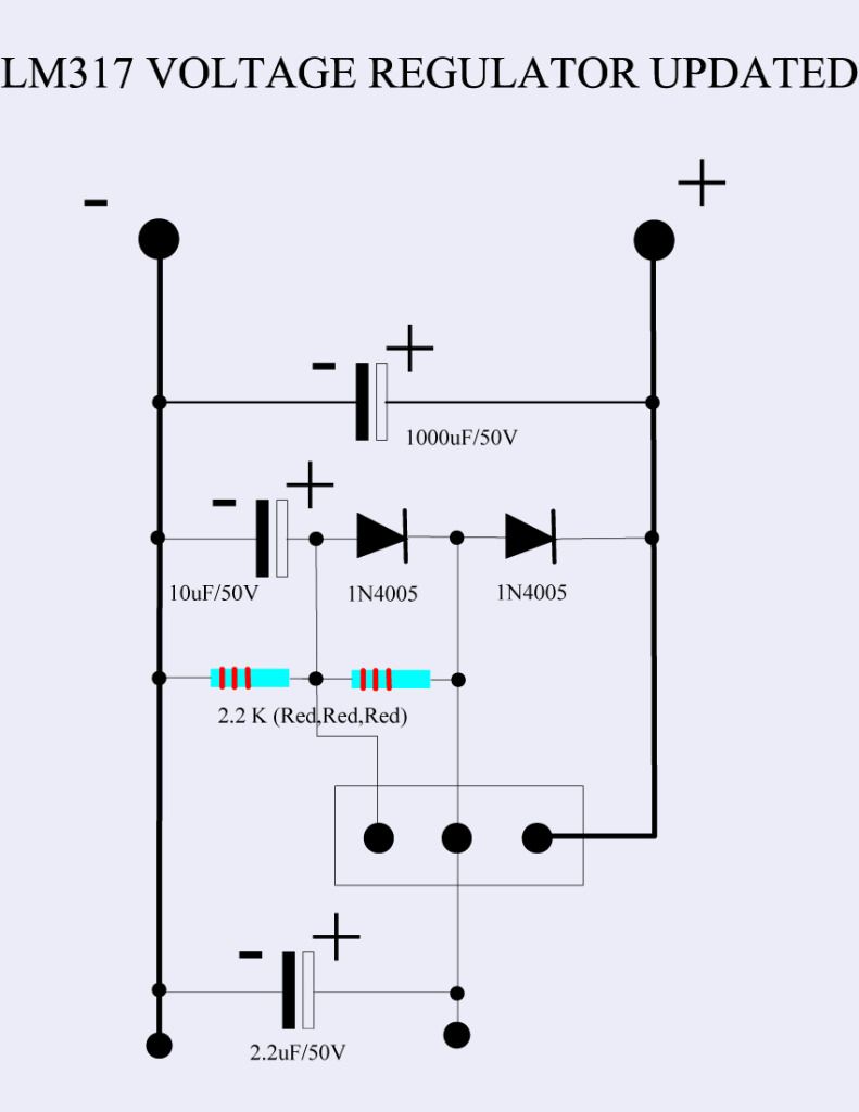

    It has an imput of 38v and output 12.4v

    Kind regards

    Comment


    • Originally posted by torpex View Post
      Hi all,

      There are other questions in this schematic:


      It is correct the value of R4 resistor to 10k? This sets the output, right?

      It is correct the value of R1 resistor to 1k and R2 to 18K? If this is so the input current is too limited.

      How do you set the frequency? Because VR is to adjust the pulse width, right?
      This setup run with frequency fixed around 529 Hz and only adjust pwm (i think).


      Unless I am missing something, you are right about the current to the voltage regulator... it's limited to less than 2 milliamp (0.002 Amps). This could cause some problems.

      I am not sure torpex, but I think this is an adjustable frequency circuit with 50% duty cycle. Too tired to figure it out.

      Regards
      Larry

      Comment


      • Awesome Bob!!

        Originally posted by bobfrench@fastmail.fm View Post
        UFO,

        I can't spend the time right now to tell you all the stuff that I have done lately, but I will get back to you in detail in hopefully in a day or two.

        I posted pics in Photobucket, one of which is a commercially made (in Russia) spark gap bulb a little bigger than a NE-2 glowing purple.

        I found that if I feed BOTH ends of the CF coil to one leg of an NE-2 and ground the other leg to me or a free-standing coil it glows. Then if I moved the ground to the Neg Output of the UFO device BOTH the NE-2 and the neon that I have on the Output get brighter.

        Then if I ground the Neg. Input to a free-standing coil the output of the CF coil increases from, say, 86v to 130v...about 50%.

        Gotta go,

        Bob

        Hello Bob!!

        You are right on my friend!!
        You have entered in a very nice stage of Radiant...How incredibly She could spread within your "space"...then is all over.
        I have done similar testing but I do not have a "Russian Spark Gap Bulb"..(btw, it sounds like a great device!!) I have tried with Plasma lamps and regular spark gaps I have made (like I told you, based on old carbon brushes)...then She gets every where...it is an amazing and beautiful experience and I am really enjoying the fact you have experienced it!!

        It will also enhance brightness around the center of Coil, and if you have a core (paracore?) I had steel one, then it will enhance it even more near its area as you get closer...And the same thing happened that took me by surprise...is that also lite up at oscillator area...
        If you get it to ground...it will enhance it, like you've said...and all coils around get "excited"...
        I can see you are having it even greater magnification with that CF Secondary Coil...WOW, nice!!

        Very glad you've made this test!!

        Please, whenever have a chance please write some more of this...I love it!!


        Thanks Bob!!


        Regards


        Ufopolitics


        P.D: Larry Ross...this is Radiant my friend...no other electricity could do this effects.
        Principles for the Development of a Complete Mind: Study the science of art. Study the art of science. Develop your senses- especially learn how to see. Realize that everything connects to everything else.― Leonardo da Vinci

        Comment


        • Originally posted by larryross View Post
          Unless I am missing something, you are right about the current to the voltage regulator... it's limited to less than 2 milliamp (0.002 Amps). This could cause some problems.

          I am not sure torpex, but I think this is an adjustable frequency circuit with 50% duty cycle. Too tired to figure it out.

          Regards
          Larry
          Hello Larry,

          Sorry was busy...You've got it right, is fixed to 50% duty cycle...PWM, Frequency is adjustable...that's all...

          Regards

          Ufopolitics
          Last edited by Ufopolitics; 06-27-2012, 05:50 AM.
          Principles for the Development of a Complete Mind: Study the science of art. Study the art of science. Develop your senses- especially learn how to see. Realize that everything connects to everything else.― Leonardo da Vinci

          Comment


          • Kogs new setup

            Originally posted by torpex View Post
            Hi Kogs,
            It's the best, with a single MOSFET.
            Recalls that already discussed, you can even use other cheaper model to try.

            We must learn to start the circuit, because according to the settings ... can be forced and burn. Even if everything is correct.

            I use the dmm in 10 AMPS DC mode to control the drain current. No switch to test, only probe to negative.
            An example of my setup with 9w bulb for test:
            Start and pots to 0: 0.02-0.03 A
            Pot PW (this is a dangerous) up slowly to 0.5 A, the bulb flashes or lit.
            Pot FR (frequency) this affects less than PW.
            If there are readings of more than 2-3 amps is a sign that something is wrong, disconnect and check.

            Good luck


            G'Day Torpex
            I appreciate your input I am really

            I am using the 555timer Oscilator it only alters the duty cycle
            I see you are using one like Bob's Modified one

            Perhaps I should change to that one

            I have 4 IRFZ46NPBF mosfets I will use one of them

            I have plenty of heavy wire 1.25 mm and 1.5 mm I was going to replicate JB's Ferris wheel but he said unless you build it to the size he did I would be dissapointed So I discontinued with it. I already had bought the wire
            The coil I have is a large one 583 feet 5/.8mm litzed soldered each end to make parallel wires measuring 1.3 ohms.
            I do not have any other wire than some .8mm 100feet lengths

            I was perhaps wondering if I have the Diodes at the output the wrong way around (I don't think so ) perhaps I am wrong in my

            Regards

            Comment


            • Originally posted by iankoglin View Post
              G'Day Torpex
              There was some time back a dissucion with regard the above mentioned Voltage regulator Page 9 post 256 R2,R1 done away with and R3 changed to 2k2 and another 2k2 added R4 cganged to a 10uf 50v cap and another 2.2uf 50v cap added
              the outcome was Here and this is the one I used


              It has an imput of 38v and output 12.4v

              Kind regards

              Hello Ian, Torpex...

              If you look further on this posts of the regulator, I have made a CORRECTION...the center resistor between legs of LM317 is 220 Ohms, and NOT 2200 ohms!!...
              The one to ground IS 2.2K or 2200 Ohms
              Sorry about that!


              Regards

              Ufopolitics
              Principles for the Development of a Complete Mind: Study the science of art. Study the art of science. Develop your senses- especially learn how to see. Realize that everything connects to everything else.― Leonardo da Vinci

              Comment


              • Insulating CF

                Hi UFOpolitics

                Very interesting thread, especially on the use of carbon fibre. Coming from an aviation background these static dischargers are now making more sense. I wondered for insulating the carbon fibre if drawing it through aquarium piping, which is quite thin, (some made of silicon and others PTFE -Teflon )would be a quick and satisfactory way of doing it? I guess attach the CF to a bit of iron wire and the CF could be coaxed through with a magnet – anyway just a thought.

                Regards

                John

                Comment


                • Originally posted by iankoglin View Post
                  I have 4 IRFZ46NPBF mosfets I will use one of them
                  Hi @Kogs,
                  These models are not suitable, support only 50V


                  Regards
                  http://Cacharreo.com.es/foro

                  Comment


                  • Cf

                    Hi All
                    The carbon tape shaped stuff has its own covering and can be just rolled onto the coil. The 1K tow is vacumed thru 100 foot 1/16 heat shrink. Bob does the magnet trick but it takes hours for a 12 foot piece. It seems that the more CF you use(more space for her) the better.
                    Dana
                    "Today's scientist have substituted mathematics for experiments and they wander off through equation after equation and eventually build a structure which has no relation to reality."
                    Nikola Tesla

                    Comment


                    • Originally posted by Ufopolitics View Post
                      Hello Larry,

                      Sorry was busy...You've got it right, is fixed to 50% duty cycle...PWM, Frequency is adjustable...that's all...

                      Regards

                      Ufopolitics
                      Hi UFO,

                      I haven't commented much. But I have read through this thread (multiple times), have the circuit built, and have been playing around with it.

                      With regards to this circuit and the 555, I suspected the duty cycle was pegged at 50%. Glad you confirmed it. Because of that, I have moved on from the 555. I'm basically just using the MOSFET part of the circuit now, triggered by a function generator. This allows precise control of the frequency and duty cycle.

                      I have found that using such a high duty cycle (50%), especially at the lower frequencies, is really too much for the MOSFETs to handle. Especially if the coil isn't large enough or has really low resistance, as others have mentioned. I think this is where a lot of people are having issues. On the lower frequencies you are really pulling a lot of current at 50% duty cycle. This can easily be verified if you have an analog ammeter hooked up.

                      Having said that, I have found that there is a correlation between frequency/duty cycle/radiant energy. The lower the frequency, the lower the duty cycle needs to be to draw the radiant in. As you dial up the frequency, you have to dial up the duty cycle to keep in the radiant. It's very easy to see on a scope and on the CFL as well. With the 555 setup and the duty cycle pegged at 50%, everyone will dial in optimal radiant at different frequencies, and this is purely based on the difference in coils that everyone is using. I think it will be very difficult for people to draw in radiant at low frequencies with this setup. Especially with the risk of blowing the MOSFETs. I believe everyone needs to evolve their circuit to have adjustable duty cycle.

                      With regards to coils, I have found that larger coils also allows you to draw radiant in at lower frequencies and lower duty cycles. I have also tried using different core materials, from welding rods to Paracore to air coil. I seem to get the best results, highest radiant spikes with air coil.

                      Anyway, just a few things I have discovered so far. UFO, since I am up and running and have a pretty diverse setup, I can do whatever testing you might like. Are you still interested in frequencies before/after diodes, etc.? Let me know, I'm happy to contribute.

                      Few other things, as Bob has mentioned, this thing is GREAT as charging batteries. I have also lit neons just attaching the positive wire from the radiant side. You can ground the other end almost anywhere and it will glow. I was standing barefoot on carpet, holding one end of the neon with the other connected to the positive of the radiant side and the thing would light up!

                      Great stuff!

                      Regards,

                      Jason
                      Last edited by greekstile; 06-27-2012, 12:04 PM.

                      Comment


                      • Originally posted by prochiro View Post
                        Hi All
                        The carbon tape shaped stuff has its own covering and can be just rolled onto the coil. The 1K tow is vacumed thru 100 foot 1/16 heat shrink. Bob does the magnet trick but it takes hours for a 12 foot piece. It seems that the more CF you use(more space for her) the better.
                        Dana
                        Hi prochiro

                        What would your thoughts about using plastic dip? I have a reel of 12K tow on order. Are you saying its better to have spacing between the CF turns, or should you tightly wrap it, getting the most amount of CF into a space?

                        http://www.plastidip.co.uk/eStore/in...w&pid=PDL-0008


                        Regards

                        John

                        Comment


                        • Hi all,

                          I've been checking the original ufo circuit in protoboard, without LM317, directly to 12v:


                          Works ok
                          Lit the 9w bulb with 12v only.
                          Maybe a little less effective than the others.

                          Unfortunately I have problems with my frequency counter. These are the readings that I have obtained with mosfets disconnected:
                          Pot 0: 501 Hz
                          Pot 1/2: 454 Hz
                          Pot full: 497 Hz
                          Also in 0 to 1/2 range: 0, jump to 110, climb to 454 in abrupt steps (little trimpot).
                          I tried with a 12v bulb and an npn transistor in 'visual mode', lit gradually from 0 to 100%.
                          I think it is a displacement of frequency of the 555 in pwm mode.

                          Using other oscillators I hear the coil when changing the frequency.


                          @Ufo
                          My problem is that efficiency is approximately 80-85%, when I put more load also I have to raise the drain current proportionately.
                          I've only tested up to 70W load

                          Still do not know if this is the radiant, but if so, the question is:
                          What I can do with it?


                          Regards
                          http://Cacharreo.com.es/foro

                          Comment


                          • Hello Greekstyle!!

                            Originally posted by greekstile View Post
                            Hi UFO,

                            I haven't commented much. But I have read through this thread (multiple times), have the circuit built, and have been playing around with it.

                            With regards to this circuit and the 555, I suspected the duty cycle was pegged at 50%. Glad you confirmed it. Because of that, I have moved on from the 555. I'm basically just using the MOSFET part of the circuit now, triggered by a function generator. This allows precise control of the frequency and duty cycle.

                            I have found that using such a high duty cycle (50%), especially at the lower frequencies, is really too much for the MOSFETs to handle. Especially if the coil isn't large enough or has really low resistance, as others have mentioned. I think this is where a lot of people are having issues. On the lower frequencies you are really pulling a lot of current at 50% duty cycle. This can easily be verified if you have an analog ammeter hooked up.

                            Having said that, I have found that there is a correlation between frequency/duty cycle/radiant energy. The lower the frequency, the lower the duty cycle needs to be to draw the radiant in. As you dial up the frequency, you have to dial up the duty cycle to keep in the radiant. It's very easy to see on a scope and on the CFL as well. With the 555 setup and the duty cycle pegged at 50%, everyone will dial in optimal radiant at different frequencies, and this is purely based on the difference in coils that everyone is using. I think it will be very difficult for people to draw in radiant at low frequencies with this setup. Especially with the risk of blowing the MOSFETs. I believe everyone needs to evolve their circuit to have adjustable duty cycle.

                            With regards to coils, I have found that larger coils also allows you to draw radiant in at lower frequencies and lower duty cycles. I have also tried using different core materials, from welding rods to Paracore to air coil. I seem to get the best results, highest radiant spikes with air coil.

                            Anyway, just a few things I have discovered so far. UFO, since I am up and running and have a pretty diverse setup, I can do whatever testing you might like. Are you still interested in frequencies before/after diodes, etc.? Let me know, I'm happy to contribute.

                            Few other things, as Bob has mentioned, this thing is GREAT as charging batteries. I have also lit neons just attaching the positive wire from the radiant side. You can ground the other end almost anywhere and it will glow. I was standing barefoot on carpet, holding one end of the neon with the other connected to the positive of the radiant side and the thing would light up!

                            Great stuff!

                            Regards,

                            Jason

                            Hello Jason,

                            Great input!!

                            Thanks for your great advice and sharing here the differences and the stress for Mosfets at Low Freq/Higher Duty Cycle...You are completely right, and honestly, I never thought of it.
                            We have further on the LM339 or LM393 Circuit that Mad Scientist provided a bit back on this thread, and also the latest and great one that member John Stone kindly and patiently put together for all of Us here in excellent detail...

                            My circuit with the 555 was just my primary and simple one for those members coming in new to make their tests...Although I am still using it, have not got the time to make the ones with adjusted duty cycle, however, I do know, because I have posted here...that lowering the Cycle at low and also at higher Frequencies gets Radiant at a very small percentage of energy spent on our side...making the COP much more efficient...

                            You have asked for a test you could do for Us...and I will ask you to please run a test at the lowest duty cycle possible with the Highest Frequencies possible where We get Radiant in galore...and post all results with the required parameters behavior-readings on main values to be able to evaluate COP of this set up...I will love to hear-read this, if you could. Thanks in advance!

                            I have been devoted to prepare my documents, videos and models in reality and in 3D and CAT, for all of you on the "Real Game" to come soon...The Motors and Generators design. Where all this Coils and Oscillators will come up to play the role in direct applications to all of them. ...This is not the end of my disclosure, but just the very beginning, and I really appreciate all of those- like you- that have come here with a very positive attitude and willing to contribute and help Us develop this faster.

                            So, bare with me here...I will be showing all this very soon.


                            Regards


                            Ufopolitics
                            Principles for the Development of a Complete Mind: Study the science of art. Study the art of science. Develop your senses- especially learn how to see. Realize that everything connects to everything else.― Leonardo da Vinci

                            Comment


                            • Originally posted by iankoglin View Post
                              PS

                              Perhaps I could try it with only 1 or 2 Mosfets as it is very expensive destroying 6 at a time

                              Kogs
                              Ian
                              The problem with using fewer fets is that each fet carries part of the load... as you take more fets out, the higher risk is to blow remaining fets as they are now taking more of the load. With only 1 fet I think you will blow more easily, because 1 is taking all the load.
                              If you use the resistor I recommended and set it up as I said the max current draw you can get from the load is .222Amps (220mA) which can't hurt the fets.
                              Before you can fix your problem, work hard to isolate the problem to find out where the it is. If you make guesses then try something you might blow a lot of parts before you find the problem (accidentally stumble across it).
                              This is the last time I will interject... if you chose to do it on your own or other way, I wish you luck my friend.

                              Regards
                              Larry

                              Comment


                              • Originally posted by torpex View Post
                                Hi all,

                                I've been checking the original ufo circuit in protoboard, without LM317, directly to 12v:


                                Works ok
                                Lit the 9w bulb with 12v only.
                                Maybe a little less effective than the others.

                                Unfortunately I have problems with my frequency counter. These are the readings that I have obtained with mosfets disconnected:
                                Pot 0: 501 Hz
                                Pot 1/2: 454 Hz
                                Pot full: 497 Hz
                                Also in 0 to 1/2 range: 0, jump to 110, climb to 454 in abrupt steps (little trimpot).
                                I tried with a 12v bulb and an npn transistor in 'visual mode', lit gradually from 0 to 100%.
                                I think it is a displacement of frequency of the 555 in pwm mode.

                                Using other oscillators I hear the coil when changing the frequency.


                                @Ufo
                                My problem is that efficiency is approximately 80-85%, when I put more load also I have to raise the drain current proportionately.
                                I've only tested up to 70W load

                                Still do not know if this is the radiant, but if so, the question is:
                                What I can do with it?


                                Hi torpex
                                Unless I missed something it appears to be your trim pot is faulty. Is that an audio trim pot or a linear pot or any number of other types of pots? If UFO's explanation is correct and I have no reason to think it isn't, you have to dial in radiant slowly not in large jumps. You must get your low end frequency down to under 100Hz and smooth out your frequency increase before you can achieve radiant. My guess is, If your efficiency isn't > 100%, you don't have radiant. Also if your duty cycle is set at 50% it will be harder. I don't pretend to know anything about radiant, just presenting what I understand from UFO's statements.

                                P.S. the worse way to build an oscillator circuit is on a proto board. When I designed for a living I gave up on proto boards early, because they were just too much trouble. A circuit that worked on a proto board didn't always work when transferred to a circuit board.


                                Hope this helps
                                Larry
                                Last edited by larryross; 06-27-2012, 04:34 PM.

                                Comment

                                Working...
                                X