Announcement

Collapse
No announcement yet.

My Motors got me to Tap into Radiant Energy

Collapse
X
 
  • Filter
  • Time
  • Show
Clear All
new posts

  • Hello kEhYo77

    Originally posted by kEhYo77 View Post
    Hi again @All
    Finaly I've got my setup with a CLF going after accidental signal generator damage...
    Inductive Collapse Lighting a CFL
    In this short clip I am lighting a CFL by pulsing a pancake coil and catching the BEMF from inductive collapse of the coil's magnetic field.
    There is a secondary winding tuned with a capacitor to form a LC tank circuit to resonate at lower harmonic frequency of the primary (250kHz&50kHz).
    On a scope across the tank circuit I see a pretty clean sine wave.
    Two batteries supply 24V to the pancake coil through a MOSFET.

    I am eagerly waiting for the animations Ufo.
    I am into 3D CGI too need some help with rendering? I use NewTek's LightWave 3D

    kEhYo


    Hello kEhYo77,

    Nice set there!!

    I use the old MAYA 3D and I love it!!...but batch rendering I have to perform in After Effects, and premiere also...well for final tracks blending-editing.

    I have built my own machines (Servers) with very nice VPU's Video Cards and pretty big capacity HD...One Terabyte...RAM is also fine...but you know videos take tons of space...but is ok...will see it soon.


    Thanks and regards


    Ufopolitics
    Principles for the Development of a Complete Mind: Study the science of art. Study the art of science. Develop your senses- especially learn how to see. Realize that everything connects to everything else.― Leonardo da Vinci

    Comment


    • Bipolar

      I was wondering why the bedini/cole circuit is not used for the driver section?
      Here is the schematic I am using a hall on the front end and you can replace the 470 ohm resistors with 1k pots to offset the switching from each MJL

      Here you can see that if you use the h11d1 with (I actually ended up using a 2955) this you can then use far less current to fully switch. I was using as much as a 20k and still getting good switching. But the important thing is that you can use the op-amp circuit and only need the one stage.

      Anyway hope this is helpful. I think it would simplify things and have a lot less chance of the loss of costly Fet's...

      Les

      Comment


      • opto's

        Hi folks,

        Just finished hooking up my opto/driver, as a low side switch with small incandesent, worked great switching 24v.

        Then tried a hi/lo switch with the small light, and it worked great.

        I will hook up my coil tomorrow, I am sure it will work great.
        Thanks John Stone.

        One thing, be sure to check +/- input to your dc/dc converter,
        pin 1 was -vin and i hooked up +12v, good thing I bought 4.

        Thug

        Comment


        • Kogs Oscillator output

          Originally posted by larryross View Post
          Don't check your oscillator output with a DMM... only use a scope. The DMM gives you the average (RMS) output and not the amplitude of the signal feeding the FETs base. Changing the duty cycle of the oscillator will change the RMS output of the oscillator, but should not change the amplitude of the signal. You need at least 4V signal amplitude to turn on the FET and your oscillator should be putting out between 10V and 12V amplitude at any frequency or duty cycle. How are you coming up with 0.4% duty cycle? 5% is really hard to see on a scope?


          Exactly what are you saying here? You are getting regulator output (13.4V), but you aren't getting any oscillator output after you attach the FETS? Do you have a coil attached to the FETs?


          If your oscillator works before you attached the FETs and not after you attach the FETs, it most likely isn't your oscillator, but your FET circuit. You could switch oscillators all day and not fix anything. After you attach the FETs, what dose your oscillator output look like on a scope?
          If not oscillating, is it high or low? This will give you a clue as to what the FETs are doing to your oscillator.

          Let me know the answers to all questions I asked here... I can't help if I don't know.

          Regards
          Larry
          G'Day Larry
          My Regulator input 38.? volts output 13.5v Its OK
          The Oscillator has only one pot I was measuring with a DMM. There was from 0.4% to 99% Duty Cycle the Hertz was varying as the Pot changed from 0 to full on 50K I did not use My Scope as I have not as yet really understood how to connect it to read the Hertz or Duty cycle with it so I have to study it a bit more.

          The CFL Bulb did not light so I checked the voltage on the output after the diodes and there was something like 4.?V The voltage before the diodes should have been the same as the Battery voltage it was not, I should keep the readings but I didn't, even the Drain was reading very little I just can't remember what it was but it should have been at least the same as the battery I

          I made a single Mosfet circuit the same as the 6 Mosfet circuit connected to a 36v bulb (3 x 12v in series)load with 36v into the regulator the output switching on the single mosfet circuit and the light came on fully bright.

          On the main circuit I disconnected the coil and diodes, I then connected the 36v bulb as a load in place of the CFL bulb. When I ran the setup including the Oscillator the Bulbs did not light up. When I disconnected the Oscillator and ran the output of the Regulator to the input of the Mosfet circuit the 36v bulbs lit up quite bright so it is quite obvious that it's only the Oscillator that is not working

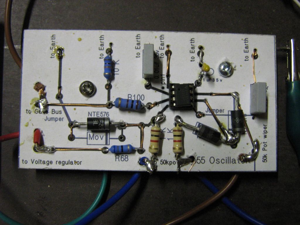
          When I made up this Oscillator circuit I used the Large Diodes which I now realise was an over kill but I was told that it should still work OK here is the circuit


          Perhaps I should replace the large diodes.
          Please Larry what do you think?

          Kindest regards

          Still Hard at it

          Comment


          • Hi to all my US friends.. Nice to Know UFO is OK -

            where I put together a five pole little brush motor (Radio Shack part#273-256)
            Any suggestions as to where I can buy a couple of these motors.. Seems that there is no shipping to international customers and I am "down under"

            I would appreciate any suggestions.
            Cheers
            AmpsVolts

            Comment


            • Hello Ampsvolts

              Originally posted by ampsvolts View Post
              Hi to all my US friends.. Nice to Know UFO is OK -


              Any suggestions as to where I can buy a couple of these motors.. Seems that there is no shipping to international customers and I am "down under"

              I would appreciate any suggestions.
              Cheers
              AmpsVolts
              Hello Ampsvolts,

              Sorry about that...but do not worry, it is just a "Toy Motor", however, it is based on a Five Pole Armature or rotor, and 2 permanent magnets stators...The reason I chose that one is because it is pretty cheap...and easy to convert into an Asymmetrical Model.

              Now, it will also work a Three Pole armature with two stators...for now, I would like to Keep It Simple...and not going into more clever design machines.
              So please do not spend too much money, into a "sophisticated one"...

              I will start with low armature poles videos and explanations...3 and 5...but after you learn the procedure, I know you will make almost anyone into this Tech...
              The most important part is that they both be, the same exact motors, same rotor number of poles, same shaft diameter,same stator number...meaning, same model.


              Regards


              Ufopolitics
              Last edited by Ufopolitics; 07-07-2012, 08:53 AM.
              Principles for the Development of a Complete Mind: Study the science of art. Study the art of science. Develop your senses- especially learn how to see. Realize that everything connects to everything else.― Leonardo da Vinci

              Comment


              • Radioshack UK

                Hi All

                Glad you came back UFOpolitics - worried like the rest!

                Here's a link to the High-Speed 9-18VDC Motor in the UK:

                RadioShack® Super Speed 9-18VDC Hobby Motor - RadioShack.com


                Regards

                John

                Comment


                • Hello Kogs,

                  Too bad your still having trouble.

                  1. Just replace the 555 and see.

                  2. Ian, if I were you, I would buy a breadboard, to build a prototype, at least until you get become really good at building circuits, I know some people will disagree, but its a pain soldering and removing components, until you have a working circuit. just my opinion.

                  3. I would start with the simplist, 555 from Rymcybernetics, its posted back somewherere, but seperate your signal from your switching voltage. The way they draw it, you will need protection or you will fry 555's and 393's.

                  or

                  Do mad scientist circuit, less complicated then John's but works good to get started. You really cannot isolate duty from frequency adjust with the 555, no matter how you connect.

                  4. Maybe you did this, but post a schematic of your circuit, not the one you want to build, but the exact one you have built.

                  Also, hook up a cap, that will flash the test light in visable range, then you can see if the oscillator is working.

                  We'll get her going Ian

                  Thug

                  Comment


                  • [
                    Originally posted by iankoglin View Post
                    G'Day Larry
                    My Regulator input 38.? volts output 13.5v Its OK
                    The Oscillator has only one pot I was measuring with a DMM. There was from 0.4% to 99% Duty Cycle the Hertz was varying as the Pot changed from 0 to full on 50K I did not use My Scope as I have not as yet really understood how to connect it to read the Hertz or Duty cycle with it so I have to study it a bit more.
                    Stop ever thing and learn to use your scope. You will save time in the long run.

                    The CFL Bulb did not light so I checked the voltage on the output after the diodes and there was something like 4.?V The voltage before the diodes should have been the same as the Battery voltage it was not, I should keep the readings but I didn't, even the Drain was reading very little I just can't remember what it was but it should have been at least the same as the battery I

                    I made a single Mosfet circuit the same as the 6 Mosfet circuit connected to a 36v bulb (3 x 12v in series)load with 36v into the regulator the output switching on the single mosfet circuit and the light came on fully bright.

                    On the main circuit I disconnected the coil and diodes, I then connected the 36v bulb as a load in place of the CFL bulb. When I ran the setup including the Oscillator the Bulbs did not light up. When I disconnected the Oscillator and ran the output of the Regulator to the input of the Mosfet circuit the 36v bulbs lit up quite bright so it is quite obvious that it's only the Oscillator that is not working
                    The only thing that is obvious is that your FET board has a major problem. Without anything to trigger the mosfets (turn them on) you shouldn't have gotten the light to light the way you did it. If your oscillator works with out the fet board connected and not after words how could it be anything else other than the FET board?

                    When I made up this Oscillator circuit I used the Large Diodes which I now realise was an over kill but I was told that it should still work OK here is the circuit


                    Perhaps I should replace the large diodes.
                    Please Larry what do you think?

                    Kindest regards

                    Still Hard at it
                    Honestly I have been at this for a long time and I wouldn't think of working on this project without a scope. You are basically blind in one eye and can't see out of the other. There is no way to track down where the signal stops or at what state it stopped or if it even actually did stop if you can't see it and a DMM will tell you nothing helpful unless you know enough to be able to translate what you are seeing and at that it is very limited. Use your DMM to check your battery state and circuit resistance... that's all it is good for in the world of electronics.
                    Considering the handy cap we are working under I am convinced it is your FET board unless you have the coil hooked up also then it could have something to do with it... you have no way of knowing which is bad with both hooked up. The art of diagnoses is to separate, test each circuit for proper operation then eliminate the problem. If you have 2 circuit hooked up and they aren't working then it could be either one. Either separate them and test individually or replace both.

                    Sorry I can't be of better help.
                    Regards
                    Larry

                    Comment


                    • Ian
                      I see 2 pots on your circuit board. I assume the 50K pot is for the frequency adjust, but what is the other one for?

                      Regards
                      Larry

                      Comment


                      • Motors, schem...

                        Ok, Got two motors.. They actually had the right ones. Wow!
                        Looks like I would need a micro-scope if we are going to do something inside there...

                        And I Tried to post the schematic, didn't realize it didn't take. I guess I am all out of space here... apologies....

                        Les

                        Comment


                        • UFO,
                          I want to start by saying thanks for starting this thread and sharing your knowledge. Great work going on here!
                          I'm lookin to build the lm339 circuit posted earlier in the thread but have a question about a component. I've attatched the drawing and dont know what this circled item is??
                          Can someone identify this component?


                          EDIT: my pic wont attatch for some reason! There is some component above the lm339 with a cap across the leads, I cant tell what this is. I'll try to get this pic posted.
                          Link for pic: Circuit -rev. 2 picture by bobfrench - Photobucket

                          Edit #2- I think I got it, is this just a terminal to feed the voltage regulator?
                          Last edited by pmazz850; 07-07-2012, 11:57 PM. Reason: add link

                          Comment


                          • Originally posted by thugugly View Post
                            ...Just finished hooking up my opto/driver, as a low side switch ......Then tried a hi/lo switch with the small light, and it worked great.
                            Hi Thug,
                            do you say that you have built your isolated driver circuit conforming my suggested circuit? I still had no time left to finish building. If you confirm the replication we can release it and encourage others to build it as well.
                            Did you make any modifications?
                            rgds John
                            Experts spend hours a day in order to question their doing while others stopped thinking feeling they were professionals.

                            Comment


                            • JohnStone,

                              All I had time to do so far is ;

                              1. Built low side switch, tested with small incandescent, it lit and flashed.

                              2. Connected coil with low side switch, worked, and lit cfl, around 300 Hz.

                              3. Connected incandescent light to Lo and hi side, lit and flashed well. I have a vid ( sorry it's not great quality), which I will load for you as soon as I get home tonight.

                              I was only switching 24 v.

                              4. Hooked up coil, and puff, I lost my dc/dc converter, on the high side, at least it got very hot, I shut it down and had to leave, so I'm not sure what has happened yet.

                              John, I know I suck at vids, so please, tell me what you need me to do if its no good, where you would like scope shots, etc.

                              Thug

                              Comment


                              • @thug & All

                                I tried the high-low side driven switch like that and had similar problems. Smoked some silicone too
                                In the driver's datasheet there info on suppressing negative transients when hard switching inductive loads by adding more resistance to the gate lead. Eventually I abandoned that config and I am working with low side only MOSFETs and IGBTs with low RdsON and high dv/dt
                                Tesla did abrupt switching with spark gap and mercury type low resistance commutators and others confirm that the BEMF effect is most powerful when the time to turn on/off the transistor approaches 0!

                                kEhYo
                                “ THE PERSON WHO SAYS IT CANNOT BE DONE SHOULD NOT INTERRUPT THE PERSON DOING IT ! ”

                                Comment

                                Working...
                                X