Announcement

Collapse
No announcement yet.

My Motors got me to Tap into Radiant Energy

Collapse
X
 
  • Filter
  • Time
  • Show
Clear All
new posts

  • #31
    @Ufopolitics Thank you for explanation. I ran couple tests and observed circuit behavior in resonant state. I tried incandescent bulb, as well as bulb in series with battery (just to try out some ideas).
    My output freq. during first test was 13.5-15kHz, which I found to be the best resonant spot at lowest input A and best charging rate. I mainly rely on my scope reading. Transistor remains cold. I'll try to find my ultra fast diodes hiding from me but not sure if they're rated that high.
    I'm curious about the different oscillator you have mentioned.


    Vtech
    'Get it all on record now - get the films - get the witnesses -because somewhere down the road of history some bastard will get up and say that this never happened'

    General D.Eisenhower


    http://www.nvtronics.org

    Comment


    • #32
      Originally posted by Ufopolitics View Post


      Ok, here I drew a better circuit, arranged the components in a more understandable fashion. (And put letters to all ) However, I am also adding the magnetic polarity of Coil at both stages of Oscillator signals, Red is our "Artificially" created Magnetic Field result of our Input to Coil. Blue is the Naturally created by Radiant Energy opposite magnetic field...
      Now, what we are getting out are "Pure Inductance Counter Electro Motive Forces (As Physics Says)...or Back EMF.
      The Field created by Radiant Energy is way bigger in spectrum, flux force and of a MUCH Higher Frequency than Our Input created Field. In my previous picture of the Fluorescent Lamp 125 Watts, the two Extech meters are showing Hertz on both fields, left at 2033Hz is Radiant, right meter 800Hz is ours. In the video, I uploaded in YT, by final part, when I am turning on-off by hand, you could see meters deflect at Load-No Load. However, always keeping the differences between them. If there is a certain time with no load, the Radiant Field becomes 'Stabilized' with Primary (Ours), meaning same Hz...
      Now , just to go over some Physics Concepts related to Inductors versus Motor Generator Coils.

      Physics says that the reason the Inductor changes polarities is due to the Collapsing of the ORIGINATING Field, where "The shrinking" of the Magnetic Field, starts changing direction of the flux lines cutting the wires lines in an opposite direction, therefore,inductor shows reversed polarities. They also say is due to Inductor trying to keep current (I) Constant.
      When Physics explains the same exact phenomena, (A Simple Coil of Enameled Wire) but applying it to Dynamo-electric Machines...then 'remembers' about Faraday's Laws...mentioning is a "Dragging Force" THEN, call it C EMF, not related to Electro Magnetic Fields, BUT instead, to Electro 'Motive Force'...and it is a very high coincidence, the fact that even the meaning been so different, the "Letters are Identical"...How could we dispute which is which between C EMF or C EMF?

      The readings of the Radiant Energy Electromagnetic Field, at all shows, the least signs to be collapsing, fading or shrinking, on the contrary, it is Superior in many parameters to the "Originating" One. And been Opposite in Polarity Orientation, is understood that its Output Voltage is reverse of ours.
      However, since Inductors are static components, and do not play any roll into 'Magnetic Interactions' , we could say that mentioning about Magnetic fields reversing, is "not that important"...

      I have tried this output on typical DC brush motors, they go beyond estimated top speed...rated to go that fast at a consumption of @ 36 Volts, However using this just simple arrangement of Coil-Diodes it uses 4.0 Volts, going over speed limits, but the must impressive thing is...as they accelerate they become much colder...I will be filming this and using an Infrared Digital Thermometer...

      The Diodes should be the lowest resistance than the IN4000 family (rated @600 Ohms)...I use the NTE576...rated at 400 Volts and @400Ohms. besides being a bigger body diode...however, I have Blown them with low voltage input but RE feed back spikes when Load was 'demanding too much' ...but there are many available that would do the job, Fast Switching is very Important!

      Well, I think this is all I wanted to say...besides thanking all of you for being so patient and nice to me.

      So See You tomorrow...
      And have a nice evening!

      Ufopolitics
      Looks like your harvesting the collapsing magnetic field to me.

      How do you say your not just using the emf from the collapsing magnetic field ?

      Here's my opinion.

      Your output arrow is going the wrong way, input goes into the positive of the
      coil, which you've drawn correctly, but the output goes out of the opposite
      end of the same coil as emf, which is just added to the original emf "if the coil
      is in series with a load and the source", the collapsing magnetic field is delayed emf in the
      same direction as the applied emf (your diodes indicate this fact), and the
      magnetic field doesn't get there for free.

      Just because in most circuits where there is a coil in parallel with the source
      (like a motor) the magnetic field collapse is usually wasted, doesn't mean
      when you collect it it is free energy.

      In my opinion going by what I have picked up, bemf is a force which opposes
      current caused by emf, bemf does not ever cause it's own current because it
      is always slightly less in force than the applied emf, if it wasn't less no current
      would flow and it only ever appears to oppose current caused by applied emf.

      When a coil is charging there is bemf opposing the charging current and when
      the coil is discharged there is bemf opposing the emf produced by the
      collapsing magnetic field, the emf produced by the collapsing magnetic field is
      normal forward emf, but it's origin is the coil not the source, the potential the
      coil has before collapse (the magnetic field) is caused by the current through
      it from the source.

      Cheers

      Comment


      • #33
        Here's how I would draw it.

        The top drawing the load in series with the coil and the source by adding a
        capacitor in series with the coil the emf from the collapsing magnetic field is
        automatically collected, if a diode is placed between the battery + and the coil
        the capacitor cannot discharge back to the battery after it is charged by the
        coil and so the capacitor if sized correctly will be charged to double the
        battery voltage by the emf from the coils field collapse. If the frequency is
        correct the diode is not needed, On switch off the magnetic field collapse
        charges the capacitor to double the source voltage then on switch on the
        capacitor discharges through the load. Works a treat.

        The bottom drawing is the coil in parallel with the load and the emf from the
        coil just discharges through the load, and because the collapse is not limited
        by a voltage it can be discharged back to the battery positive, but it would
        discharge to the negative if configured to allowed it to do so.


        Uploaded with ImageShack.us

        The way I see it when there is current flowing there is bemf but the bemf is caused only to oppose the current caused by the emf.

        Bottom line is the emf produced by the collapsing magnetic field of the coil is forward emf not bemf.

        Cheers
        Last edited by Farmhand; 02-08-2012, 07:08 AM.

        Comment


        • #34
          Gotta Love it.

          So about 8 years ago I built this very same motor on my own. I used a set of points, transistors, Fets, relays, all kinds of switch's. Simple Motor
          It just interests me how it someone else rediscovered.

          So instead of complaining or anything let me give some assets, so you read further into what you are doing. It is a very conventionally used circiut.

          Boost converter - Wikipedia, the free encyclopedia

          John Bedini's patent

          And there is one other link for a patent from Toyota back in the 70's, but it evaids at the moment.

          The joule thief's all work this way.

          You just stepping up voltage. You may be harvesting the collapsing field to some extent but if your stepping the voltage up more than about 8x via the boost circuit, what your seeing is ultra low current voltage. Not much else. Even at those ratio's the BEMF is very low and will be indicated by the negative curve on your scope. You also maybe seeing transient behavior from the inductor. This is real extra energy, but the net gain will not get you above 99% as you have to tap the ground to make the current move, to create the effect. Most boost circuits reside in the 89%- 92% percent ratio for efficiency.
          If you take the time to scope it with some math you'll find your efficiency.

          Now that is not to say its not useful, but there are better means to go about the process. Search this forum, a few people have found them.

          Matt

          Comment


          • #35
            @Ufopolitics
            please dont get discouraged with some here, we are just trying to understand
            please continue with your findings
            dave
            Half of the Answer is knowing the right Question

            Comment


            • #36
              One note. The on time is not used in proposed circuit. I think it may be used too and in such way as to create OU DC-DC inverter.

              Comment


              • #37
                Inductive spiking tutorial

                Originally posted by Ufopolitics View Post


                /snip

                The Field created by Radiant Energy is way bigger in spectrum, flux force and of a MUCH Higher Frequency than Our Input created Field. In my previous picture of the Fluorescent Lamp 125 Watts, the two Extech meters are showing Hertz on both fields, left at 2033Hz is Radiant, right meter 800Hz is ours. In the video, I uploaded in YT, by final part, when I am turning on-off by hand, you could see meters deflect at Load-No Load. However, always keeping the differences between them. If there is a certain time with no load, the Radiant Field becomes 'Stabilized' with Primary (Ours), meaning same Hz...
                Now , just to go over some Physics Concepts related to Inductors versus Motor Generator Coils.

                Physics says that the reason the Inductor changes polarities is due to the Collapsing of the ORIGINATING Field, where "The shrinking" of the Magnetic Field, starts changing direction of the flux lines cutting the wires lines in an opposite direction, therefore,inductor shows reversed polarities. They also say is due to Inductor trying to keep current (I) Constant.
                When Physics explains the same exact phenomena, (A Simple Coil of Enameled Wire) but applying it to Dynamo-electric Machines...then 'remembers' about Faraday's Laws...mentioning is a "Dragging Force" THEN, call it C EMF, not related to Electro Magnetic Fields, BUT instead, to Electro 'Motive Force'...and it is a very high coincidence, the fact that even the meaning been so different, the "Letters are Identical"...How could we dispute which is which between C EMF or C EMF?

                The readings of the Radiant Energy Electromagnetic Field, at all shows, the least signs to be collapsing, fading or shrinking, on the contrary, it is Superior in many parameters to the "Originating" One. And been Opposite in Polarity Orientation, is understood that its Output Voltage is reverse of ours.
                However, since Inductors are static components, and do not play any roll into 'Magnetic Interactions' , we could say that mentioning about Magnetic fields reversing, is "not that important"...

                I have tried this output on typical DC brush motors, they go beyond estimated top speed...rated to go that fast at a consumption of @ 36 Volts, However using this just simple arrangement of Coil-Diodes it uses 4.0 Volts, going over speed limits, but the must impressive thing is...as they accelerate they become much colder...I will be filming this and using an Infrared Digital Thermometer...

                The Diodes should be the lowest resistance than the IN4000 family (rated @600 Ohms)...I use the NTE576...rated at 400 Volts and @400Ohms. besides being a bigger body diode...however, I have Blown them with low voltage input but RE feed back spikes when Load was 'demanding too much' ...but there are many available that would do the job, Fast Switching is very Important!

                Well, I think this is all I wanted to say...besides thanking all of you for being so patient and nice to me.

                So See You tomorrow...
                And have a nice evening!

                Ufopolitics
                Thanks for posting this super duper circuit. I'm sure you've seen this very same phenomenon animated here as 'inductive spike' or 'inductive energy'

                Inductive spiking tutorial

                This video is just to help folks vizualize the phenomena. Please ignore the alternate arrangement explained at the end of this video to shoot - overcome - radiant energy.

                Cheers.
                NM

                Comment


                • #38
                  same as SSG?

                  UFO,

                  Your diagram here:


                  is identical to the common SSG circuit of John Bedini unless I'm missing something. Look below. Switch goes off, diode from bottom of inductor
                  goes through load/secondary battery/etc... (X) then just right back to
                  the positive terminal of the battery - that is exactly what you appear
                  to be showing in your diagram above.

                  The only deviation from the common SSG is that you simply added another
                  diode after the load before going back to the positive of the input, which
                  probably doesn't make a significant difference.


                  I'm not discouraging anything you're doing but so far I don't see a
                  difference from the SSG - but I could be missing something.

                  You're using a mosfet and if there was no load attached, the coil's
                  transient spike can move backwards because the mosfet's intrinsic diode
                  will conduct and you will get that spike simply returning backwards right
                  to the source battery, which the battery really doesn't like. But with a
                  load, most of the spike will go the path of least impedance.

                  If you put a scope across your input battery or cap, you will see the
                  spike come back to it in a regenerating pulse - do it without a load, then
                  add your load and compare the difference.
                  Sincerely,
                  Aaron Murakami

                  Books & Videos https://emediapress.com
                  Conference http://energyscienceconference.com
                  RPX & MWO http://vril.io

                  Comment


                  • #39
                    Originally posted by Dave45 View Post
                    This is just a thought could we use the RE from your circuit run into another coil and circuit setup and get hot electricity as bemf at a lower frequency with amplification.
                    dave
                    Hi Dave,

                    This type of Higher Frequency Electricity is MUCH FASTER than Our Hot electricity... I had tested its Inductance on a Secondary Coil (I will move 'in time' into that stage)...And results are excellent.
                    Before the Hot Electricity gets to Induce into Secondary Coil, (I had read-outs of 0.01V Hot while RE(Cold) is at 200V steady)we have a robust presence of Cold in the Secondary...I believe this works towards our entire benefit.
                    So, why would you want to return to a slower and hotter electricity?
                    The idea here, is for Us to use the "least as possible" of our Hot electricity side, in order to Gain on the other side of our Diodes Gates cleaner and higher results.
                    Do you agree with me here up to here?

                    Thanks for your reply. it was great, in order for me to establish my point of view!

                    Ufopolitics
                    Principles for the Development of a Complete Mind: Study the science of art. Study the art of science. Develop your senses- especially learn how to see. Realize that everything connects to everything else.― Leonardo da Vinci

                    Comment


                    • #40
                      Originally posted by Aaron View Post
                      UFO,

                      Your diagram here:


                      is identical to the common SSG circuit of John Bedini unless I'm missing something. Look below. Switch goes off, diode from bottom of inductor
                      goes through load/secondary battery/etc... (X) then just right back to
                      the positive terminal of the battery - that is exactly what you appear
                      to be showing in your diagram above.

                      The only deviation from the common SSG is that you simply added another
                      diode after the load before going back to the positive of the input, which
                      probably doesn't make a significant difference.


                      I'm not discouraging anything you're doing but so far I don't see a
                      difference from the SSG - but I could be missing something.

                      You're using a mosfet and if there was no load attached, the coil's
                      transient spike can move backwards because the mosfet's intrinsic diode
                      will conduct and you will get that spike simply returning backwards right
                      to the source battery, which the battery really doesn't like. But with a
                      load, most of the spike will go the path of least impedance.

                      If you put a scope across your input battery or cap, you will see the
                      spike come back to it in a regenerating pulse - do it without a load, then
                      add your load and compare the difference.
                      Dear Aaron,

                      You are seeing that diode as... (it) probably "doesn't make any difference", just because you are completely 'trapped' inside the Hot side of the circuit, you are looking at our continuous and insistent ways to keep playing within one side of the "Picture" only. But I understand it...as is the normal ways we been thought so far.

                      You also looking at just one side when you said...

                      Originally posted by Aaron View Post
                      "You're using a mosfet and if there was no load attached, the coil's
                      transient spike can move backwards because the mosfet's intrinsic diode
                      will conduct and you will get that spike simply returning backwards right
                      to the source battery, which the battery really doesn't like. But with a
                      load, most of the spike will go the path of least impedance..."
                      By doing this, you see the Spikes getting back to our Mosfet, to our battery, to our side, not looking at other side...
                      Why do you think the spikes come back to our system under 'No-Load' conditions and why they don't (or much less) 'On-Load', besides the fact you mentioned, that spikes and any other traveling currents will choose to flow through a less impedance,less resistive or less opposed force path?
                      Well, simply because we are not offering the other side any protection from our side...and that diode (D2) is doing just that, preventing from being all times 'our' positive side 'Invoking' for negative spikes to come in our side. as It establishes a Barrier to our Positive and also a Barrier from it's Negative side to come into our system.


                      That is the reason why, I have established a Blue Arrow Flow for Cold Electricity, and Red Arrow for Hot Electricity to define Sides here.
                      Therefore, in order to understand what I am doing, you should also look , please, at "The Other Side", by just drawing a virtual line at center of Inductor as to establish a "LIMIT" where We all should start looking into that RIGHT SIDE also (And I am saying Inductor, just because it is easier for you to understand it this way, however, my interest is that you look at IT, NOT ONLY as a Toroidal Inductor with a couple of heavy gauge wire, Statically Seating on top of a circuit board, but to ANY COIL of enameled magnetic wire, other words, an Electromagnet that could be also applied to other uses, like a Motor or a Generator in further steps I intend to explain here for all of you.

                      Electronic Circuits could divert or confuse Us a lot into communicating with each others to see differences, just by changing the arrangement and positioning of components, then running long wires to get to them. In order to achieve better understanding, We should arrange Components FIRST, in such a fashion, so that our wires to connect them, would be as short as possible.

                      Thanks for your opinion Aaron, and comparison to Mr Bedini's great device, it helps a lot for Us to start understanding where I am coming from.

                      Thanks very much

                      Ufopolitics
                      Last edited by Ufopolitics; 02-08-2012, 07:10 PM.
                      Principles for the Development of a Complete Mind: Study the science of art. Study the art of science. Develop your senses- especially learn how to see. Realize that everything connects to everything else.― Leonardo da Vinci

                      Comment


                      • #41
                        Originally posted by Ufopolitics View Post
                        Hi Dave,

                        This type of Higher Frequency Electricity is MUCH FASTER than Our Hot electricity... I had tested its Inductance on a Secondary Coil (I will move 'in time' into that stage)...And results are excellent.
                        Before the Hot Electricity gets to Induce into Secondary Coil, (I had read-outs of 0.01V Hot while RE(Cold) is at 200V steady)we have a robust presence of Cold in the Secondary...I believe this works towards our entire benefit.
                        So, why would you want to return to a slower and hotter electricity?
                        The idea here, is for Us to use the "least as possible" of our Hot electricity side, in order to Gain on the other side of our Diodes Gates cleaner and higher results.
                        Do you agree with me here up to here?

                        Thanks for your reply. it was great, in order for me to establish my point of view!

                        Ufopolitics
                        I agree, cold is better if we can manage it, and it will run our appliances.
                        evidently you have managed to capture it, as seen in your vids

                        We are anxious to see what further developments you have made

                        Thank You for revealing what you have discovered,
                        dave
                        Half of the Answer is knowing the right Question

                        Comment


                        • #42
                          @ufo

                          Originally posted by Ufopolitics View Post
                          By doing this, you see the Spikes getting back to our Mosfet, to our battery, to our side, not looking at other side...
                          Why do you think the spikes come back to our system under 'No-Load' conditions and why they don't (or much less) 'On-Load', besides the fact you mentioned, that spikes and any other traveling currents will choose to flow through a less impedance,less resistive or less opposed force path?

                          Well, simply because we are not offering the other side any protection from our side...and that diode (D2) is doing just that, preventing from being all times 'our' positive side 'Invoking' for negative spikes to come in our side. as It establishes a Barrier to our Positive and also a Barrier from it's Negative side to come into our system.


                          That is the reason why, I have established a Blue Arrow Flow for Cold Electricity, and Red Arrow for Hot Electricity to define Sides here.
                          Therefore, in order to understand what I am doing, you should also look , please, at "The Other Side", by just drawing a virtual line at center of Inductor as to establish a "LIMIT" where We all should start looking into that RIGHT SIDE also (And I am saying Inductor, just because it is easier for you to understand it this way, however, my interest is that you look at IT, NOT ONLY as a Toroidal Inductor with a couple of heavy gauge wire, Statically Seating on top of a circuit board, but to ANY COIL of enameled magnetic wire, other words, an Electromagnet that could be also applied to other uses, like a Motor or a Generator in further steps I intend to explain here for all of you.

                          Electronic Circuits could divert or confuse Us a lot into communicating with each others to see differences, just by changing the arrangement and positioning of components, then running long wires to get to them. In order to achieve better understanding, We should arrange Components FIRST, in such a fashion, so that our wires to connect them, would be as short as possible.

                          Thanks for your opinion Aaron, and comparison to Mr Bedini's great device, it helps a lot for Us to start understanding where I am coming from.

                          Thanks very much

                          Ufopolitics
                          I'm not trapped in anything. You're preaching to the choir here so don't get me wrong. I'm just asking for clarification.

                          Your red arrow looks like it simply shows the direction of the positive voltage potential while the "hot current" actually moves in the opposite direction of the red arrow on that side of the circuit. But I understand
                          your point that it is on the "hot" side.

                          In this diagram, as mentioned earlier, the power supply is reversed. Is that intentional and you're trying to run the circuit inverted or something?


                          Or is the power supply actually supposed to have the positive terminal connected directly to the inductor like this:


                          I apologize if you already answered that but its a bit confusing to show both because their operation would be different.

                          No, I am looking at both sides. I said the spike from inductor moving to source battery will do so if it is unloaded on the "cold" side. That is a fact that you seem to agree with and this has nothing to do with the "cold" side. And this only happens with a mosfet that has the internally reversed didoe and will not do this with a transistor.

                          There was a diagram early in this thread showing it can be a transistor or a mosfet but if the circuit is unloaded, they behave differently. When the transistor is off, the inductor does not kick back to the battery - I have never seen this, not even a $10k scope could find any kickback to the primary battery.

                          Mosfet is a different story of course. When the mosfet is off, the intrinsic diode is in the reverse direction so the cathode is at the inductor side of the mosfet and it will be in full conduction so the coil's collapse does have a path back to the front battery. You probably know this, but I'm just spelling it out so there it is clear what I'm saying.

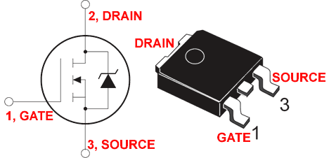
                          Here is a diagram for anyone unfamiliar with this - almost all mosfets have this reversed diode in it from source towards gate back towards the positive of the power supply:


                          Does your mosfet have the reversed diode or not? I know it doesn't make a difference in your overall example, but I think it is helpful to know specifically.

                          And I said that IF the other side IS loaded, then a difference may be seen on the primary battery by putting a scope across it. I just said there can be a comparison that can be seen to demonstrate where the spike is preferring to go. Obviously if the impedance of the load on the "cold side" is less than the impedance of the inductor, the spike will take that route and nothing will be pulsed back to the primary.

                          So based on your diagram, if you put a low impedance battery there on the output on the "cold side", the battery of course will receive the spike and it will charge it. But if you put an inductor on that output side and it is a higher impedance than the coil on the mostfet, that spike will never go to the load, it will go back to the battery - if the mosfet has the reversed diode in it that is.

                          With a transistor, you can guarantee that the only path is to the load on the "cold" side when it is switched off.

                          Anyway, I'm not disputing your claims about what happens on the "cold" side - this is all for clarification.

                          So far, do you agree with all the above? This doesn't get to what happens on the "cold" side yet but I think helps set the stage - at least for me to understand what you're doing.
                          Sincerely,
                          Aaron Murakami

                          Books & Videos https://emediapress.com
                          Conference http://energyscienceconference.com
                          RPX & MWO http://vril.io

                          Comment


                          • #43
                            Originally posted by Dave45 View Post
                            I agree, cold is better if we can manage it, and it will run our appliances.
                            evidently you have managed to capture it, as seen in your vids

                            We are anxious to see what further developments you have made

                            Thank You for revealing what you have discovered,
                            dave
                            My pleasure Dave,

                            She is a beautiful thing, and I am fascinated with her, for so many years we have been running just into so hot temperatures...that it was about time to get a bit 'colder'...to allow "Her" to give Us all, a bit of change, some fresh and cold air...We need it.
                            Now, related to 'Running all our appliances' I have a bit of disagreement on that...She does not like the sudden or constant crashes, just because she travels so fast... .

                            Thanks!

                            Ufopolitics
                            Principles for the Development of a Complete Mind: Study the science of art. Study the art of science. Develop your senses- especially learn how to see. Realize that everything connects to everything else.― Leonardo da Vinci

                            Comment


                            • #44
                              vids

                              Originally posted by Dave45 View Post
                              I agree, cold is better if we can manage it, and it will run our appliances.
                              evidently you have managed to capture it, as seen in your vids

                              We are anxious to see what further developments you have made

                              Thank You for revealing what you have discovered,
                              dave
                              I just saw this: RADIANT FREE ENERGY - YouTube

                              Not sure if this is part 2: http://www.youtube.com/watch?v=XyTRX8IfJQY but youtube removed it for music copyright violation. Looking forward to seeing it.
                              Sincerely,
                              Aaron Murakami

                              Books & Videos https://emediapress.com
                              Conference http://energyscienceconference.com
                              RPX & MWO http://vril.io

                              Comment


                              • #45
                                Originally posted by blackchisel97 View Post
                                @Ufopolitics Thank you for explanation. I ran couple tests and observed circuit behavior in resonant state. I tried incandescent bulb, as well as bulb in series with battery (just to try out some ideas).
                                My output freq. during first test was 13.5-15kHz, which I found to be the best resonant spot at lowest input A and best charging rate. I mainly rely on my scope reading. Transistor remains cold. I'll try to find my ultra fast diodes hiding from me but not sure if they're rated that high.
                                I'm curious about the different oscillator you have mentioned.


                                Vtech
                                Hello Blackchisel!!

                                I am so glad you did the test and it gave you positive results!!
                                Now, I know you like trying new ideas...but Radiant Energy does not goes too well inside of constant crashing, colliding electronic flow devices.
                                You will get much better results by using self ballasted fluorescent, they close just at start and the once Hg and other gases get excited and lit, then they go off...and you could use them to monitor your signals and compare the Flashes with your read out in DSO.

                                The same as with a regular type Brushed DC Motor...since it is constantly switching they are ok...however , soon will be better Dynamo-electric machines that will perform even better with this type of beautiful electricity.

                                You got pretty high in output oscillations, however, should keep an eye on your other side also (Input)...so, please tune in slow...Incandescent, halogens, etc "demands" too much, that's why Radiant Energy went that high...but with a Fluorescent 125 W/120V...you will just need @ 2000 Hz in output...spending @800Hz (depending on your set-up)
                                Diodes are important not only as Fast switchers, but also as having lower resistance ratings at forward bias...
                                Also try to check your Amperage and Voltage at Input versus Output...at same times with a Load present at Cold side, a Load you know its spec's as W, V and I...and let me know.

                                Thanks!!

                                Ufopolitics
                                Principles for the Development of a Complete Mind: Study the science of art. Study the art of science. Develop your senses- especially learn how to see. Realize that everything connects to everything else.― Leonardo da Vinci

                                Comment

                                Working...
                                X