Announcement

Collapse
No announcement yet.

My Motors got me to Tap into Radiant Energy

Collapse
X
 
  • Filter
  • Time
  • Show
Clear All
new posts

  • Originally posted by Ufopolitics View Post
    Excellent!!


    Your Oscillator will work with those diodes...however, the 1N4148 are designed for that job Ian, so the heavy rectifiers are faster, but they will not "filter" (will leak small reverse currents) like a signal diode never, but the only thing that could be wrong in your circuit (due to not putting the signal diodes) would be a bit of a coarser signal when tuning the Pot to Hi-Lo frequencies...meaning, it may not render a clean signal ...but it will not cause any dramatic or severe damage to anything...except a "noise" in the switching...


    You could just use a small piece of cable and jump it through the outer contacts above the board, and not take the whole socket and remove soldering off...easier...

    Great!!


    Run a test without removing them, observe the behavior of output and lamp...basically at steady high frequencies(600-800)...and watch it does not keep blinking but a steady illumination, and Hertz do not vary too much.


    What do you mean by run a test with the 36V "without" mosfets??!!, I guess you are referring to check low frequency signal output from gates connection (leg3 of 555)?

    Yes that is correct, 50% duty cycle is fine...but the Pot to increase frequency must be at highest resistance...meaning, zero hertz at output then dialing slow...very slow up.


    Regards and good testing Ian


    Ufopolitics
    G'Day UFO et al

    I still can,t get it to work
    Up to the Oscillator works the duty cycle goes from .05 % to 99%
    The frequency is about .5khtz
    I tried a different coil 5 strands 580 feet of 0.8mm diam all in parallel
    1.32 Ohms still no results
    Tomorrow I will endevour to find what is the problem must be the wiring of the mosfets?
    Everything went cooler by about 1 deg
    Let you know results tomorrow
    Regards

    Comment


    • Originally posted by iankoglin View Post
      G'Day UFO et al

      I still can,t get it to work
      Up to the Oscillator works the duty cycle goes from .05 % to 99%
      The frequency is about .5khtz
      I tried a different coil 5 strands 580 feet of 0.8mm diam all in parallel
      1.32 Ohms still no results
      Tomorrow I will endevour to find what is the problem must be the wiring of the mosfets?
      Everything went cooler by about 1 deg
      Let you know results tomorrow
      Regards

      G'Day Again
      When I ran the machine I took some measurements Volts didn't make sense so I used another coil I had it is a 5 filar, 583feet each strand soldered the ends together so all were in parallel measured 1.32 Ohms still did not light the bulb Tried the bulb in the house socket it was OK

      When I was running the machine the voltages were as follows
      Battery 38.6v the Oscillator recieved always 12.4 v
      I measured @ 3 different duty cycles neg probe on Batt neg
      " 99% 50% 1.5% "
      "Oscillator Out 10.4v, 4.7v, 0.2v "
      "Source Bus 10.4v, 4.7v, 0.2v "
      "Gate Bus 10.4v, 4.7v, 0.2v "
      "Heatsink/Drain 38.6v, 38.6v, 38.6v "
      Across Load Pos and Neg
      "Before Diodes 0.0v, 0.0v, 0.0v "
      "After Diodes 2.8v, 1.9v, 1.6v "


      The bulb never even gave a flicker
      Regards

      Comment


      • Originally posted by torpex View Post
        What is the difference between the 555-8ma and a specific mosfet driver?
        Specific mosfet drivers are optimized in several properties for this dedicated task. They can source/sink for short time several amps in order to charge/discharge the gate capacitance suddenly -> this makes FETs fast for professional use.
        Imagine a flywheel. It can be accellerated and sustained with very few power (driver standby high or low state). In case of slipping a rod through the spokes it will generate extrodinary forces - for short time! (switching action)
        In order to keep our setups cheap and simple with readily available components we decided for LM393 and NE555 components (smaller flywheels). Some of us have no funds left for specialized components. A thorough tradeoff will give suffitient driver properties.
        In any case we are short of driving current for optimal drive. We need to spend this restricted ressource with minimum drawback. Therefore we can alter/optimize different parameters.
        • The worst driver is if we use one half of LM393 (16mA sink) with a pullup of 10K driving 6 FETS over long thin wires.
        • Improve by shorting the wires. And make all grouds out of thick wire!
        • In same range range is a LMC/TMC555 (8mA source / sink) Additional improvement by connecting "discharge" pin to output (= double sink capability).
        • It is even better if we use both halves of LM393 (32mA sink) in parallel with a common pullup of about 1K.
        • Improve drive capability by using a NE555 (200mA source/sink) Additional improvement by connecting "discharge" pin to output (= double sink capability).


        Same sequence starts again - but on a much higher performance if you decide to drive single FETs by an dedicated driver each being built in direct vicinity to the FET.
        Here a LMC/TMC555 might be OK because it is quite fast and will deliver its bit of current much earlyer than a NE555.

        So my hint is to build your driver (whatever setup you choose) from the oscillator separated. Then you have an interchangable building stone for your setup and you can multiply and play with them in order to get optimized results.
        If you are happy and own a scope then check the switching time of the FET while replacing the coil by a power resistor (no bulb - it behaves extremely non linear) and post the setup along with measured figures in order to help those with no funds.
        Experts spend hours a day in order to question their doing while others stopped thinking feeling they were professionals.

        Comment


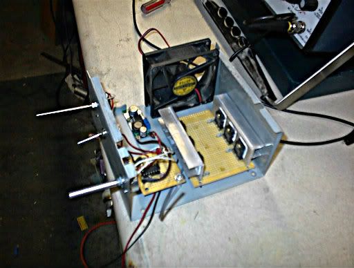
        • Some progress on my circuits.
          Last edited by larryross; 06-25-2012, 02:46 PM.

          Comment


          • Get It Running

            Kogs
            Here is some of the things we ran into when first starting went bad.
            1. We had the fets in backwords.
            2. Diodes were wrong type or backwords.
            3. Too much resistance at pots.
            4. It is vary hard to get it tuned in at first with less than 24 volts.
            5. Circuit is wired wrong or incomplete.

            When you first get a frequency signal thru the coil, (using a small CFL at first), lower the lights in the room. This will help you see a brief flicker in the CFL when you turm pots. It might at first, just flicker one time over the whole pot range and only when turning pot in one direction. Just get that pot that you are turning when you see the lite flicker close to the point where it flickered and stop. Then turn the other pot untill the lite comes a little stronger and longer. Keep going back and forth with each pot untill you wiggle your way to a brighter lite. Once you get the light worked up you can then adjust voltage up or down and when you turn on the switch, it will self start and go from there. It seems as thou when first getting it to run you must work for it but after the circuit has been set up better and run several times, it self starts.
            Dana
            "Today's scientist have substituted mathematics for experiments and they wander off through equation after equation and eventually build a structure which has no relation to reality."
            Nikola Tesla

            Comment


            • Hello Larry

              Originally posted by larryross View Post
              Some progress on my circuits.
              Hello Larry,

              Nice set up!!...it is almost ready to be fired up!!

              Now, one thing I most tell you I am seeing at plain sight...in the pictures...

              You have the Drain-Sink of Mosfet's way too close to the metal chassis, basically in the back part, therefore, have to make sure it would be very well isolated from ground...or your N-Channel Mosfet's will die the minute you turn on circuit!...Unless you have isolated the Drain to Heat-sink and got Drain from legs of transistors...which is a kind of weaker and not recommended connection for mosfets of High Currents Voltages...I see some white something between walls on back mosfets...can't tell is insulation or the aluminum body.
              I always use the aluminum heat sink as Bus Bars to transmit Drain pulsed currents with heavy bolts-connectors.
              The other thing I recommend to all, is to ground the POT Body and the walls that hold them together, never to isolate them, because as you just touch them, even being plastic knobs...it will alter the frequency to sky high levels while tuning it.

              Other wise I see your set-up very well built Larry, excellent!

              Regards

              Ufopolitics
              Last edited by Ufopolitics; 06-25-2012, 05:34 PM.
              Principles for the Development of a Complete Mind: Study the science of art. Study the art of science. Develop your senses- especially learn how to see. Realize that everything connects to everything else.― Leonardo da Vinci

              Comment


              • Weak or No Source at all...

                Originally posted by iankoglin View Post
                G'Day Again
                When I ran the machine I took some measurements Volts didn't make sense so I used another coil I had it is a 5 filar, 583feet each strand soldered the ends together so all were in parallel measured 1.32 Ohms still did not light the bulb Tried the bulb in the house socket it was OK

                When I was running the machine the voltages were as follows
                Battery 38.6v the Oscillator recieved always 12.4 v
                I measured @ 3 different duty cycles neg probe on Batt neg
                " 99% 50% 1.5% "
                "Oscillator Out 10.4v, 4.7v, 0.2v "
                "Source Bus 10.4v, 4.7v, 0.2v "
                "Gate Bus 10.4v, 4.7v, 0.2v "
                "Heatsink/Drain 38.6v, 38.6v, 38.6v "
                Across Load Pos and Neg
                "Before Diodes 0.0v, 0.0v, 0.0v "
                "After Diodes 2.8v, 1.9v, 1.6v "


                The bulb never even gave a flicker
                Regards


                Hello Ian,

                "Source Bus 10.4v, 4.7v, 0.2v "
                It does not sound right...Source must be -38V?...If working on N-Channel Mosfet's Source Bus. But then it does not make sense at all to obtain at Drain Bus 38V??!!
                The other thing:
                Across Load Pos and Neg
                "Before Diodes 0.0v, 0.0v, 0.0v "
                You do not have Load power at coil at all Ian!!
                Check Positive to Coil with reference to Ground(Source).
                Check that you have transferred Ground (Source) wires from circuit to circuit boards with heavy and robust connections and are conducting well.

                Your problem is minimum, calm down and relax, you are almost there!

                Your problem lies on High Voltage Sourcing-Feeding of the 38 Volts side...Positive or Negative there...are not connected right or wire missing between circuit boards.

                Cheers and pleeease let Us know!


                Regards


                Ufopolitics
                Principles for the Development of a Complete Mind: Study the science of art. Study the art of science. Develop your senses- especially learn how to see. Realize that everything connects to everything else.― Leonardo da Vinci

                Comment


                • Originally posted by Ufopolitics View Post
                  Hello Larry,

                  Nice set up!!...it is almost ready to be fired up!!

                  Now, one thing I most tell you I am seeing at plain sight...in the pictures...

                  You have the Drain-Sink of Mosfet's way too close to the metal chassis, basically in the back part, therefore, have to make sure it would be very well isolated from ground...or your N-Channel Mosfet's will die the minute you turn on circuit!...Unless you have isolated the Drain to Heat-sink and got ADrain from legs of transistors...which is a kind of weaker and not recommended set up for mosfets of High Currents Voltages...I see some white something between walls on back mosfets...can't tell is insulation.
                  Good eyes, but if you look a little closer you will see the reflection off the clear plastic insulator I placed back there. The white stuff you see if thermopaste for better heat transfer.


                  The other thing I recommend to all, is to ground the POT Body and the walls that hold them together, never to isolate them, because as you just touch them, even being plastic knobs...it will alter the frequency to sky high levels while tuning it.

                  Other wise I see your set-up very well built Larry, excellent!

                  Regards

                  Ufopolitics
                  The pots are mounted on the case which is metal as you observed by the heat sinks. I have 10 turn pots on order for finer tuning. When completely finished all will have a common ground.

                  Has anyone that is replicating this achieved verifiable radiant yet?
                  Thanks for your input UFO.

                  Regards
                  Larry

                  Comment


                  • Ian Koglin and All

                    Hello Ian,

                    Ok, in this picture below, I see things that are not correct...but then again, I may be wrong...

                    http://i1193.photobucket.com/albums/...s/IMG_0653.jpg

                    And I can not tell which is Positive which is negative...

                    Ian and All others replicating this:

                    Please use color code wiring for electrical connections, do not mix Red with Green, Green is always ground, Red is always Positive. Bright Reds, Orange and Yellows are used for positive, or positive signals...Green, Black...even sometimes Blue are used for grounds or Negatives.
                    Make sure when you take a shot, a picture of your set-up, you do not have hidden wires that leave the "scene" or "Area of View" and can not be traced at simple sight by looking at pic.

                    For example Ian, you have a red cable going to a connector (I don't know if next connector where another green wire comes out to mosfet board is connected through the plastic connector to that positive?...red?? Now that green passes through mosfet board under...have no idea if it is or not connected to board underneath...then goes to Coil wire...So, I can only "assume" you will connect the NTE576 in that plastic dual bolted conn..?

                    I also see a green cable coming out of mosfet's board (bolted) going to "nowhere, infinite"..maybe to Coil?...or is it just ground?

                    Mosfet's Board should only have three cables...

                    One is Source Negative direct to Source of Mosfet's legs.
                    Second wire for Drain, going to one Coil Terminal...then derive Diode -l>- to Lamp.
                    Third, is the Gate wire from 555 or LM339, or whatever oscillator you may have there...
                    Now according to your pic, I only see two cables going there, and that is assuming the under board running green cable (Positive?) from connector is going there also...
                    Now Positive (+) from Source, (Batteries +) have absolutely nothing to do at Mosfet's board...just Negative Source, Drain to Coil, and Gate from Oscillator.

                    Hope this post helps you trace your problem.


                    Regards


                    Ufopolitics


                    P.D: I know that those color codes that I mentioned above work basically for DC Electricity...As I know in AC the Black is the "Live Wire"...White is Neutral....and Green is ground from receptacles and embodiments chassis.
                    Last edited by Ufopolitics; 06-25-2012, 07:00 PM.
                    Principles for the Development of a Complete Mind: Study the science of art. Study the art of science. Develop your senses- especially learn how to see. Realize that everything connects to everything else.― Leonardo da Vinci

                    Comment


                    • Drain-Ground

                      Originally posted by larryross View Post
                      Good eyes, but if you look a little closer you will see the reflection off the clear plastic insulator I placed back there. The white stuff you see if thermopaste for better heat transfer.


                      The pots are mounted on the case which is metal as you observed by the heat sinks. I have 10 turn pots on order for finer tuning. When completely finished all will have a common ground.

                      Has anyone that is replicating this achieved verifiable radiant yet?
                      Thanks for your input UFO.

                      Regards
                      Larry

                      Great Larry!


                      However, you know that, am sure...It is BEST to use a Drain Bus Bar (the Heat Sink) to bolt there a solid pulsing Drain out to Coil, rather than from the finer mosfet leg...besides if mosfet gets extremely hot, could do ground through fine ceramic paper as insulation from factory...then Ka-Boom...they are gone...and...I know you do not like fires..till you build that Bunker...

                      I am used to build them like that because that is the way professionally built Motor Controllers are made...heavy Bus Bars as Drain Outputs...


                      Regards


                      Ufopolitics
                      Principles for the Development of a Complete Mind: Study the science of art. Study the art of science. Develop your senses- especially learn how to see. Realize that everything connects to everything else.― Leonardo da Vinci

                      Comment


                      • Hello Dana!!

                        Originally posted by prochiro View Post
                        UFO
                        It seems that using the tape style of 2" carbon (which has its own covering) can be rolled over the core like a traditional wind and then the copper primary can be rolled on next which brings them even closer togeather. This works the same as long as the diodes are in place. One funny thing is that if you set up the coil that way, putting the intercore coil in does nothing.
                        Dana

                        Hey Dana!!


                        Great results with CF!!
                        Sorry I did not get back at ya before!...was busy arguing...
                        CF has some properties We have no idea how far it will take Us all...
                        I wrote it before...CF is like a Superconductor for RE...
                        I have done some testings that are not "possibles" in our Classic Physics...
                        I conducted the DR Chong Negative Resistor CF Test, as per J Naudin Labs Testings...mine also gave negative resistance values...so this is a fact, CF is a Negative Resistor.
                        I have wounded magnetic wire around a Hollow Cylinder Mesh of Carbon Fiber...I get absolutely nothing as Radiant Output...and it is not touching anything...as a matter of fact I used tape between wire and CF...

                        The other test...is just to get your terminals with Radiant output...while bulb is lighting up...then just "touch" a CF Mesh...with or without resin...don't matter...Radiant will go away like magic...bulb will turn off...no Radiant Power even after you not touch the mesh anymore...can't restore the system...by just releasing terminals...must start all over again...She's gone!!

                        And more tests I have done on this...is fascinating!


                        Regards


                        Ufopolitics
                        Principles for the Development of a Complete Mind: Study the science of art. Study the art of science. Develop your senses- especially learn how to see. Realize that everything connects to everything else.― Leonardo da Vinci

                        Comment


                        • HID lighting

                          Originally posted by Ufopolitics View Post

                          ...and some extreme lighting like the HID Bulb I have a video on...it takes 1 to 1.5 amps out of the Six point three (6.3 Amps) batteries have
                          UFO,

                          I have been following along for awhile, but still haven't had any free time to build anything yet. Your comment above really caught my attention. I am extremely interested in seeing your video with the HID lighting.

                          Is that something you will be posting soon?


                          Many thanks,

                          Brent

                          Comment


                          • HID Bulb Video

                            Originally posted by BrentA929 View Post
                            UFO,

                            I have been following along for awhile, but still haven't had any free time to build anything yet. Your comment above really caught my attention. I am extremely interested in seeing your video with the HID lighting.

                            Is that something you will be posting soon?


                            Many thanks,

                            Brent
                            Hello Brent,

                            That video has been on my channel for a while...

                            But here it is a direct link...

                            LIGHTING HID BULB ASSY WITH RADIANT ENERGY - YouTube

                            Regards


                            Ufopolitics
                            Principles for the Development of a Complete Mind: Study the science of art. Study the art of science. Develop your senses- especially learn how to see. Realize that everything connects to everything else.― Leonardo da Vinci

                            Comment


                            • Originally posted by Ufopolitics View Post
                              Great Larry!


                              However, you know that, am sure...It is BEST to use a Drain Bus Bar (the Heat Sink) to bolt there a solid pulsing Drain out to Coil, rather than from the finer mosfet leg...besides if mosfet gets extremely hot, could do ground through fine ceramic paper as insulation from factory...then Ka-Boom...they are gone...and...I know you do not like fires..till you build that Bunker...
                              Yes UFO I don't have all the wiring done yet. Drilling and taping the heat sinks for fet drain is still not done yet as neither is the 36V and ground connections or the fet driver lines. Still much to do.

                              I am used to build them like that because that is the way professionally built Motor Controllers are made...heavy Bus Bars as Drain Outputs...


                              Regards


                              Ufopolitics
                              Yes that is common practice and I did that on all devices that need cooling in all the industrial controllers I designed and built, but thanks for the reminder.

                              Regards
                              Larry

                              Comment


                              • LiPo Dare Devil

                                Ufopolitics
                                I am not afraid of LiPo's Larry...I have run them to a point of heating up and swelling like balloons ...hahaha...however, nothing happened so far as getting on fire or exploding, I have also taken them apart, take the bad cells off and make up a new set by exchanging cells from other battery...and soldering with a 75 Watt soldering iron I have for those purposes. ..At the Hobby Shop where I buy them, they offer me to get one of those "explosion proof" bags...I never use them...so they call me "LiPo Dare Devil"...
                                UFO - You are a worry .. LiPo's must be treated with respect and not abused - A good friend of mine badly burned his new home and was lucky to avoid injury by not obeying the rules. We need your expertise here, so stay safe

                                JohnStone.. Thank you for your recent circuits and explanations. Your attention to detail is amazing.

                                Larry.. Keep asking questions - we all benefit from the answers .. Being an aeromodeller, you obviously are a good guy. Stay well.

                                Comment

                                Working...
                                X