Announcement

Collapse
No announcement yet.

My Motors got me to Tap into Radiant Energy

Collapse
X
 
  • Filter
  • Time
  • Show
Clear All
new posts

  • Originally posted by prochiro View Post
    UFO
    It seems that using the tape style of 2" carbon (which has its own covering) can be rolled over the core like a traditional wind and then the copper primary can be rolled on next which brings them even closer togeather. This works the same as long as the diodes are in place. One funny thing is that if you set up the coil that way, putting the intercore coil in does nothing.
    Dana
    Greetings Dana
    I know you probably won't answer, but I am very interested in where you got the pre-covered carbon fiber tape... I have searched the net and haven't found anything. A 1/4 inch 6mm wide coated CF tape would be perfect. Are you sure the coating is electrically insulating?

    Larry
    Last edited by larryross; 06-27-2012, 12:30 AM.

    Comment


    • Ian
      Keep in mind that if you have a coil with a 1 Ohm (that is almost a direct short) resistance and you hook 36V across it, it can pull up to 36 Amps. The coil would have to be wound with 6AWG wire to handle it at DC. With the way the circuit is built there is no way you can hook 36 volts across it (turn on FET) without pulsing it with a very short low frequency duty cycle (like maybe 10Hz and 5% on duty cycle or less if possible) without smoking something. The FET array can handle max 750W + some for heat sink maybe 1000W total.

      Did you check the out put of the fets before you hooked up the coil?


      Regards
      Larry

      Comment


      • CF coil

        UFO,

        I can't spend the time right now to tell you all the stuff that I have done lately, but I will get back to you in detail in hopefully in a day or two.

        I posted pics in Photobucket, one of which is a commercially made (in Russia) spark gap bulb a little bigger than a NE-2 glowing purple.

        I found that if I feed BOTH ends of the CF coil to one leg of an NE-2 and ground the other leg to me or a free-standing coil it glows. Then if I moved the ground to the Neg Output of the UFO device BOTH the NE-2 and the neon that I have on the Output get brighter.

        Then if I ground the Neg. Input to a free-standing coil the output of the CF coil increases from, say, 86v to 130v...about 50%.

        Gotta go,

        Bob

        Comment


        • Pancake coil

          Originally posted by larryross View Post
          Hi all
          Has anyone ever tried using this for multifilar winding. This is 16 wires X 100', but it is only 28 AWG. I have more than 400 feet of it. Thoughts come back 10 4?

          Regards
          Larry

          G'Day Larry
          Try this

          DMR 12 Tranny energizer pictures by Kogs1 - Photobucket

          DMR Lives in Aus and is a member of BM forums he posted these detail Oct 2 2010
          10 4 are you a ham radio operator?
          Regards

          Comment


          • Checking Fets

            Originally posted by larryross View Post
            Ian
            Keep in mind that if you have a coil with a 1 Ohm (that is almost a direct short) resistance and you hook 36V across it, it can pull up to 36 Amps. The coil would have to be wound with 6AWG wire to handle it at DC. With the way the circuit is built there is no way you can hook 36 volts across it (turn on FET) without pulsing it with a very short low frequency duty cycle (like maybe 10Hz and 5% on duty cycle or less if possible) without smoking something. The FET array can handle max 750W + some for heat sink maybe 1000W total.

            Did you check the out put of the fets before you hooked up the coil?

            Regards
            Larry
            G'Day Larry
            Please how do you mean to check the output do you mean with a DMM? across the source/Drain and Gate /Drain?
            Any imfo as to testing would be appreciated.

            Also what Oscillator are you implementing?

            BTW it is now 10:53 am Wednesday here
            Regards

            Comment


            • Bobs Oscillator

              G'day BoB and Dana
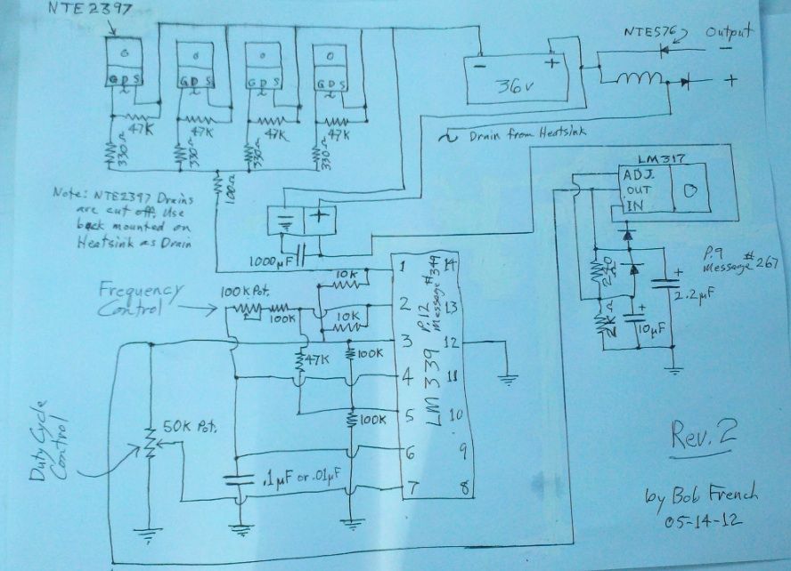
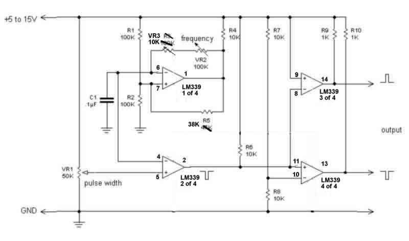
              Is this the Oscillator you are both running


              I thought that you were having trouble with it
              Regards

              Comment


              • Cst

                Larry
                Sure I will answer, I like the NEW less negative Larry. The company we are getting it from is an all woman company (CST - The Composites Store, Inc.) Narrow Unidirectional Carbon Fiber | Page 1 of 1. Im not sure how thick it is, maybe 1/16 inch and it comes in 1 inch and 2 inch wide. It has a covering that works well to isolate and can just be rolled on or in the core. It comes in 4,12 and 300 foot rolls. The cost for a 300 foot roll of 2 inch is 245.00 but Bob has been doing his testing with the 12 foot 2 inch and that is 20.00. I felt that our results were good enough that we needed to test further so I ordered a 300 footer so we could try longer lengths as it it not a good idea to splice this stuff. We are just getting our feet wet in carbon and have a list of testing we plan to do once all the stuff gets here. Bob is doing overtime at work this week and I am slow and steady but we plan on getting our next tests set up over this next weekend.

                Side Note: John Stone has given a PDF on his PWM and has recommended that if you are happy with your current setup that you not do his. I was happy with my setup but thought that if we are going to go ahead with this pulsing thing that the better control we have and the more sturdy setup we have, so much the better. I aggree with John about each making there oun choice but will have to say that that setup is presented in such a way that anyone can build it and repair it if neccessary and it is upgradeable. It will also, set up this way, pulse any circuit saving repeated construction. I am happy that I made it, actually three, each setup better and the third is in its own case which keeps it out of the way and able to power up anything due to the three differant driver/booster types he gave. I put small switches in instead of the rotory on my last one for the frequency caps and would note that you are not limited to four selections of frequency ranges. One can build most of it on strip boards and have little wire to mess with. Everything is cool and although I put a fan in the box, none is needed. I also used heavier transistors and found that this somehow gives better control.
                Dana
                Last edited by prochiro; 06-27-2012, 04:15 AM.
                "Today's scientist have substituted mathematics for experiments and they wander off through equation after equation and eventually build a structure which has no relation to reality."
                Nikola Tesla

                Comment


                • Ian

                  This is what Bob put together from all the posts as his guide. Note that on the drawing that he put referance to the page he got each area from. I would also use the posted page as another referance to better understand it all. We have driven from two to six fets with it. What I myself will be doing is using the above mentioned driver from John Stone to drive the fets. It does not matter what you drive them with as long as it is accurate and strong enough to do the job. We are all feeling your stress with getting your setup running but in the end, it will be worth it.
                  Dana
                  "Today's scientist have substituted mathematics for experiments and they wander off through equation after equation and eventually build a structure which has no relation to reality."
                  Nikola Tesla

                  Comment


                  • Originally posted by iankoglin View Post
                    G'Day Larry
                    Please how do you mean to check the output do you mean with a DMM? across the source/Drain and Gate /Drain?
                    Any imfo as to testing would be appreciated.

                    Also what Oscillator are you implementing?

                    BTW it is now 10:53 am Wednesday here
                    Regards
                    Ian
                    You will have to hook a different load on the fets and use a scope to see if you have pulses out to match the oscillator input. Load could be a 150 Ohm 10 watt power resistor. Also when you are doing that, check the time on voltage on the gate of the fet with a scope. Hmmm I forgot what problem you were having.

                    I am using the LM339 with dual complimentary output.


                    I know you guys down there see tomorrow before we do.

                    No not a ham operator, just wanted to through something new in.

                    Excuse my ignorance, but what is a tranny energizer? What could I do with it if I built one?

                    Regards
                    Larry

                    Comment


                    • Originally posted by iankoglin View Post
                      G'Day Again
                      When I ran the machine I took some measurements Volts didn't make sense so I used another coil I had it is a 5 filar, 583feet each strand soldered the ends together so all were in parallel measured 1.32 Ohms still did not light the bulb Tried the bulb in the house socket it was OK

                      When I was running the machine the voltages were as follows
                      Battery 38.6v the Oscillator recieved always 12.4 v
                      I measured @ 3 different duty cycles neg probe on Batt neg
                      " 99% 50% 1.5% "
                      "Oscillator Out 10.4v, 4.7v, 0.2v "
                      "Source Bus 10.4v, 4.7v, 0.2v "
                      Oscillator is probably right. except that at 1.5% duty cycle you don't have enough volts to turn on the fet.
                      Source is ground and should read 0 any time.

                      "
                      Gate Bus 10.4v, 4.7v, 0.2v "
                      "Heatsink/Drain 38.6v, 38.6v, 38.6v "
                      Across Load Pos and Neg
                      "Before Diodes 0.0v, 0.0v, 0.0v "
                      "After Diodes 2.8v, 1.9v, 1.6v "
                      gate looks right except again not enough volts to turn on fet.
                      drain looks right.
                      volts before and after diodes are all wrong. I am not sure what you mean... before and after both diodes or which diode?


                      The bulb never even gave a flicker
                      Regards

                      Comment


                      • Kogs new setup

                        Originally posted by larryross View Post
                        Oscillator is probably right. except that at 1.5% duty cycle you don't have enough volts to turn on the fet.
                        Source is ground and should read 0 any time.

                        "

                        gate looks right except again not enough volts to turn on fet.
                        drain looks right.
                        volts before and after diodes are all wrong. I am not sure what you mean... before and after both diodes or which diode?
                        Where the coil terminates at the output to the load there is a fast acting diode


                        This stops the Hot energy and only allows the Radiant energy

                        Regards

                        Comment


                        • Kogs new setup

                          Originally posted by iankoglin View Post
                          Where the coil terminates at the output to the load there is a fast acting diode


                          This stops the Hot energy and only allows the Radiant energy

                          Regards
                          PS

                          Perhaps I could try it with only 1 or 2 Mosfets as it is very expensive destroying 6 at a time

                          Kogs

                          Comment


                          • Hi all,

                            There are other questions in this schematic:


                            It is correct the value of R4 resistor to 10k? This sets the output, right?

                            It is correct the value of R1 resistor to 1k and R2 to 18K? If this is so the input current is too limited.

                            How do you set the frequency? Because VR is to adjust the pulse width, right?
                            This setup run with frequency fixed around 529 Hz and only adjust pwm (i think).


                            Regards
                            http://Cacharreo.com.es/foro

                            Comment


                            • Ian
                              I see 2 fast acting diodes that terminate with the coil... one on the + side and the other on the - side of your coil, to which are you referring to?

                              Also I would wire your on/off switch in to the + wire not the negative wire... this way when you turn off the switch the whole circuit is disconnected from the batteries. The way you have it, the while circuit is still connected to the battery when the switch is off. If you chose not to change it, I would disconnect the positive wire when working on it just to be safe.

                              I would also kick up your 12V supply to 13 or 14 volts... you can go to 15V and not hurt the 555. and find a way to boost your oscillator circuit output. Any thing lower that 4 volts going to the fet gate will not turn it on.

                              Wait... are you measuring the gate voltage with a DMM? That won't tell you what the turn on voltage is, because it will average the on time and you will get an average voltage instead of the turn on volts.
                              Yours is interesting, because if I look at the signal out of my oscillator the square wave signal is always 10V to 12V through all duty cycles looking at it with my scope.

                              Hope some of this helps.

                              Larry

                              Comment


                              • Originally posted by iankoglin View Post
                                Perhaps I could try it with only 1 or 2 Mosfets as it is very expensive destroying 6 at a time

                                Kogs
                                Hi Kogs,
                                It's the best, with a single MOSFET.
                                Recalls that already discussed, you can even use other cheaper model to try.

                                We must learn to start the circuit, because according to the settings ... can be forced and burn. Even if everything is correct.

                                I use the dmm in 10 AMPS DC mode to control the drain current. No switch to test, only probe to negative.
                                An example of my setup with 9w bulb for test:
                                Start and pots to 0: 0.02-0.03 A
                                Pot PW (this is a dangerous) up slowly to 0.5 A, the bulb flashes or lit.
                                Pot FR (frequency) this affects less than PW.
                                If there are readings of more than 2-3 amps is a sign that something is wrong, disconnect and check.

                                Good luck


                                Regards
                                http://Cacharreo.com.es/foro

                                Comment

                                Working...
                                X