Announcement

Collapse
No announcement yet.

My Motors got me to Tap into Radiant Energy

Collapse
X
 
  • Filter
  • Time
  • Show
Clear All
new posts

  • John G

    I have used the liquid plastic/rubber for many things and just feel that it would be hard to keep it from sagging until dry. I have thought of doing it with the tow straight up which would coat well but height would prohibit enough time for drying befor it touches anything or a thin spot might develope. The heat shrink is cheap and has a total coverage. Getting it thru is a pain but once in the wire is rock solid and can be wound as per copper several times. The tape style has a good covering and is ready to wrap. 300 feet of one inch is 117.00 and can be raped side by side to give three coils on a three inch core. Bob has good results with even 12 feet of two inch which is 20.00 out the door, ready to rap. I do not know now what effect the thicker coating would do. I do know that the more space (she) has, the happier she is and I think like a large battery, it holds more and gives more. Testing will be necessary to really know just how much. We do know that an additional coil in series with the CF produces twice as much and like I said, more space for her to live.

    To all having trouble with circuits.....
    You guys seem to have trouble with the voltage regulator and frequency/duty cycle. The correct answer is in looking at John Stones circuit and using that part of his system to slip into the rest of your circuit. That part of the system is simple and has correct diagram and values that once installed will not be hot or make smoke and is duty cycle from 1 to 99%
    Dana
    Last edited by prochiro; 06-27-2012, 05:02 PM. Reason: spelling
    "Today's scientist have substituted mathematics for experiments and they wander off through equation after equation and eventually build a structure which has no relation to reality."
    Nikola Tesla

    Comment


    • Torpex...

      Originally posted by torpex View Post
      Hi all,

      I've been checking the original ufo circuit in protoboard, without LM317, directly to 12v:


      Works ok
      Lit the 9w bulb with 12v only.
      Maybe a little less effective than the others.

      Unfortunately I have problems with my frequency counter. These are the readings that I have obtained with mosfets disconnected:
      Pot 0: 501 Hz
      Pot 1/2: 454 Hz
      Pot full: 497 Hz
      Also in 0 to 1/2 range: 0, jump to 110, climb to 454 in abrupt steps (little trimpot).
      I tried with a 12v bulb and an npn transistor in 'visual mode', lit gradually from 0 to 100%.
      I think it is a displacement of frequency of the 555 in pwm mode.

      Using other oscillators I hear the coil when changing the frequency.


      @Ufo
      My problem is that efficiency is approximately 80-85%, when I put more load also I have to raise the drain current proportionately.
      I've only tested up to 70W load

      Still do not know if this is the radiant, but if so, the question is:
      What I can do with it?


      Hello Torpex,

      Please follow Larry's advice "religiously" on all his recommendations to achieve best results.
      Your Pot must be Linear, not audio, not any other cheap that could jump or not be precise and accurate.

      Bread boards I also never used them at all...not good, agree with \Larry 100%

      Now...

      Still do not know if this is the radiant, but if so, the question is:
      What I can do with it?
      I can not believe you are asking this...after you have been here for so long...

      Being able to "tap Radiant" is a great step and achievement into future developments of "things" you could not even conceive or think off in its entirety...
      Radiant can be re-converted into Hot at very high levels...
      Radiant could cure Cancer and many other illness so far considered as terminal...
      Radiant is Free Energy, by spending 'nickels and dimes" we get millions...

      and many, many more...

      However, I am now more concentrated on Hot machines, Symmetry...I have devastating proof, and evidence with enough grounds to destroy all -up to now- story tellers about BEMF or CEMF...as we all know about it for the last 132 years...
      Conversions of Symmetric to Asymmetric Machines and all the "How to's" will be here soon...

      Watch me...


      Regards


      Ufopolitics
      Principles for the Development of a Complete Mind: Study the science of art. Study the art of science. Develop your senses- especially learn how to see. Realize that everything connects to everything else.― Leonardo da Vinci

      Comment


      • Originally posted by Ufopolitics View Post

        Conversions of Symmetric to Asymmetric Machines and all the "How to's" will be here soon...

        Watch me...


        Regards


        Ufopolitics
        UFO


        Pictures are worth a thousand words even smillies.

        It's getting closer... I can hardly wait.

        Regards
        Larry

        Comment


        • Hi All
          Here is where I got my 10 turn linear pots. They say 2 for $8.99 with free shipping, but they actually sent me 4 instead.

          2PCS Multi-Turn Wirewound Potentiometers WXD3-13 100K OHM | eBay

          Hope this helps
          Larry
          Last edited by larryross; 06-27-2012, 09:03 PM.

          Comment


          • CF coil

            UFO et al,

            OK. I think we have made some good progress on the CF coil. I will try to give a detailed report here.

            I wound the 2" CF tape at the middle of a spool that is about 5.5" all and has a 3" hole in the center. I simply wound the 12' of CF tape onto the spool then wound a coil of 4 magnet wires, each 300' long, Litzed, 19AWG starting at the top of the spool, down over the CF tape, to the bottom then back up, and down again, keeping the coils as close and even as possible. With the 4 copper wires in parallel the impedance measured .8 ohms.

            I also wound a CF coil using 7 strands of 1k CF tow, each 15' long, covered w/ 3/64" heat shrink tubing, all in parallel. I initially thought that tho coil was working well, but later discovered that one of the strands was in fact touching the other coil on one end and that at least 90% of the power was coming from the 2" CF tape coil. I took this 1k tow coil out of the test and the 2" tape coil provided very well...for starters at least.

            I previously posted numbers of volts per input and don't have that info in front of me at the moment, but the interesting phenomenon is worth noting here.

            In my first test I couldn't measure any voltage, but in this second test I placed diodes on the CF tape coil ends to make the energy go one direction. I assume that this only affects the Hot energy, but I was able to measure DC voltage. I think that by doing this I am probably only measuring 1/2 the actual volts. And when I attach both ends of the CF tape coil to the same leg of a NE-2 and it's other leg to a ground it does light a little brighter than with just one end of the coil attached. I used a free-standing coil (not attached to the circuit at all or to any thing else) to ground the NE-2. If I touched it on the ground side it got brighter, so I am a better ground than the coil (there's probably a joke in there somewhere). Dana and I discussed the probability that a really good ground to the earth would increase the energy even more.
            I also wonder about attaching an antennae to the center of the coil (?). It might increase things from the other end. (?)

            The next thing is that I attached the NE-2 ground leg to the Neg of the Output of the circuit. This produced greatly more energy as the NE-2 and the Neon that I was running on the circuit Output BOTH lit brighter!!! Here again both ends of the CF tape coil were attached to one side of the NE-2 and the other side to the Neg of the Output.

            I tried a commercial spark gap bulb that I had laying around. It is a little bit bigger than an NE-2, sealed glass bulb, and it glowed purple. I don't know anything about this spark gap bulb because it is all written in Russian. But it is a lovely purple.

            Next I attached the Neg input to the free-standing coil (as the NE-2 was now attached to the Neg of the Output) and the voltage measured from the CF tape coil jumped up about 50%. At the time it had been 84v and it went to 130v. Again, this is measuring through the diodes and may be 1/2 of what's there. (?)

            Also, I was able to turn off the device, then start it back up w/o turning the pots down to achieve low Hz. The device immediately produces at any setting.

            Dana has told you about our next tests. I am going to make a coil using 50k tow in heat shrink wrapped around a 1/2" spool and filled out about 1/2"-3/4" thick, then wrap 2 strands of 19AWG, each 125' long (maybe 4 strands and keep them separated, 2 and 2 so I could bring a pair off a MOSFET separately to keep the ohms around .8-1 ohm). Dana and I are very impressed with 150' of 18AWG as a coil. It seems to create a good strong magnetic field. I think we need to experiment with coil wires as short as 50'. (?)

            If I remember anything else I will post it with the results of the next tests. I have some pics at:

            Pictures by bobfrench - Photobucket

            Bob

            Comment


            • Hi All
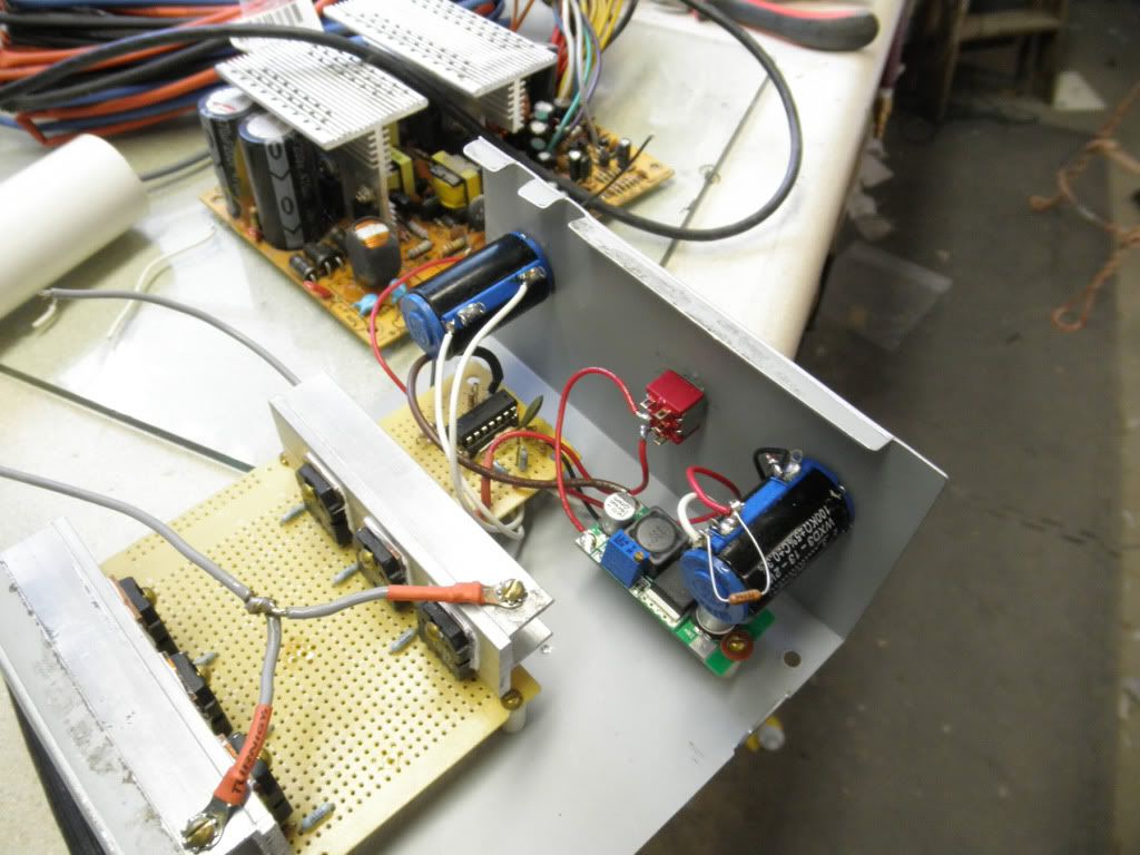
              My post isn't nearly as exciting or interesting as Bob's, but thought I would share a pic of my setup with the new 10 turn pots. Man it is sweet to be able to fine tune the frequency and duty cycle.
              Frequency range is 25Hz to 20KHz. It does have a problem though... from 25Hz to 5KHz the duty cycle stays the same all the way through, but above 5KHz the duty cycle changes and gets less on as the frequency increases so I need to keep changing the duty cycle to increase the frequency. I am sure I will be able to fix it in time, but with the frequencies we have used up to now it should be fine for now.

              Regards
              Larry

              Comment


              • Pots

                Larry
                Those pots do look vary nice and are large enough that they should hold up well. Your set looks solid and I am guessing you have a cover that when installed will keep it cool and clean.
                Dana
                "Today's scientist have substituted mathematics for experiments and they wander off through equation after equation and eventually build a structure which has no relation to reality."
                Nikola Tesla

                Comment


                • Nice Larry!!!

                  Originally posted by larryross View Post
                  Hi All
                  My post isn't nearly as exciting or interesting as Bob's, but thought I would share a pic of my setup with the new 10 turn pots. Man it is sweet to be able to fine tune the frequency and duty cycle.
                  Frequency range is 25Hz to 20KHz. It does have a problem though... from 25Hz to 5KHz the duty cycle stays the same all the way through, but above 5KHz the duty cycle changes and gets less on as the frequency increases so I need to keep changing the duty cycle to increase the frequency. I am sure I will be able to fix it in time, but with the frequencies we have used up to now it should be fine for now.

                  Regards
                  Larry


                  Hey Larry!!

                  That looks awesome, excellent!!...Almost ready to go.

                  ... Man it is sweet to be able to fine tune the frequency and duty cycle.
                  Are you rubbing me with the fact you could change duty cycle now, Larry?...
                  Is Ok...is ok...

                  I don't think that the 5Khz deal is a big issue...and sure you could fix it...however, am sure it will run better than mine... Grrr

                  Regards

                  Ufopolitics
                  Principles for the Development of a Complete Mind: Study the science of art. Study the art of science. Develop your senses- especially learn how to see. Realize that everything connects to everything else.― Leonardo da Vinci

                  Comment


                  • Impressive Bob!!

                    Originally posted by bobfrench@fastmail.fm View Post
                    UFO et al,

                    OK. I think we have made some good progress on the CF coil. I will try to give a detailed report here.

                    I wound the 2" CF tape at the middle of a spool that is about 5.5" all and has a 3" hole in the center. I simply wound the 12' of CF tape onto the spool then wound a coil of 4 magnet wires, each 300' long, Litzed, 19AWG starting at the top of the spool, down over the CF tape, to the bottom then back up, and down again, keeping the coils as close and even as possible. With the 4 copper wires in parallel the impedance measured .8 ohms.

                    I also wound a CF coil using 7 strands of 1k CF tow, each 15' long, covered w/ 3/64" heat shrink tubing, all in parallel. I initially thought that tho coil was working well, but later discovered that one of the strands was in fact touching the other coil on one end and that at least 90% of the power was coming from the 2" CF tape coil. I took this 1k tow coil out of the test and the 2" tape coil provided very well...for starters at least.

                    I previously posted numbers of volts per input and don't have that info in front of me at the moment, but the interesting phenomenon is worth noting here.

                    In my first test I couldn't measure any voltage, but in this second test I placed diodes on the CF tape coil ends to make the energy go one direction. I assume that this only affects the Hot energy, but I was able to measure DC voltage. I think that by doing this I am probably only measuring 1/2 the actual volts. And when I attach both ends of the CF tape coil to the same leg of a NE-2 and it's other leg to a ground it does light a little brighter than with just one end of the coil attached. I used a free-standing coil (not attached to the circuit at all or to any thing else) to ground the NE-2. If I touched it on the ground side it got brighter, so I am a better ground than the coil (there's probably a joke in there somewhere). Dana and I discussed the probability that a really good ground to the earth would increase the energy even more.
                    I also wonder about attaching an antennae to the center of the coil (?). It might increase things from the other end. (?)

                    The next thing is that I attached the NE-2 ground leg to the Neg of the Output of the circuit. This produced greatly more energy as the NE-2 and the Neon that I was running on the circuit Output BOTH lit brighter!!! Here again both ends of the CF tape coil were attached to one side of the NE-2 and the other side to the Neg of the Output.

                    I tried a commercial spark gap bulb that I had laying around. It is a little bit bigger than an NE-2, sealed glass bulb, and it glowed purple. I don't know anything about this spark gap bulb because it is all written in Russian. But it is a lovely purple.

                    Next I attached the Neg input to the free-standing coil (as the NE-2 was now attached to the Neg of the Output) and the voltage measured from the CF tape coil jumped up about 50%. At the time it had been 84v and it went to 130v. Again, this is measuring through the diodes and may be 1/2 of what's there. (?)

                    Also, I was able to turn off the device, then start it back up w/o turning the pots down to achieve low Hz. The device immediately produces at any setting.

                    Dana has told you about our next tests. I am going to make a coil using 50k tow in heat shrink wrapped around a 1/2" spool and filled out about 1/2"-3/4" thick, then wrap 2 strands of 19AWG, each 125' long (maybe 4 strands and keep them separated, 2 and 2 so I could bring a pair off a MOSFET separately to keep the ohms around .8-1 ohm). Dana and I are very impressed with 150' of 18AWG as a coil. It seems to create a good strong magnetic field. I think we need to experiment with coil wires as short as 50'. (?)

                    If I remember anything else I will post it with the results of the next tests. I have some pics at:

                    Pictures by bobfrench - Photobucket

                    Bob
                    Hello Bob!!


                    Awesome testing and findings Bob!!
                    Remember when I wrote that you will have very exciting "surprises" with the CF Coil?...well you've got them now, plus the ones to find out yet...

                    A very good ground is needed to increase power output, now related to "Air sector" your Russian Spark Gap Bulb so far is doing that job...That Purple plasma light is just pure concentrated Radiant Energy at work...very beautiful isn't it?

                    Nikola Tesla spoke about metal plates suspended high on roof of buildings or an specific structure tower...s tube...I have done the "Air Transmission" with Plasma Lamps and Open Spark Gaps...

                    Bob, wanted to tell you something to try...See if you could get a couple of High Voltage Caps, not Electrolytic, but Mica or something, Oil based will be best, Old Microwaves have them of High Frequency, and they almost never go bad...of EQUAL low values like 0.01 or .1 , then connect them at CF Coil, between both terminals...or between R-2 Leg to ground and the two terminals of CF. Try in parallel there and also in series with the Russian bulb (Spark Gap).
                    And also on Primary on the Radiant side... What this Caps will do is "Force" a resonance between Coils...It will create a bigger concentration of Radiant in your room, and please be careful!!

                    Radiant is "naive" as long as we are playing "small child's games", but, when attracting Her the right ways, and massively, (And neither one of Us...know when We could "ring the bell"...by making random connections) it will discharge huge loads down to everything you have connected there including You as Ground...She can go through almost everything we know off, except Carbon Fiber mesh...there She will die immediately. Note I said "Mesh", because a mesh, a Fabric, contains millions of short circuit carbon hair super-conductors where she will crash "iso facto".


                    Warm regards friend and Congratulations again !!


                    Ufopolitics
                    Principles for the Development of a Complete Mind: Study the science of art. Study the art of science. Develop your senses- especially learn how to see. Realize that everything connects to everything else.― Leonardo da Vinci

                    Comment


                    • Originally posted by larryross View Post
                      Hi All
                      My post isn't nearly as exciting or interesting as Bob's, but thought I would share a pic of my setup with the new 10 turn pots. Man it is sweet to be able to fine tune the frequency and duty cycle.
                      Frequency range is 25Hz to 20KHz. It does have a problem though... from 25Hz to 5KHz the duty cycle stays the same all the way through, but above 5KHz the duty cycle changes and gets less on as the frequency increases so I need to keep changing the duty cycle to increase the frequency. I am sure I will be able to fix it in time, but with the frequencies we have used up to now it should be fine for now.

                      Regards
                      Larry

                      G'Day Larry Looks very impressive
                      Please what circuit boards are you using to mount all your components?
                      Regards Kogs

                      Comment


                      • Originally posted by iankoglin View Post
                        G'Day Larry Looks very impressive
                        Please what circuit boards are you using to mount all your components?
                        Regards Kogs
                        Hi Ian
                        What is Thursday like?

                        These are general purpose circuit boards from radio shack. They have several sizes and trace patterns.

                        Here is a pic of the underside of the FET board.
                        http://i1267.photobucket.com/albums/...1/P6270098.jpg

                        Thank you all for the compliments on my setup. So far it works really well.

                        Regards
                        Larry
                        Last edited by larryross; 06-28-2012, 03:18 AM.

                        Comment


                        • Originally posted by larryross View Post
                          Hi Ian
                          What is Thursday like?

                          These are general purpose circuit boards from radio shack. They have several sizes and trace patterns.

                          Here is a pic of the underside of the FET board.
                          http://i1267.photobucket.com/albums/...1/P6270098.jpg

                          Thank you all for the compliments on my setup. So far it works really well.

                          Regards
                          Larry
                          G'Day Larry
                          It is a cold Thursday I hope you are not effected with the HUGE fire in Colorado I just saw it on the TV News

                          On my UFU machine I blew i Mosfet and I am going to remove/disconnect one of the strands in my coil this will of course increase the Ohms a bit

                          I am going to build a new Oscillator using the LM339
                          I was going to rebuild the Voltage regulator as I had wrong Diodes on it
                          Some 4 weeks ago I purchased this Voltage regulator and the instructions say max input is 36v My primary is actually 38+v would this be OK I do not know but the data sheet says the adjustable voltage is from 3v to 37v so it needs something like 1.2 to 3v to run it? probably it would handle it The schematic is here

                          LM317 variable power supply kit DIY + Video Instruction | eBay

                          If I use this one I could vary the input to increase the oscillator output
                          I will like you said test with the Coil removed with an appropiate resistor across the load Would I need to remove the diodes before the output to test as these diodes stop the Hot energy

                          Looking forward to see your machine run

                          Regards

                          Comment


                          • Originally posted by larryross View Post
                            ... from 25Hz to 5KHz the duty cycle stays the same all the way through, but above 5KHz the duty cycle changes and gets less on as the frequency increases so I need to keep changing the duty cycle to increase the frequency.
                            Hi Larry,

                            The facts mentioned below are not meant as criticism at all but should forward the notion that - depending on the actual circuit - it might give no success to fight against nonlinear behaviour of the duty cycle. Total simplicity suffers on certain drawbacks but I think we can live with this and it will not prevent any initial experiment.

                            I experienced such nonlinear behaviour if the circuit charges the corresponding timing cap via resistors. Then the voltage is not of true linear sawtooth shape but is bent depending on the value of the charging resistor (shark fin shape). So the following comparator chanages the duty cycle because it senses voltage and not time.
                            This behaviour can be minimized if the charge discharge rate is low (i.e. 0V....5V) while the charging resistor is being connected to a considerably higher regulated voltage i.e. 24V. In this case the resistor acts like a current source of moderate quality. (We make use of the mostly linear bottom part of the shark fin only.) The current simple circuits in this forum try to make use of high voltage at the timing capacitors being almost alike the supply voltage. This is the source of the effect mentioned above.

                            Exact this nonlinear behaviour was defended thoroughly by applying a simple current source (see my doc) for charging the timing capswhile running completely at 5V supply.

                            Please bear with me! Simple approaches are entirely SIMPLE BUT NOT USELESS.
                            rgds John
                            Last edited by JohnStone; 06-28-2012, 03:09 PM.
                            Experts spend hours a day in order to question their doing while others stopped thinking feeling they were professionals.

                            Comment


                            • Originally posted by iankoglin View Post
                              ..... max input is 36v My primary is actually 38+v would this be OK I do not know but the data sheet says the adjustable voltage is from 3v to 37v so it needs something like 1.2 to 3v to run it?...
                              The data sheet gives voltage above output voltage. So far it is OK.
                              Nevertheless we need to account for switch on conditions (output 0V and full charged cap after rectifier!!!! ) Dangerous!
                              Try a series resistor at input of your regulator. First guess try 50 Ohm - might be wrong. At switch on condition there will be suffitient voltage drop because the caps (discharged) around your regulator suck any electron (if there is such a pet out there - at all) available. A fat cap (100µF - guess) at regulator input will additionally help to delay the input voltage up to the time when the output voltage gets up.
                              Later on your driver circuitry will take few current and the voltage conditions will be OK for your regulator. The losses via the resistor are neglectable.
                              rgds John
                              Last edited by JohnStone; 06-28-2012, 01:02 PM.
                              Experts spend hours a day in order to question their doing while others stopped thinking feeling they were professionals.

                              Comment


                              • oscillator

                                johnstone,

                                Thanks for your circuit. As Dana mentioned, I found it to a be superior circuit.

                                It worked fantastic as a low side driver.

                                I am having a problem trying to connect an ir2101 mosfet driver, as cinan mentioned. I can't seem to get it to work right. First I blew mosfets, high first then the low, reconnected and fried the ir2101. It worked while connected to seperate mini lights, be fried when i hooked up coil.

                                I've been looking for 2 days and can't figure it out.

                                John, how would you connect an ir2101 to your comparator/driver to run a high low switch?

                                Thanks Thug

                                Comment

                                Working...
                                X