 Tweet
Tweet
Originally posted by prochiro
View Post
-
I don't think he could post if not registered... could he? -
Flea
For some reason, that diagram is missing. Here is a link to it.
Pictures by Prochiroone - Photobucket
Dana"Today's scientist have substituted mathematics for experiments and they wander off through equation after equation and eventually build a structure which has no relation to reality."Nikola TeslaComment
-
Hi Dana
Got the circuit .Thanks:
Hi Larry
Yes I do intend to replicate the circuit and others.It may be a challenge as I only have general knowledge of electrical circuits and nearly none of electronics.
Choice, nothing like a challenge and as they say who dares wins
Cheers
FleaComment
-
Just as idea:
I got today two uninteruptable PC PSUs from scrap. They contain all we need for further and more professional curcuits: case, heat sinks, cooling fan, battery compartment .....
If you see such units around put your hand on them for future use.
~o0o~
I tortured my brain in order to find out how a N-FET feels as high side driver in our very special setup.
FETs switch by an electrical field (voltage) at the gate in reference to the reference leg called "source".
I am convinced that our circuit with two FETs (up and down) can do with P-FET on high side only. This is because a P-FET get its voltage reference from the battery and this is stable at any condition. At same time P_FETs have their source leg at battery voltage as well. As member Ufo proved this is true because he owns a working setup.
If we use at top side a N-FET its voltage reference (source leg) is not the battery voltage but the upper side of the coil - a wild jumping beast in off state. And additionally - if the bottom FET is in off state we have no reference at all for the top FET. It can't work under this condition!
It's like writing on paper inside a running racing car. Save your FETs and money.
I never will try. I vote for opto drivers i.e. FOD3180 and for convenience I will build identical units as high and low side switches as well.
~o0o~Last edited by JohnStone; 06-30-2012, 11:08 PM.Experts spend hours a day in order to question their doing while others stopped thinking feeling they were professionals.Comment
-
fets/John Stone
John
You mentioned the upper fets earlier and I see that your working on it. If the upper is p-fet and referanced by battery, would we need the opto for protection or maybe not? Have you run some p-fets there yet to see? I wish I knew more about those things but it seems that we all will in time.
Dana"Today's scientist have substituted mathematics for experiments and they wander off through equation after equation and eventually build a structure which has no relation to reality."Nikola TeslaComment
-
Carbon Tow and Insulation
There seems not to be much on the net about carbon tow being used as a secondary coil and nothing about how to make it usable. Bob and I have been and are still working on that subject. I thought I would share a bit of what we found about getting the tow covered. This is not in any way saying you should or should not use carbon in your system, but if you want to try some here is how we made it. For 1K-5K you should use 1/16 heat shrink that comes in long rolls. Bob has put two 50K strands into 3/8 and that is a bit large but goes in easy. Now on the installation of the tow into the tubes. We have tried everything from air pressure to vacuum to thin wire and more. Bob first thought this up and it works. Take a sewing machine needle and tie some 8 to 12 Lb fishing line to it keeping the knot small.If the base of the needle will not go into the tube and be vary loose, take a dremmel and grind it thinner some. Place it into the tube, heave side first. I then took a hand full of 1/4 inch neo magnets and put them all together into a rod like. This makes the magnets stronger and is easy to hang onto. Slowly pull the needle through the tube and I mean slowly. If you go too fast you will loose your pull. The tube must be held very straight as any kink, twist, curve, ect, will be more resistance than you can pull. To help keep it straight while pulling I set a book over the tube with several inches sticking out. You must also keep the fishing line unspooled and in a straight line to the tube or you can not pull it. Pulling takes some practice and if you do not keep all items straight and place your body so the tube stays straight you will have problems. When pulling and everything is set up right, it will pull vary easy and vary fast, but, if you are pulling and feel even a slight change in pulling pressure or the magnet keeps pulling away from the needle, something is wrong. You must set your end down and go find out what needs adjusting at the other end or allong the tube. The angle you pull makes a big differance so play with it untill you get the hang of it. We have found that because of resistance, you should not try to pull thru more than 30 to 50 feet at a time. The tow will not be cut at the end but will be drawn thru the rest of the short tubes and then a larger heat shrink placed ofer the joints. Also be watchfull that when heating the tubes that you do not stretch them when hot as the increase in length will cause the tow to be pulled inside and you must then go find it. This does take some time at first but after several lines, you will get much faster. It is a good idea to have extra heat shrink handy because at first you may mess some up. I have tried to do this outside in the sun but had problems with the tube shrinking befor I got the needle all the way thru. Oh! I almost forgot, when the fishing line is thru, then tie it or better yet super glue it to the carbon and follow caution again when pulling it thru. Quality carbon can be purchased at CST. Google (CST carbon). Good Luck
Dana Last edited by prochiro; 07-01-2012, 02:20 AM."Today's scientist have substituted mathematics for experiments and they wander off through equation after equation and eventually build a structure which has no relation to reality."Nikola Tesla
Comment
-
p-fets
JohnStone or Dana,
The pfet works fine by itself as high side switch, like the nfet works fine by itself as a low side switch, to a point.
We are wanting hi/low switching at high voltages.
With the p-fet as a hi side switch and with the n-fet as a lo side switch, dual switch, as long as you switch a voltage less then or equal to the signal, it works great. hooked up with dual phase as mad scientist or john's with dual phase output.
The problem is that the p-fet does not shut off once signal voltage is less then the switching voltage, by much.
For pfet
(when signal is 0v) Vgs= Vg-Vs = 0 -(+24v)=-24v , therefore fet turns on
( signal is 12 v) Vgs= Vg-Vs = 12 - (+24)= -12v, therefore fet stays on
So, as long as you are switching more then signal you can't use pfet as is, by itself hi, or with an nfet lo.
Or, am I wrong.
Dana,
How much are you switching using a pfet on high side, whats your signal voltage?
A voltage shifter allows you to switch a somewhat higher voltage, but the Vg of the pfet must handle whatever you are switching, I've only switched up to 24v. But It worked really good.
But we need HIGH VOLTAGEswitching.
JohnStone,
I am going to get the opto's but I am sure the ir2101 will work. I think I might have figured out, what I did wrong.
I have 2 ir2101's left. Once they are gone, I will buy the opto's.
Also, john, I used an npn current mirror, instead of the pnp current mirror, for the current source, it seems to work vfine, do you know of a reason the pnp would work better here?
I tried to use a phase splitter(saturated npn transistor) at output but it did not give 180 out of phase outputs. Do they only work for AC, not pulsed DC?
ThugComment
-
carbon fiber heating wire
Dana,
Type in carbon fiber heating wire, it's used in things like heating under ceramic tiles ( 10000 meter rolls). Instant heat, coated with insulation.
Looks like we can only get this stuff in Asia?
WTF!
I'll keep looking for a supplier here and I will call some people in the heating buisness.
Maybe I'll look into ordering from china
ThugComment
-
a noobs guide to Ufopolitics
good day fine gentlemen and surely some ladies
attached please find a small thread summary which may hopefully assist some
it looks like its done by a noob because well ...
any comments will be appreciated and i will make deletions or updates to the file over time based on comments
should anyone like to have the raw text file in order to help adjust it please say so
 Last edited by s e t h; 03-26-2014, 09:58 PM.
Comment
-
Hi @JohnStone,Originally posted by JohnStone View Post
Thanks for your reply. I have other curiosity:
If we create the driver from transistors (E1 option), is best to use BD149/BD140 than BC547/BC557?
I've used jumpers on my last pcb to configure and select the modules. I have planned to use TC426-428 and IXIS IXDN404 driver.

Comment
-
Originally posted by Ufopolitics View PostHi @Ufo,Originally posted by Ufopolitics View Post
Sorry, just to clarify. I used protoboard just to quickly check, little trimpot to check 0-50%-100%, i also have 250k multiturn, but not necessary. Frequency data are clear. Still, the circuit works correctly
Chemelec, the circuit designer, also confirms this, he says:
"A Simple design based on a 555 that can go from about 1% to 99% Duty Cycle"
"With the 250K Pot and the .01 Cap on Pins 2 and 6 it will run at about 500 Hz"
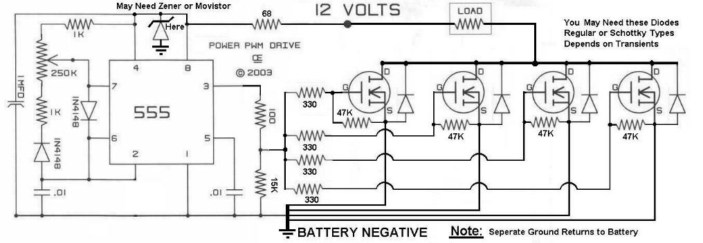
Source, the excellent Chemelec page:
A Pulse Width Modulation Control
Also Larry says:
@Ufo,Originally posted by larryross View Post
What can we do to test whether or not we have Radiant?
I think this is very important.
We need to learn to differentiate hot/cold electricity.
Comment
-
Hi @Larry,Originally posted by larryross View Post
Excellent setup, congratulations!
I hope your results very soon
Comment
-
S E T H Pdf
Seth
What you have created for others is just great. Someone mentioned a while back about doing this but none have untill now. It is also a quick summary for all of us as it does not get beat down with all the chit-chat and wrong info leading to confusion. I hope that you will keep this up to date as we are soon to be moving ahead into the nest step and having this PDF will show our true path.
Dana
PS you might run the test thru a spell checker. You have the same problem I have, head goes faster than fingers. "Today's scientist have substituted mathematics for experiments and they wander off through equation after equation and eventually build a structure which has no relation to reality."Nikola Tesla
Comment
-
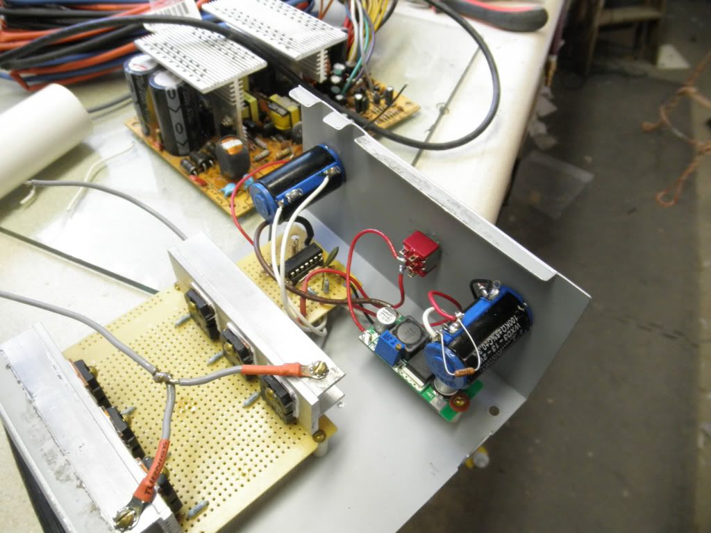
Hi all,
This is my junk yard setup in battery charger mode

Test:
Source: 2 bad bats about 19-20v
Charge bat: 12v 7A SLA
Charge time: 2:15 hours
Stars at 11.90v
Disconnect when it reached 15.82v
Much less time than in the previous charge, may be can not in good condition and do not store the correct charge.
Other test:
Source: 2 bad bats about 19-20v
Charge bat: 12v 50 amps car battery. Really around 50%=25 Amps.
Charge time: 19 hours
Stars at 11.20v
Disconnect when it reached 15.20v
Comment
-
I finally got my coil shorting going!
I had to rebuild my PWM driver as the old one has gone in smoke.
It's a 555 + LM393 + MIC4422 mosfet driver.

I've dug up my old setup with a rotor and I am driving it GAP POWER style magnets all the same pole out.
Driving coil in attraction polarity, there are magnets behind the coil in repelling mode to the rotor.
I am shorting two gen coils non stop, they're hooked up in parallel.
There is lots of radiant in shorting I'll make a short video soon.
kEhYo� THE PERSON WHO SAYS IT CANNOT BE DONE SHOULD NOT INTERRUPT THE PERSON DOING IT ! �Comment
Comment