Announcement

Collapse
No announcement yet.

My Motors got me to Tap into Radiant Energy

Collapse
X
 
  • Filter
  • Time
  • Show
Clear All
new posts

  • Originally posted by Ufopolitics View Post
    UFO
    How can I email you? I would rather not discuss my comments about your video on the forum.

    Regards
    Larry

    Comment


    • Posts

      Larry
      Click on his title name at the top of the post and select private email.
      Dana

      By the way, Thankyou for the help given in your posts.
      "Today's scientist have substituted mathematics for experiments and they wander off through equation after equation and eventually build a structure which has no relation to reality."
      Nikola Tesla

      Comment


      • Originally posted by anthonynoahan View Post
        I had gone through the post. The motors which I am using was good as I was using them from many years and doesn't came across any problem with them. Could you please produce some attachment links regarding the book that you have described. I am having the motor from the manufacturers amperis.


        partial discharge detector
        winding resistance meter
        Anthonynoahan,

        That is great you posted this. The price for the Switchgear ULD 40 in US Dollars is around $3,350.
        Switchgear ULD 40 | Amperis - Tests & measurement electrical instruments

        Found a similar one made by Amprobe at Allied Electric for $350 USD:

        Amprobe ULD-300
        Amprobe - ULD-300 - Testers - Ultrasonic - Allied Electronics

        While locating corona arcs with a camera that cost over $100,000 and rent for $18,000 for 3 months (price keeps it out of reach for most), the above test devices put detecting the corona arcs at a level more can afford.

        These devices will also help break "The Spell" as UFOPolitics puts it.

        Below is a visual of corona discharge. While they are looking at ways to eliminate it, we are looking at ways to set up the environment to direct it, manage it, and put it into positive beneficial uses.

        Eliminating Corona: Using Epsilon Midsun RTV HVIC for eliminating Corona Discharge
        Eliminating Corona: Using Epsilon Midsun RTV HVIC for eliminating Corona Discharge - YouTube

        IndianaBoys

        Comment


        • Hello Larry

          Originally posted by larryross View Post
          UFO
          How can I email you? I would rather not discuss my comments about your video on the forum.

          Regards
          Larry
          Hello Larry,

          Is there something wrong?...did you like it?...

          ufopolitics@gmail.com

          regards

          Ufopolitics
          Principles for the Development of a Complete Mind: Study the science of art. Study the art of science. Develop your senses- especially learn how to see. Realize that everything connects to everything else.― Leonardo da Vinci

          Comment


          • Understandings...

            Ok, I have been looking at this incredible work. I understand this at the basic level. The collapse of the magnetic field is creating the high voltage spike and that is being sent to be used/captured just like the Bedini SSG or window motor etc. That all makes sense to me.

            The interesting thing that I see in the video is your point about the flow and more than one coil. These streams are not running against each other(Thank you! ) But are in a flow interlaced. If I were to guess, I would say we are looking at something like a DNA strand as it winds around the center while spinning.

            I am not sure I can see how to implement this in the radio shack motors. At first I thought maybe We were going to remove the brushes etc. from one and add to the back side of the other. but that is not easily done with these motors.

            Anyway If I understand this right This is splitting the streams which I understand to be the "Secret"..... Is that fundamentally why two coils?

            One other thing that it looks like it can do is be either a generator or motor?
            This is going to require a lot of thinking but it is starting to clear some of the fog... But I can't wait to see my little motors here spinning just like what is shown. Replication is everything....


            Les

            Comment


            • Re Kogs 555 Oscillator

              [QUOTE=Ufopolitics;180157]Hello
              Originally posted by kapierenundkopieren View Post
              !!

              Yesssss!!!!! Now, That work looks AWESOME!!!

              Yes, that is perfect, I knew at least ONE of You guys will give the final touches at great detail.!!!

              That is wonderful!!

              Ufopolitics
              G'Day UFO, kapierenundkopieren,EtAl
              I am still having trouble I am sure it is the 555 Timer circuit I have ordered an Oscillator from China This one here
              eBay Australia: Buy new & used fashion, electronics & home d�r

              While I am waiting for it to come I still need to understand why this one I have tried to replicate does not work

              First of all It does seem to Oscillate, as when I Connect to the DMM set in duty cycle mode as I turn the pot from lowest about 1.4%? gradually increases to highest 99%? But when connected to the Mosfet circuit it does not turn the mosfets on.
              The volts at the output to the Gate bus on the Mosfet circuit is only about 2,5V? and this showed to be about right when I measured with the Scope
              Question
              When the 555 circuit is Oscillating and the input is 12v is not the output to the Gate bus expected to be 12v the same as the input 12v but switching at the pulse rate of the duty cycle?
              Also
              Should the frequency remain reasonably the same throughout the changing of the duty cycle?

              IN UFO's Circuit /Diagram http://www.energeticforum.com/renewa...tml#post179481
              the Wiper to the 250k pot comes from pin7 by passing the diodes before D4 (in kapierenundkopieren's it is D2) where as the wiper in kapierenundkopieren's Post here
              http://www.energeticforum.com/180140-post156.html
              comes from pin 6 before Diode His D1(which is D5 in UFO's)

              I have mine set up as per UFO's
              Please
              Which is the correct setup?
              What would stop/reduce the output volts?

              Regards

              Still

              Comment


              • You will see them...

                Originally posted by Les_K View Post
                Ok, I have been looking at this incredible work. I understand this at the basic level. The collapse of the magnetic field is creating the high voltage spike and that is being sent to be used/captured just like the Bedini SSG or window motor etc. That all makes sense to me.

                The interesting thing that I see in the video is your point about the flow and more than one coil. These streams are not running against each other(Thank you! ) But are in a flow interlaced. If I were to guess, I would say we are looking at something like a DNA strand as it winds around the center while spinning.

                I am not sure I can see how to implement this in the radio shack motors. At first I thought maybe We were going to remove the brushes etc. from one and add to the back side of the other. but that is not easily done with these motors.

                Anyway If I understand this right This is splitting the streams which I understand to be the "Secret"..... Is that fundamentally why two coils?

                One other thing that it looks like it can do is be either a generator or motor?
                This is going to require a lot of thinking but it is starting to clear some of the fog... But I can't wait to see my little motors here spinning just like what is shown. Replication is everything....


                Les
                Hello Les, Thanks and yes...you will see them...

                Regards


                Ufopolitics
                Principles for the Development of a Complete Mind: Study the science of art. Study the art of science. Develop your senses- especially learn how to see. Realize that everything connects to everything else.― Leonardo da Vinci

                Comment


                • [QUOTE=iankoglin;201290]
                  Originally posted by Ufopolitics View Post
                  Hello

                  G'Day UFO, kapierenundkopieren,EtAl
                  I am still having trouble I am sure it is the 555 Timer circuit I have ordered an Oscillator from China This one here
                  eBay Australia: Buy new & used fashion, electronics & home d�r

                  While I am waiting for it to come I still need to understand why this one I have tried to replicate does not work

                  First of all It does seem to Oscillate, as when I Connect to the DMM set in duty cycle mode as I turn the pot from lowest about 1.4%? gradually increases to highest 99%? But when connected to the Mosfet circuit it does not turn the mosfets on.
                  The volts at the output to the Gate bus on the Mosfet circuit is only about 2,5V? and this showed to be about right when I measured with the Scope
                  Question
                  When the 555 circuit is Oscillating and the input is 12v is not the output to the Gate bus expected to be 12v the same as the input 12v but switching at the pulse rate of the duty cycle?
                  Also
                  Should the frequency remain reasonably the same throughout the changing of the duty cycle?

                  IN UFO's Circuit /Diagram http://www.energeticforum.com/renewa...tml#post179481
                  the Wiper to the 250k pot comes from pin7 by passing the diodes before D4 (in kapierenundkopieren's it is D2) where as the wiper in kapierenundkopieren's Post here
                  http://www.energeticforum.com/180140-post156.html
                  comes from pin 6 before Diode His D1(which is D5 in UFO's)

                  I have mine set up as per UFO's
                  Please
                  Which is the correct setup?
                  What would stop/reduce the output volts?

                  Regards

                  Still
                  Kogs
                  This may be as stupid question but I have been watching you struggle for some time. First, if you have 2.5 volts to the gate, that part should work. Just in case, you could take a fet and do a test rig with a variable power supple to check when yours will fire. All could be low voltage and a LED/resistor setup.
                  You should also have 12 volts or so at the source pins. This is not enough to lite the cfl but good for testing. If you have 2.5v at gate and 12v at source and 0v at drain, then fets are blown. Otherwise, there is no reason for them not to work. If you are using the cfl to tell if the fet is fireing, not a good method as with all working at 12 volts only it would be hard to get cfl to go the first time without exact timing. If you think that there is no fet on time, check the gate to gound voltage and see, if you have not done so already. Just trying to help. I think that you getting the PWM will solve everything fast.
                  Dana
                  "Today's scientist have substituted mathematics for experiments and they wander off through equation after equation and eventually build a structure which has no relation to reality."
                  Nikola Tesla

                  Comment


                  • Originally posted by Les_K View Post

                    I am not sure I can see how to implement this in the radio shack motors. At first I thought maybe We were going to remove the brushes etc. from one and add to the back side of the other. but that is not easily done with these motors.

                    Anyway If I understand this right This is splitting the streams which I understand to be the "Secret"..... Is that fundamentally why two coils?

                    One other thing that it looks like it can do is be either a generator or motor?
                    This is going to require a lot of thinking but it is starting to clear some of the fog... But I can't wait to see my little motors here spinning just like what is shown. Replication is everything....


                    Les
                    G'Day Les K

                    I that the reason of 2 motors is using the coils from one motor to drive the other like he explained here http://www.energeticforum.com/renewa...tml#post183683

                    Regards

                    Comment


                    • Hello to all

                      Ok, for all of you guys to know...I have opened an specific Thread on My Asymmetric Motors-Generators here:

                      http://www.energeticforum.com/renewa...-machines.html

                      Now, go to my post number seven (7) and read what we are going to do to those two little motors... and I also have uploaded some nice pic's of the "making"...I will post a small video later on tonight..

                      Thanks and regards


                      Ufopolitics
                      Principles for the Development of a Complete Mind: Study the science of art. Study the art of science. Develop your senses- especially learn how to see. Realize that everything connects to everything else.― Leonardo da Vinci

                      Comment


                      • Sorry Ian...not that..

                        Originally posted by iankoglin View Post
                        G'Day Les K

                        I that the reason of 2 motors is using the coils from one motor to drive the other like he explained here http://www.energeticforum.com/renewa...tml#post183683

                        Regards
                        Hello Ian,

                        I am very sorry you are still struggling with your circuit!!
                        And I am really sorry...but I am having some "pressure" to upload the little Radio Shack Motor spinning... ...and have no time to go over with you...

                        Ok, You got to read my post above...go to that thread and read post number seven (7)...then you will have an idea of what I am gonna do...


                        Regards


                        Ufopolitics
                        Principles for the Development of a Complete Mind: Study the science of art. Study the art of science. Develop your senses- especially learn how to see. Realize that everything connects to everything else.― Leonardo da Vinci

                        Comment


                        • [QUOTE=prochiro;201293]
                          Originally posted by iankoglin View Post

                          Kogs
                          This may be as stupid question but I have been watching you struggle for some time. First, if you have 2.5 volts to the gate, that part should work. Just in case, you could take a fet and do a test rig with a variable power supple to check when yours will fire. All could be low voltage and a LED/resistor setup.
                          You should also have 12 volts or so at the source pins. This is not enough to lite the cfl but good for testing. If you have 2.5v at gate and 12v at source and 0v at drain, then fets are blown. Otherwise, there is no reason for them not to work. If you are using the cfl to tell if the fet is fireing, not a good method as with all working at 12 volts only it would be hard to get cfl to go the first time without exact timing. If you think that there is no fet on time, check the gate to gound voltage and see, if you have not done so already. Just trying to help. I think that you getting the PWM will solve everything fast.
                          Dana
                          G'Day Dana

                          Both my Regulator and my Mosfet circuits work Fine
                          My Regulator works fine outputs what ever I set the pot at
                          The Mosfets switch on and off 3 x 12v bulbs in series so it works fine
                          I have tested it by bypassing the Oscillator IT IS OK
                          The questions I am asking are

                          Question One
                          When the 555 circuit is Oscillating and the input is 12v is not the output to the Gate bus expected to be 12v the same as the input 12v but switching at the pulse rate of the duty cycle?
                          Also
                          Question two
                          Should the frequency remain reasonably the same throughout the changing of the duty cycle?

                          Question Three
                          IN UFO's Circuit /Diagram My Motors got me to Tap into Radiant Energy
                          the Wiper to the 250k pot comes from pin7 by passing the diodes before D4 (in kapierenundkopieren's it is D2) where as the wiper in kapierenundkopieren's Post here
                          My Motors got me to Tap into Radiant Energy
                          comes from pin 6 before Diode His D1(which is D5 in UFO's)

                          I have mine set up as per UFO's
                          Please
                          Which is the correct setup?

                          Please what could stop/reduce the output volts?

                          Regards


                          Still

                          Comment


                          • Hello Iankoglin

                            [QUOTE=iankoglin;201316]
                            Originally posted by prochiro View Post

                            G'Day Dana

                            Both my Regulator and my Mosfet circuits work Fine
                            My Regulator works fine outputs what ever I set the pot at
                            The Mosfets switch on and off 3 x 12v bulbs in series so it works fine
                            I have tested it by bypassing the Oscillator IT IS OK
                            The questions I am asking are

                            Question One
                            When the 555 circuit is Oscillating and the input is 12v is not the output to the Gate bus expected to be 12v the same as the input 12v but switching at the pulse rate of the duty cycle?
                            Also
                            Question two
                            Should the frequency remain reasonably the same throughout the changing of the duty cycle?

                            Question Three
                            IN UFO's Circuit /Diagram My Motors got me to Tap into Radiant Energy
                            the Wiper to the 250k pot comes from pin7 by passing the diodes before D4 (in kapierenundkopieren's it is D2) where as the wiper in kapierenundkopieren's Post here
                            My Motors got me to Tap into Radiant Energy
                            comes from pin 6 before Diode His D1(which is D5 in UFO's)

                            I have mine set up as per UFO's
                            Please
                            Which is the correct setup?

                            Please what could stop/reduce the output volts?

                            Regards


                            Still

                            Ian,

                            My circuit works fine...now you wrote:

                            Question One
                            When the 555 circuit is Oscillating and the input is 12v is not the output to the Gate bus expected to be 12v the same as the input 12v but switching at the pulse rate of the duty cycle?
                            May I ask you one question, a silly one, sorry, you are mentioning Gate V but you wrote "BUS"...Now, I hope you are not trying to turn on your Coil with 12V?...right?

                            It seems you have a Supply fault there...when you hook up coil it drops down...Your Coil will require -at least- 24 to 36 Volts...
                            Your Gates DO NOT need the whole 12 Volts to trigger...2 to 3 V is more than enough (like Dana said)...so there is a problem there...your oscillator is not sending right signal to FET's Gate...

                            Now you mention you turn the pot to regulate Input?...from voltage regulator ?...my circuit regulator (LM317) do not have a "pot"?...You are using an external one I guess..so, is that regulator output also hook to
                            Negative Source and Positive to Coil?

                            Could you please draw (hand draw is ok)..your whole set, including V Regulator, Coil, and the "part" of my circuit you are doing...pictures do not work...so, go over the whole thing...write it down...let's give it another try...

                            Regards


                            Ufopolitics
                            Principles for the Development of a Complete Mind: Study the science of art. Study the art of science. Develop your senses- especially learn how to see. Realize that everything connects to everything else.― Leonardo da Vinci

                            Comment


                            • QUOTE=Ufopolitics;201317]
                              Originally posted by iankoglin View Post


                              Ian,

                              My circuit works fine...now you wrote:


                              May I ask you one question, a silly one, sorry, you are mentioning Gate V but you wrote "BUS"...Now, I hope you are not trying to turn on your Coil with 12V?...right?

                              It seems you have a Supply fault there...when you hook up coil it drops down...Your Coil will require -at least- 24 to 36 Volts...
                              Your Gates DO NOT need the whole 12 Volts to trigger...2 to 3 V is more than enough (like Dana said)...so there is a problem there...your oscillator is not sending right signal to FET's Gate...

                              Now you mention you turn the pot to regulate Input?...from voltage regulator ?...my circuit regulator (LM317) do not have a "pot"?...You are using an external one I guess..so, is that regulator output also hook to
                              Negative Source and Positive to Coil?

                              Could you please draw (hand draw is ok)..your whole set, including V Regulator, Coil, and the "part" of my circuit you are doing...pictures do not work...so, go over the whole thing...write it down...let's give it another try...

                              Regards


                              Ufopolitics
                              G'Day UFO
                              I really appreciate you spending yourself for every one and especially taking the time to help me I can see you are run off your feet and please look at your my pics at your own convienience
                              I have looked at your other thread and have already purchased things to start building
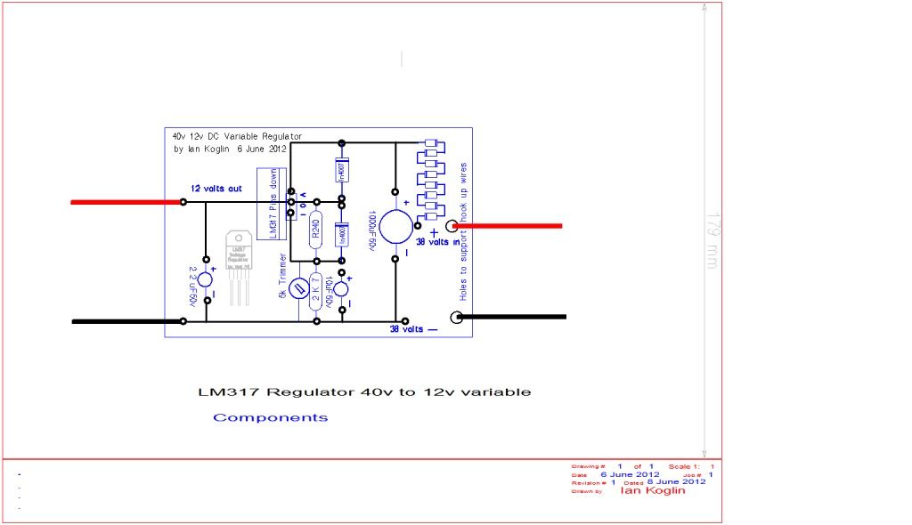
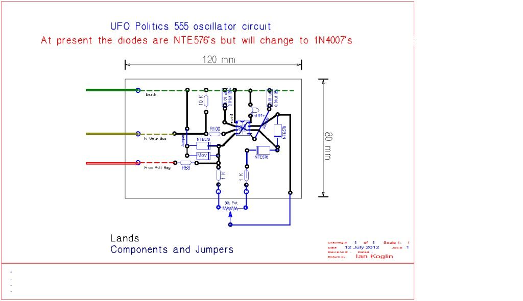
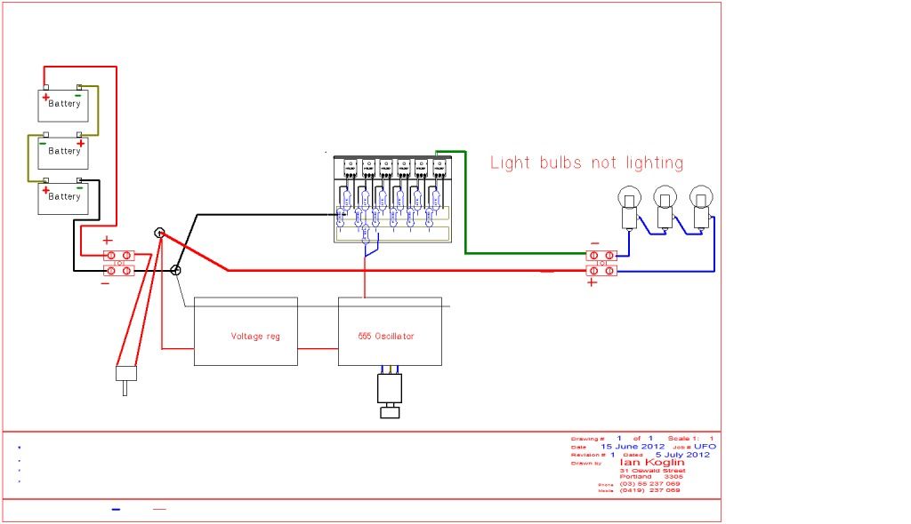
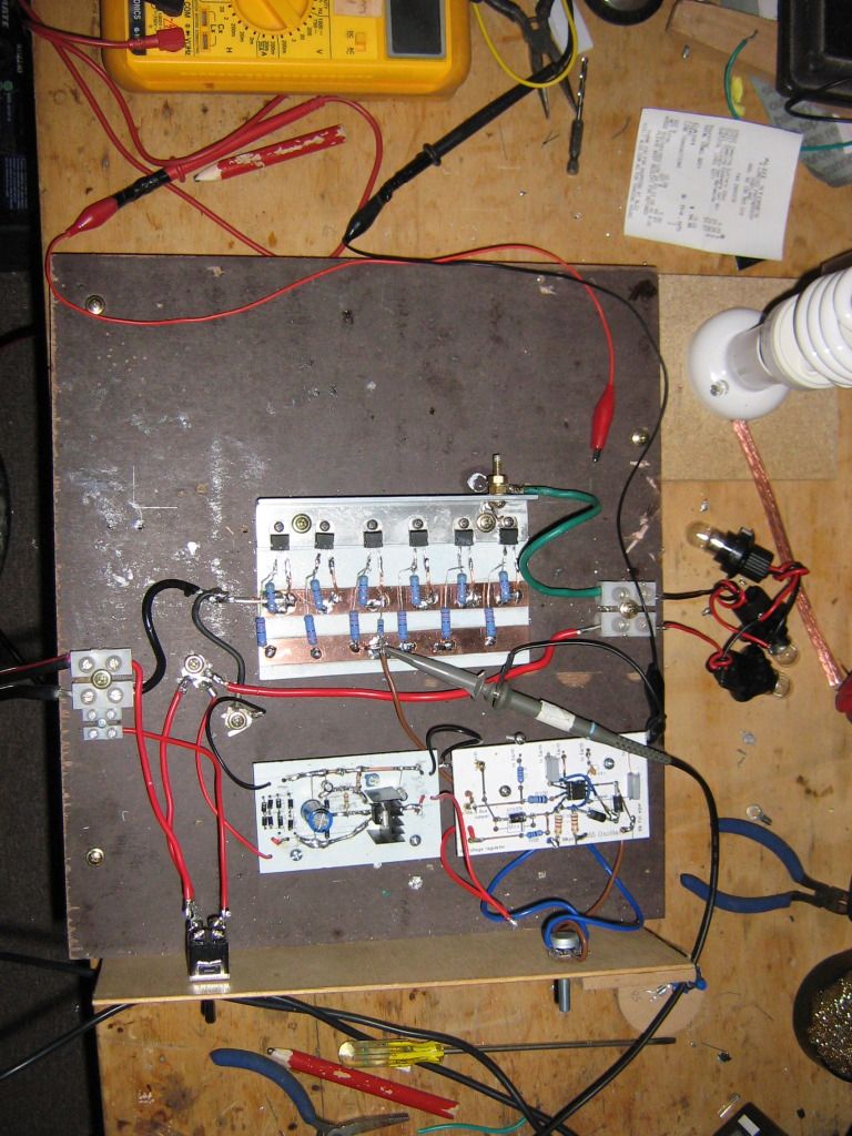
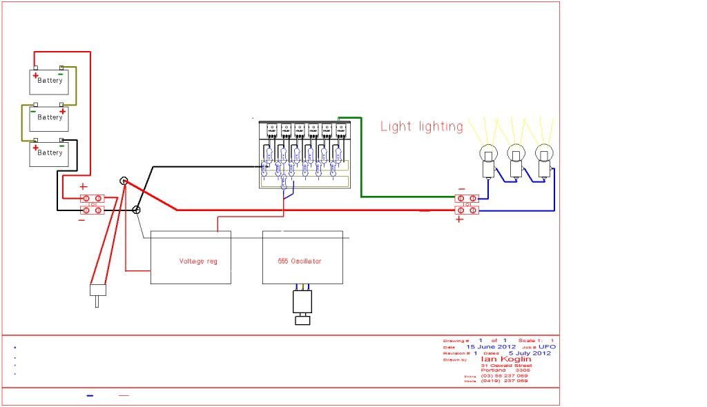
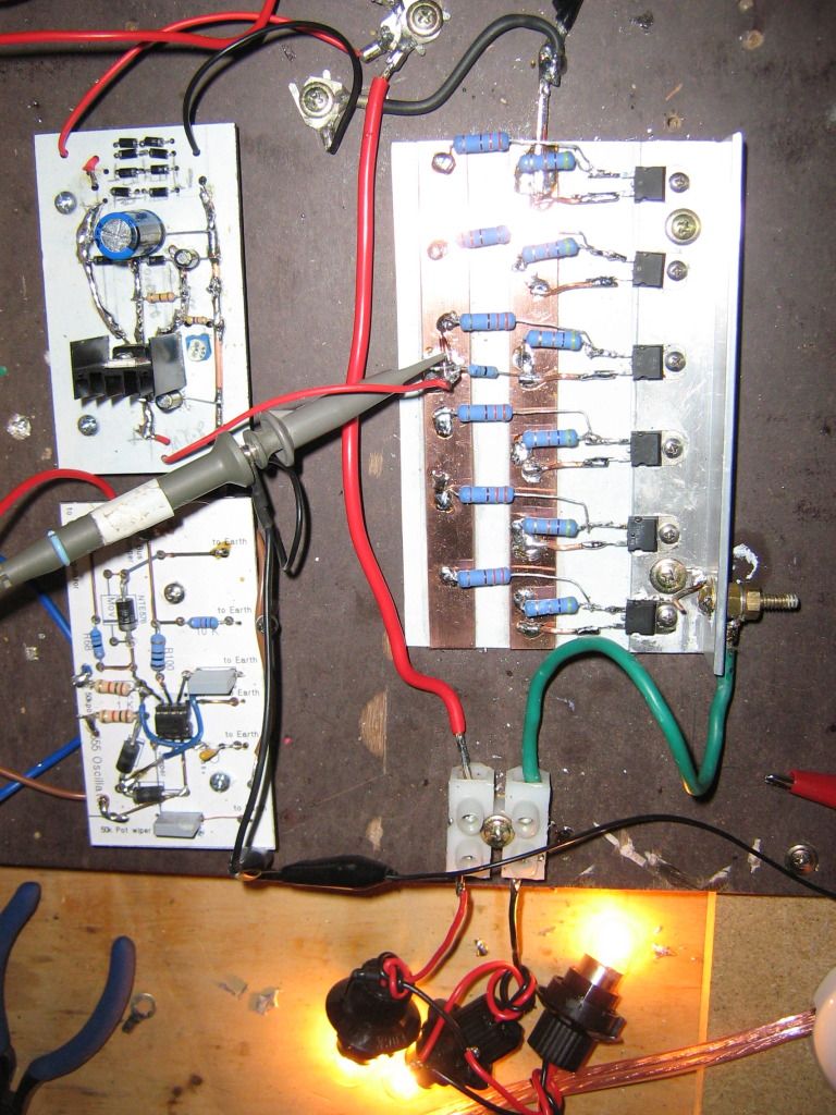
                              Here are Some drawings and pics
                              I have as yet not connected the coil as I want to get things going first

                              The regulator It surely works I have no problem its output is 12v


                              Here is the 555 Oscillator circuit
                              It as it oscillates and I turn the pot It shows a square wave that changes the Duty cycle But the volts output is only about 2 to 3 v


                              When I have the Regulator and the Oscillator connected to the circuit the bulb does not even flicker even if I move all the way thru the pot very slowly here is the circuit I have drawn here and a pic follows


                              When I disconnect the Oscillator and connect the output of the regulator the lights do come on and very bright
                              the circuit is here and followed by a pic


                              I captured a vid on my phone I do not know if it works as it Seems I cannot view my photos and vids my self but I was able to download the URL's


                              I really appreciate everything you are doing here especially being so busy and taking the time to help me

                              Kindest Regards

                              Comment


                              • Hi guys

                                For the interested here, i succesfully replicated the assymetric motor of Ufopolitics.

                                Discussion on the other thread

                                good luck at all

                                Laurent

                                Ufo assymetric motor part 1 - YouTube

                                Comment

                                Working...
                                X