Announcement

Collapse
No announcement yet.

My Motors got me to Tap into Radiant Energy

Collapse
X
 
  • Filter
  • Time
  • Show
Clear All
new posts

  • JohnS,

    If I use a PWM-OCm to generate a pulse, then run that into the NE555 FET driver (which is fed separately) to actuate the MOSFET (which has the source fed separately and power grounded), where do I put the opto? Do I need something (a 555?) between the opto and FET to square up the signal?

    At first, I will be using 12v max and one FET.

    Bob

    Originally posted by JohnStone View Post
    Hi Bob,
    confused?!?!
    I referred to your driver board with an opto for each FET. There you can add any pulse generator. Depending on output voltage you calculate the pullup resistors for the opto input.
    BTW: The opto output section needs separated supply (10V..20V) and GND based on the FET source legs. It is not the PSU of your generator. How will you perform that?

    Comment


    • JohnS,

      Yes, I see the confusion now. I didn't know just what the FOD3180 was when I posted before. I've looked it up now and won't use it initially because it only goes up to 250kHz, and I want to try to get at least double that (though 250kHz should work if I can keep the duty cycle below 25%.

      Thanks,

      Bob


      Originally posted by bobfrench@fastmail.fm View Post
      Yes, Johns,

      That's exactly what I need to hear. Thank you so much.

      So, should I add an opto-coupler after the PM, then the NE555 FET Driver, then sect. F (using a FOD3180) ?

      Thanks for all your help,

      Bob

      Comment


      • Hi Bob,
        The FOD was born in order to drive FETs at gate with up to 2A - no need for additional help by 555 (max 200mA).

        The main task is to drive as much current into the gate cap as possible. No slow garden hose (555) but the hose from fire fighters (FOd..). This hose will pump your gate cap up within 55 ...75 ns. That would be good for about 10MHz. Confused?

        Please do not mix frequency with steep edges. If the FOD is capable for 250 KHz it is valid for the opto transmiter/receiver. This does not mean the driver itself is lazy and slow. The edges at output are way faster (see above). But because of the opto it can not change its state faster than 250KHz.

        We do not need such high frequencies for pulsing but steep edges (Instant water from fire hose!).
        Experts spend hours a day in order to question their doing while others stopped thinking feeling they were professionals.

        Comment


        • pwm schematic

          Hi All,

          Been reading and learning.

          I thank God for UFO's willingness to help all and not look for money.

          PL will no doubt try to cash in some how with a book and or dvd's with UFO's material.

          Can't seem to locate a PWM schematic on the thread that is debugged and will work with UFO's coil setup.

          Was there a point in time on this thread that a good functional schematic was established that a medium skilled tech could build?
          I know that there are several posted but someone seems to have a need to redo what is posted.

          Your direction would be much appreciated.

          Feel capable of doing ok with reliable schematic.

          Very greatful that you all are here. We are on the winning team!

          bro d

          Comment


          • To Donald Haas

            Originally posted by Ufopolitics View Post
            Hello to ALL,

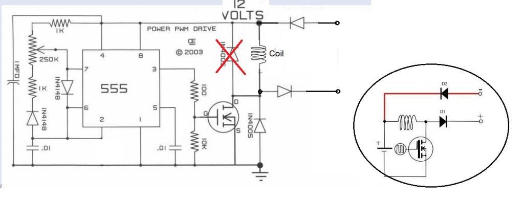
            I am presenting here the simplest PWM (Pulse Wave Modulator) and Motor Controller that you could build, it is based on the very cheap 555 Timer...and it could work "Safely"with up to 12 Volts...without the need of a Voltage Regulator.

            [IMG][/IMG]

            This is the circuit I have been using all along in My very First Thread, I just added an LM317 Voltage regulator that is posted in my other Thread, it consist of the Transistor LM317, a couple of Electrolytic Caps and a couple of resistors...and I did it in order to apply a Higher Input that ranges from 24V to 36 Volts...But the basic circuit is this one here.
            Timer works in the "Astable" Mode...rendering a very clean Square Wave...
            You will need this as a Controller to run from the very small Motors to the Bigger ones...so it is very practical...

            Also it will allow by just adding "Two Components" a Non Polarized Cap and a Diode...to make a SEPIC System that will control Input and Output from Machine Gates.

            I got this Circuit from: PROJECTS

            On:A Pulse Width Modulation Control

            I highly recommend this site for other great electronic free circuits as Switching Power Supplies and others...as Gary also sells parts there and the assembled circuits (for those that rather order them)...He is a very nice guy.

            I am not saying the other circuits are not good, on the contrary, the LM393 is a great circuit (Mad Scientist)...as it allows regulations of Duty Cycle and Frequencies...As also the great Modular Circuit designed by My Friend John Stone...However, they could become pretty complicated and all we are trying here is to Keep It as Simple as Possible...(note I did not write KISS... )

            To all the Members that have replicated my work:...I highly recommend to build this simple circuit...as it is the ONLY way you could see How My Machines Output True Radiant Energy Purple Plasma Sphere of Light...manifested at very low pulses...in the Electrodes of a 120 V Neon Bulb...


            ...and I know you will love HER...as SHE is the reason why we are getting all this "Phenomena" that many can not explain to be possible...then you all will understand better everything displayed here...as How I found HER originally...

            I believe it is a very lovely light you could not miss to see...


            Regards to all


            Ufopolitics
            Hello Donald Haas and

            I am quoting myself on an old post...here is the simple circuit AI have been using (so far)...even though Sir John Stone does not like it much... ...kidding John!


            Regards to all


            Ufopolitics
            Principles for the Development of a Complete Mind: Study the science of art. Study the art of science. Develop your senses- especially learn how to see. Realize that everything connects to everything else.― Leonardo da Vinci

            Comment


            • Mr UFO

              Mr UFO,
              You are the best!


              Originally posted by Ufopolitics View Post
              Hello Donald Haas and

              I am quoting myself on an old post...here is the simple circuit AI have been using (so far)...even though Sir John Stone does not like it much... ...kidding John!


              Regards to all


              Ufopolitics

              Comment


              • Hi Donald,
                I agree with UFO's reccomendation. It is essential to get it going first while keeping it simple. There are many ways to start and chances to optimize. And you will proceed the direction you can handle.
                Please ask further questions if you need help.
                rgds John
                Experts spend hours a day in order to question their doing while others stopped thinking feeling they were professionals.

                Comment


                • @ALL: I am so sorry that many of you are plain newbies in electric matters and it is very difficult for you to understand what these bloody circuits really do. I decided to give you a primer and I hope it helps a bit. I deduce most of my notions from this thinking model below.

                  You can understand electricity if you imagine flowing water.
                  • Voltage is the pressure in the water tube.
                  • If you open the tap (switch) you will get water flow (current).
                  • If you open it fully (like a switch) you get max. water flow but no pressure left -> battery in short ciruit mode. Any battery owns an internal resistance (flow resistance in the tubes) and this gives the max current at short cicuit.
                  • If you connect a long garden hose to the tap and open it (tap = switch) then you will get less water flow through the hose because of its flow resistance. Your hose is a resistor. If you make the hose longer you will get more resistance and less water flow (current). If you connect two hoses in parallel you will get less resistance and more water flow.
                  • If you connect a bottle (bottom up) to the hose you have a capacitor. Water flows into it (charging) and the air pressure increases up to the pressure of your water supply (max voltage, charged). If you disconnect the hose from the bottle it will discharge instantlly like a charged cap being short circuited. If you connect a long hose (resistor) to it then the discharging cycle will take more time. If you charge the bottle, close it and disconnect the hose you have a charged cap sitting there being disconnected.
                  • If you try to imagine an inductor it is a bit complicated. Inductors along current is a dynamic thing and same with water. You know the effect: If you close a water tap very fast you get a beat in the supplying tubes. Why? Well, we know the water has mass and while tapping water it was accellerated. If you close the tap quickly the water will increase the pressure at the end considerably - it is hammering - because of deceleration. Same if you charge a coil with current and open the circuit instantly - you will get very high pressure (sorry voltage). Now we simulated here the inductive property of long battery leads. The inductivity of a battery is very low but if you have long leads it will increase (corresponding to the length of your water supply tubes).
                  • In order to imagine an inductor at load side imagine a hydrolic pump. It can be driven by oil pressure but if turnd at the shaft it will be a pump. Now add a flywheel (mass = Henry) to the shaft and connect your hose to it. The water flow will slowly increase because you pump energy into the flywheel being accellerated. The more rpm the more amps (sorry water flow). If you stop the water flow the flywheel will start pumping and it will produce considerable pressure at output though the water tap is closed.
                  • If you install a one way walve at the pump output (diode) you can store the pressure in a bottle. You have a switched mode step up PSU.
                  • Any battery has inductance (leads), capacitance (plates) and resistance (electrolyt). For very short time you can get excessive amps out of the inherent capacitance but the current will be somewhat delayed because of the inductance of the leads. Later on you have more resistance because you discharge the cap a bit and the electrolyt needs to produce further current flow.
                  • Imageine the FET to be a valve and you open and close it by a piston. But unfortunately you have a inhernet bottle build in. You need to pump up the bottle before the piston is ready for moving. So you need much water for short time in order to pump up the bottle within short time. High currrent (water flow) required. Your FET driver is a valve and it needs to have huge cross section in order to enable the throughput required for fast switching. Unfortunately the FET driver is being connected to PSU leads (long hoses) and will not be able to propagate more volume of water within short time than it gets form thelong supply hoses (resistance along instant moving of mass = inductance). But we are smart and have installed bottles (caps of different properties) at power leads before the valve in order to have a storage device. If we open the driving valve its bottle will discharge rapidly and pump up the other bottle sitting inside the gate of our FET. And then the FET valve will move.
                  • Unfortunately the devices above are connected by hoses as well and the moving water along the bottles tend to start oscillations. They originate from the botles under pressure (caps) and the mass of water (inductance) Therefore we introduce a resistance 10ohm (smaller or longer hose) between driver and FET in order to get the water exchange from driver to gate smooth without oscillations (damping oscillations).
                  • I imagine radiant as additional syringe you can activate by hammering your hoses and especially your flywheels mentioned above. This will inject a jet of water directly into your hoses being hammerd.
                  • This is all you need in order to learn watching with your mind what circuits do. Any conductor is a resistance, cap, inductor at same time. If you grow up the resistance you have a resistor but at same time it is a bonsai inductance - it is a bush if wound by wire. If many windings applied it is a tree and you account it as inductor with some minor resitance. Sometimes the tiny values of some properties like inductance can be neglected sometimes not. That is the fine art teaching you to know when to account for what. You can imagine any electric device or circuit this way and after some mind training you will easily watch the electricity acting lagging any meter.
                    Neverthelss this is a restricted thinking model and will not explain all electric or radiant factors.
                    Now you have your toys available: bottles, hoses, pumps, flywheel.... Tinker with them and imagine water volume flowing, imagine its inertia and operate valves.
                  Last edited by JohnStone; 12-06-2012, 11:40 AM.
                  Experts spend hours a day in order to question their doing while others stopped thinking feeling they were professionals.

                  Comment


                  • Hello UFO,

                    I have edited the circuit diagram to be consistent with the other diagrams in the first few posts. Just trying to avoid confusion with the other members. I hope you don't mind.

                    Lester

                    Comment


                    • Thanks!

                      Originally posted by Lester444 View Post
                      Hello UFO,

                      I have edited the circuit diagram to be consistent with the other diagrams in the first few posts. Just trying to avoid confusion with the other members. I hope you don't mind.

                      Lester

                      Oh Thank You absolutely Lester 444!!

                      I completely forgot about the "Flywheel" diode there!!...the thing is that circuit is exactly the same diagram from Gary's site...

                      The other Diode below the FET (between Drain-Source) is to replace the intrinsic diode FET's come with...or better said...to assist it.

                      Great idea to post my original simple "extra diode and piece of wire"...that brought so much controversy here...

                      Thanks again Lester444!!

                      Regards


                      Ufopolitics
                      Principles for the Development of a Complete Mind: Study the science of art. Study the art of science. Develop your senses- especially learn how to see. Realize that everything connects to everything else.― Leonardo da Vinci

                      Comment


                      • Will proceed

                        Thanks UFO, John Stone and Lester444,

                        I'll do the last posted version of UFO's recommend PWM.

                        I read about the troubles that Netica and Kogs had and see the payoff because of the "don't quit spirit."

                        Thank you all for being willing and able to help.

                        bro d

                        Comment


                        • Fod

                          Johns,

                          OK, good. So if I run the FOD, etc., at 250kHz, will it allow a duty cycle of 25% or less? Then I could have a 1 micro second, or less, ON time. What size gate cap would you suggest in this particular situation?

                          I may get this project tried yet. Thanks for your help.

                          Bob


                          Originally posted by JohnStone View Post
                          Hi Bob,
                          The FOD was born in order to drive FETs at gate with up to 2A - no need for additional help by 555 (max 200mA).

                          The main task is to drive as much current into the gate cap as possible. No slow garden hose (555) but the hose from fire fighters (FOd..). This hose will pump your gate cap up within 55 ...75 ns. That would be good for about 10MHz. Confused?

                          Please do not mix frequency with steep edges. If the FOD is capable for 250 KHz it is valid for the opto transmiter/receiver. This does not mean the driver itself is lazy and slow. The edges at output are way faster (see above). But because of the opto it can not change its state faster than 250KHz.

                          We do not need such high frequencies for pulsing but steep edges (Instant water from fire hose!).

                          Comment


                          • Output diodes and mosfets

                            Edited circuit shows output diodes that are not numbered or valued.

                            UFO calls them fast switchers, 400v and up.
                            Need a part number or info if someone could help.

                            these mosfets look ok?
                            Mouser #: 511-STP11NM60ND
                            100% avalanche tested
                            RDS .45
                            600v, 10a

                            Many thanks,

                            bro d

                            Comment


                            • Found diodes at mouser

                              NTE576

                              bro d

                              Comment


                              • Hello Donald

                                Originally posted by Donald Haas View Post
                                Edited circuit shows output diodes that are not numbered or valued.

                                UFO calls them fast switchers, 400v and up.
                                Need a part number or info if someone could help.

                                these mosfets look ok?
                                Mouser #: 511-STP11NM60ND
                                100% avalanche tested
                                RDS .45
                                600v, 10a

                                Many thanks,

                                bro d
                                Hello Donald Haas,

                                That FET looks ok, is fast (RDS On 0.45)...but make sure the 10A are linear rating, as "Pulsed Drain Current" (PDC) they should mark higher...

                                I use the NTE 2397 and note on the linked pdf that its PDC is 40 A
                                The Ultrafast Rectifiers I use are UF505/NTE576
                                Those are the best so far...

                                Regards


                                Ufopolitics
                                Principles for the Development of a Complete Mind: Study the science of art. Study the art of science. Develop your senses- especially learn how to see. Realize that everything connects to everything else.― Leonardo da Vinci

                                Comment

                                Working...
                                X