 Tweet
Tweet
[QUOTE=bobfrench@fastmail.fm;217543] So if I run the FOD, etc., at 250kHz, will it allow a duty cycle of 25% or less? Then I could have a 1 micro second, or less, ON time. What size gate cap would you suggest in this particular situation?
I may get this project tried yet. Thanks for your help.
Bob[/QUOTE
Offitial facts:
The opto is the slowest link in the chain and the FET driver behind will not switch more pulses per second than 250KHz. But those pulses have very steep slopes and those are a value in themselves for OU.
Inofficial facts:
But please note: The manufacturer garantees that the devices will perform at 250KHz. That is the max. they guerantee. But you as applicator stay on the other side and there you are told that they will exeed this limit for sure. Manufacturers can't avoid it as the technologies applied enable faster components than at initial launch some years ago. So be of good mood and check what FODs can do for you.
Question: Why do you intend to switch so fast. The motor windings will not account for it. They will ignore it like your ears the ultrasound of bats.
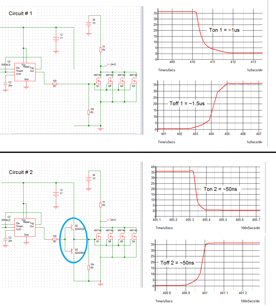
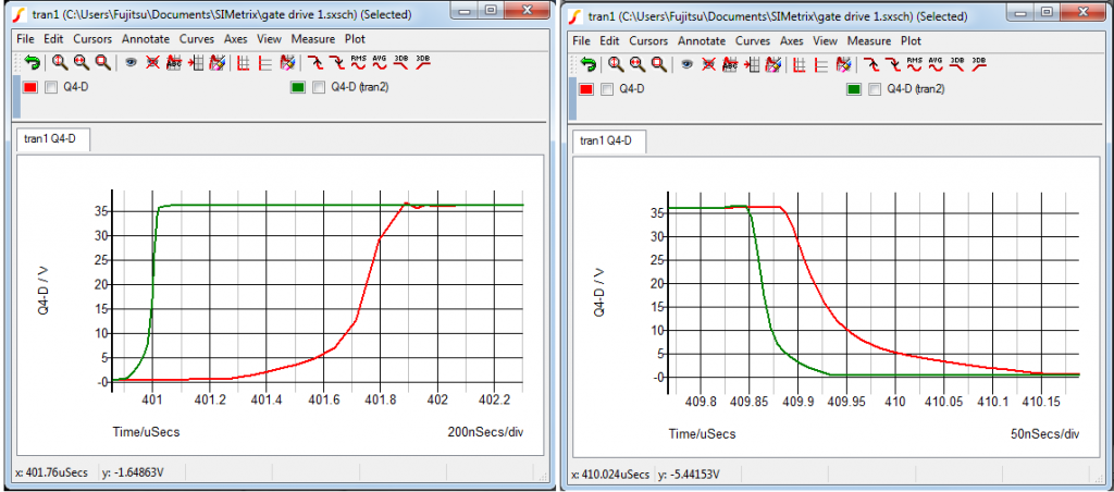
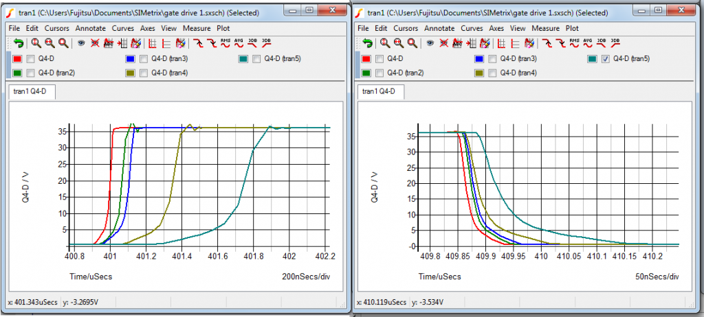
The gate cap is inherent and can't be avoided - it is a side effect of FET technology. You can get rid of a tick but not of the gate cap. It is definitley not helpful or intended but present. You must live with it and try to make it harmelss for your application. You do this i.e. by applying a good driver in order to charge/discharge it as quick as possible. Regard it like slack in mechanic device.
I may get this project tried yet. Thanks for your help.
Bob[/QUOTE
Offitial facts:
The opto is the slowest link in the chain and the FET driver behind will not switch more pulses per second than 250KHz. But those pulses have very steep slopes and those are a value in themselves for OU.
Inofficial facts:
But please note: The manufacturer garantees that the devices will perform at 250KHz. That is the max. they guerantee. But you as applicator stay on the other side and there you are told that they will exeed this limit for sure. Manufacturers can't avoid it as the technologies applied enable faster components than at initial launch some years ago. So be of good mood and check what FODs can do for you.
Question: Why do you intend to switch so fast. The motor windings will not account for it. They will ignore it like your ears the ultrasound of bats.
The gate cap is inherent and can't be avoided - it is a side effect of FET technology. You can get rid of a tick but not of the gate cap. It is definitley not helpful or intended but present. You must live with it and try to make it harmelss for your application. You do this i.e. by applying a good driver in order to charge/discharge it as quick as possible. Regard it like slack in mechanic device.


Comment