Announcement

Collapse
No announcement yet.

My Motors got me to Tap into Radiant Energy

Collapse
X
 
  • Filter
  • Time
  • Show
Clear All
new posts

  • Moster Driver

    Originally posted by JohnStone View Post
    Hi Machine!
    Welcome back in workshop!
    My driver is a well tuned entity and shall not modified and mised deliberately. But do not worry I support you . I do not know what your goal is:
    A. Original Monster driver but replace SFH617 with FOD3180. This does not really make sense! But can be done - on request!

    B. Enhancement of your current setup. I tinkerd for modifying the original monster dirver V5.1.
    WARNING:
    This version of driver does not have those superiour properties of the original circuit. It shall be used along FETs with gate capacity lower than 1.5nF. Else check frequently for heat.
    For moderate use with smaller motors this circuit might be used. There is no power on delay and signals are not restored.

    FOD3180 is FET driver with opto input - isolated! You are not suggested to feed the power from Arduino board as you want to have galvanic separation. But first facts first!

    1. Your Arduino can source and sink those 10 mA you need to input. As the input LED at opto eats up 1.5V you consider 3.5V / 10mA and compute 350Ohm - take 330Ohm an it will be OK. Else use 1K for 12V generator.

    2. Your Arduino sources very clear signals thus you do not need any conditioning. Please use two twisted wires from Arduino to FOD3180 (port / GND) in order to prevent interference from your Setup.

    3. Do not make any other connection from your Arduino!

    4. Provide a separated PSU for FOD3180. I suggest you look in your scrap box in order to extract an old socket charger delivering a voltage between 15... 18V - open output! It will need to supply some mA only - 100mA will be great.

    5. Connect a 100µF and 100nF in parallel directly where you solder the leads of charger - for blocking any interference.

    6. The output section of FOD3180 is very same like that micrel driver on my board (but 2A output instead 12A). You may continue like my PCB suggests.

    7. If the descripion above is your desire: see your personal version


    circuit
    assembly
    wiring bottom
    ~o0o~

    Regarding avalanche: It can be used safely if we add overcurrent protection. I did not touch this item up to now in order to not deviate.
    ~o0o~

    JohnS


    John Stone,

    I have been out for the last week and have just started to catch back up
    on some of the things being discussed.

    It looks like this circuit has changed some, and I want to finish up on the
    Eagle board layout.

    Is this new circuit what I sould use now, or has there been more changes in
    the last week?

    Mark

    Comment


    • Originally posted by iankoglin View Post
      G'Day John
      Here is my Updated Drawing

      https://www.dropbox.com/s/a7pm9a4fn0...%20Ver2b.T3001

      Please could you explain where
      1. Two capacitors 100nF ceramic missing at pin 13 and 14 to GND .

      2. Add an additional cap of 10µF between power feed and GND does it fit across pos and neg after the diodes ?.

      3. I want to use a voltage regulator so please what is the max voltage to input to this circiut ?.

      4. Are the In400x diodes correct?

      I really appreciate your input
      Kindest regards


      Always asking Questions
      Hi,
      I dared to modify your circuit in order to prevent misunderstanding. Here is my mod.

      You performed quite well. Some minor errors from a beginner - you will master it.

      Did you observe these controls for selecting:

      The center one selects if you mark a whole symbol or its components like value and reference. Once picked you can rotate them by right mouse button ans reposition them.

      Regarding voltge regulator: The resistors before opto LEDs is calculated for 12V. If you supply 12V all is ok. You can go up to 30V if you like but need to recalculate the resitors. Be sure the caps are rated for your supply!
      JohnS
      Experts spend hours a day in order to question their doing while others stopped thinking feeling they were professionals.

      Comment


      • Originally posted by Rl2003 View Post
        John Stone,

        I have been out for the last week and have just started to catch back up
        on some of the things being discussed.

        It looks like this circuit has changed some, and I want to finish up on the
        Eagle board layout.

        Is this new circuit what I sould use now, or has there been more changes in
        the last week?

        Mark
        Hi Mark,
        no no no. Sorry this is no recent circuit. It was a misunderstanding with Machine. This circuit is a short cut if someone who wants to drive low amps and does not need to drive them fast.
        The recent circuit is still V5.1. Sorry, I have not finished the current manual for this circuit.
        JohnS
        Experts spend hours a day in order to question their doing while others stopped thinking feeling they were professionals.

        Comment


        • Originally posted by Cornboy 555 View Post
          Good one Machine, look forward to you pulsing that beast with a monster.

          @ Jonh Stone, i am preparing to build pulsing units for MAG3, i will use seperate 12v SLA to power drivers and 74HC so will use7805 for 74HC and direct power from battery with resistor, not 7812? am i looking at this correctly?

          If this is correct i notice max input current for micrel is 50MA, what current would you recomend for powerfull but long opperation, and what wattage and ohm's value for resistor?

          Displaying my very limited electronics knowledge here, these are basic questions, i know.

          Thanks in advance Cornboy.
          Hi Cornboy,
          if we agree to not use any shortcuts being dangerous for the setup causing in best case malfunction in experimenting stadium:

          1. Power Arduino PWM from a separate PSU or PC directly.
          2. Separate output signal bay optos.
          3. Power whole driver from a separate PSU . Battery without 12V regulator will be ok but you need to get it charged and need to prevent interference by electromagentic fields. You need to connect the battery with short wires and + / GND running in prallel and twisted.
          The circuit does not take much current -100mA will be max. imaginable. Any 12..15V Socket charger will do the same job!
          4. MAG3 drive current is a completely separated PSU. The only connection to your driver PSU is via GND ON DRIVER BOARD itself!!!!
          JohnS
          Experts spend hours a day in order to question their doing while others stopped thinking feeling they were professionals.

          Comment


          • 12v ?

            Originally posted by JohnStone View Post
            Hi Cornboy,
            if we agree to not use any shortcuts being dangerous for the setup causing in best case malfunction in experimenting stadium:

            1. Power Arduino PWM from a separate PSU or PC directly.
            2. Separate output signal bay optos.
            3. Power whole driver from a separate PSU . Battery without 12V regulator will be ok but you need to get it charged and need to prevent interference by electromagentic fields. You need to connect the battery with short wires and + / GND running in prallel and twisted.
            The circuit does not take much current -100mA will be max. imaginable. Any 12..15V Socket charger will do the same job!
            4. MAG3 drive current is a completely separated PSU. The only connection to your driver PSU is via GND ON DRIVER BOARD itself!!!!
            JohnS
            Hey John, with all my thinking, i am thinking portable right from the start, even programing arduino.

            It would be great to remove micro from driver unit to take to desk top and re program and replace to drive unit.

            I still strugle with 12v 7812. i understand this is to supply VCC on micrel? specs are min 14v supply to IN on 7812 and yet AUX-PWR K8 is 12v+.

            Am i looking at this wrong?

            Regards Cornboy.

            Comment


            • Curcuit

              Originally posted by JohnStone View Post
              Hi Mark,
              no no no. Sorry this is no recent circuit. It was a misunderstanding with Machine. This circuit is a short cut if someone who wants to drive low amps and does not need to drive them fast.
              The recent circuit is still V5.1. Sorry, I have not finished the current manual for this circuit.
              JohnS


              Ok John I got it, I am glad you cleared that up.

              Mark

              Comment


              • Originally posted by Cornboy 555 View Post
                Hey John, with all my thinking, i am thinking portable right from the start, even programing arduino.

                It would be great to remove micro from driver unit to take to desk top and re program and replace to drive unit.

                I still strugle with 12v 7812. i understand this is to supply VCC on micrel? specs are min 14v supply to IN on 7812 and yet AUX-PWR K8 is 12v+.

                Am i looking at this wrong?

                Regards Cornboy.
                Hi Conboy,
                you are fully right with your question. In this area everybody will enter in his own solution.

                Let's look at detail:
                • The FETs accept up to 20V max. at their gates.
                • They are switched on fully to their spec at 10V.
                • It is advantageous to have high voltage (let's say 18V) in order to transit fast through the real switching zone at switch on time.
                • The next standard regulator is 15V needing 17V minimum at input.
                • A 12V regulator needs 14V at input indeed. I choose this voltge because it is the minimum acceptable.


                Of course you can use i.e. a motor cycle battery being fully charged (i.e. 13.5V) (omitting 12V or 15V regulator) and it will do fine.
                For research phase it is essential to not supply electronics from power train in order to prevent any disturbance (i.e. radiant entering).
                So for research we have 3 supplies:
                - 5V for arduino
                - 12V.....20V for driver
                - xxV for power train

                Any abbreviaton can be done but on own risc. i.e. you can omit opto and supply 5V to arduino from driver 5V directly: BUT - then you are warned to connect your PC to this assembly while switching FETs.

                Please understand that general advice can be supplied on safe area only.

                One safe setup would be to use your motor cycle battery directly omitting regulator 12V and adding a small DC/DC convertor inorder to supply Arduino. Then you are safe again. Might be confusing but sorry tere is a wealth of possibilities.
                If you desire to supply all electronics from a separate battery I will elaborate this to the community on request.

                Later on we will supply the electronics from power train by DC/DC PSU of course.
                JohnS
                Experts spend hours a day in order to question their doing while others stopped thinking feeling they were professionals.

                Comment


                • Kogs gradually Learning

                  Originally posted by JohnStone View Post
                  Hi,
                  I dared to modify your circuit in order to prevent misunderstanding. Here is my mod.

                  You performed quite well. Some minor errors from a beginner - you will master it.

                  Did you observe these controls for selecting:

                  The center one selects if you mark a whole symbol or its components like value and reference. Once picked you can rotate them by right mouse button ans reposition them.

                  Regarding voltge regulator: The resistors before opto LEDs is calculated for 12V. If you supply 12V all is ok. You can go up to 30V if you like but need to recalculate the resitors. Be sure the caps are rated for your supply!
                  JohnS
                  G'Day John
                  You are a real Gem I havent figured out what sort yet probably a red opal

                  Thanks for the mods I thank you that you did not connect C5 that you had in the schematic but not included on the PCB I spent a lot of time when drawing up this circuit trying to jumper the wires that crossed and as you realised I did this by making a 2pin jumper that you by passed. I was determined today to include the C5 and in doing so I had to figure how to add the jumper on top of the PCB
                  As you can see I did it

                  Here is the amended drawing

                  https://www.dropbox.com/s/ikbstff6nz...0%282%29.T3001

                  I did see those controls and have to fiddle with them to see exactly what they do.
                  and thanks again my friend
                  Kindest regards Kogs


                  with a thick head but slowly learning

                  Comment


                  • Originally posted by iankoglin View Post
                    G'Day John
                    You are a real Gem I havent figured out what sort yet probably a red opal

                    Thanks for the mods I thank you that you did not connect C5 that you had in the schematic but not included on the PCB I spent a lot of time when drawing up this circuit trying to jumper the wires that crossed and as you realised I did this by making a 2pin jumper that you by passed. I was determined today to include the C5 and in doing so I had to figure how to add the jumper on top of the PCB
                    As you can see I did it

                    Here is the amended drawing

                    https://www.dropbox.com/s/ikbstff6nz...0%282%29.T3001

                    I did see those controls and have to fiddle with them to see exactly what they do.
                    and thanks again my friend
                    Kindest regards Kogs


                    with a thick head but slowly learning
                    Hi,
                    well all is fine. And you found how to add those jumpers! Great.
                    One hint: I doubt you intentonally added unplorized film caps 47µ. Try to replace them by electrolitic ones 30....50V depending on your PSU planned.
                    Howto:
                    selct both caps 47µ (with CTRL key pressed) in schematic
                    Go to menu "components" -> "replace components" -> selcet corresponding electriolitic cap in the components view -> replace
                    Then adjust them in PCB view.
                    John
                    Experts spend hours a day in order to question their doing while others stopped thinking feeling they were professionals.

                    Comment


                    • More Questions Sorry.

                      Originally posted by JohnStone View Post
                      Hi Conboy,
                      you are fully right with your question. In this area everybody will enter in his own solution.

                      Let's look at detail:
                      • The FETs accept up to 20V max. at their gates.
                      • They are switched on fully to their spec at 10V.
                      • It is advantageous to have high voltage (let's say 18V) in order to transit fast through the real switching zone at switch on time.
                      • The next standard regulator is 15V needing 17V minimum at input.
                      • A 12V regulator needs 14V at input indeed. I choose this voltge because it is the minimum acceptable.


                      Of course you can use i.e. a motor cycle battery being fully charged (i.e. 13.5V) (omitting 12V or 15V regulator) and it will do fine.
                      For research phase it is essential to not supply electronics from power train in order to prevent any disturbance (i.e. radiant entering).
                      So for research we have 3 supplies:
                      - 5V for arduino
                      - 12V.....20V for driver
                      - xxV for power train

                      Any abbreviaton can be done but on own risc. i.e. you can omit opto and supply 5V to arduino from driver 5V directly: BUT - then you are warned to connect your PC to this assembly while switching FETs.

                      Please understand that general advice can be supplied on safe area only.

                      One safe setup would be to use your motor cycle battery directly omitting regulator 12V and adding a small DC/DC convertor inorder to supply Arduino. Then you are safe again. Might be confusing but sorry tere is a wealth of possibilities.
                      If you desire to supply all electronics from a separate battery I will elaborate this to the community on request.

                      Later on we will supply the electronics from power train by DC/DC PSU of course.
                      JohnS


                      Thanks John, so if you supply the 12v regulator with a 12v 7a sla battery will it be enough to switch Fets properly?

                      For me it would be great to keep it simple as possible and to supply all driving electronics with a 12v battery completely seperate from motor power supply which will be a bank of 100ah deep cycle batteries, with 3 farrad audio caps across them, for inrush.

                      There will be so many wires every where with 6 driver units, the more simple the better.

                      If you could show the best method to do that it would be great, sorry if this confuses anyone.
                      Please don't spend a heap of time on this John , No hurry, i am just preparing in advance.

                      Just a small schematic showing hookup and resister values etc would be plenty, i can build anything from schematic.
                      I know absolutly nothing about Arduino, can it be altered while motor is running, or do you stop - reset and then Go?.

                      If it can be programed while electronics are running, i will need to buy another PC.

                      Using DC/DC converter for Arduino sounds like a good saftey measure John, thanks.

                      Warm Regards Friend

                      Cornboy.
                      Last edited by Cornboy 555; 02-19-2013, 12:16 AM.

                      Comment


                      • See inserts in your text:
                        Originally posted by Cornboy 555 View Post
                        Thanks John, so if you supply the 12v regulator with a 12v 7a sla battery will it be enough to switch Fets properly?
                        NO: supply directly while omitting 12V regualtor.

                        For me it would be great to keep it simple as possible and to supply all driving electronics with a 12v battery completely seperate from motor power supply which will be a bank of 100ah deep cycle batteries, with 3 farrad audio caps across them, for inrush.
                        Got it - might be a common desire for others as well

                        There will be so many wires every where with 6 driver units, the more simple the better.
                        You are adviced to screw drivers and Arduino on a board and wire them there in order to pertain overview.

                        If you could show the best method to do that it would be great, sorry if this confuses anyone.
                        Please don't spend a heap of time on this John , No hurry, i am just preparing in advance.
                        No effort , you will get a block diagram

                        Just a small schematic showing hookup and resister values etc would be plenty, i can build anything from schematic.
                        I know absolutly nothing about Arduino, can it be altered while motor is running, or do you stop - reset and then Go?.

                        If it can be programed while electronics are running, i will need to buy another PC.
                        Arduino can be programmed while build in in the setup. But of course not while controlling the motor. It needs to be stopped before. While programming Arduino will fall in a deep winter sleep and will awake with a different personality (programm)
                        Another old PC will be an advantage and ease a lot but not absolute necessary.


                        Using DC/DC converter for Arduino sounds like a good saftey measure John, thanks.
                        I will regard it

                        Warm Regards Friend

                        Cornboy.
                        Experts spend hours a day in order to question their doing while others stopped thinking feeling they were professionals.

                        Comment


                        • Thankyou.

                          Thanks John, you are a champion.

                          Comment


                          • Getting parts in europe

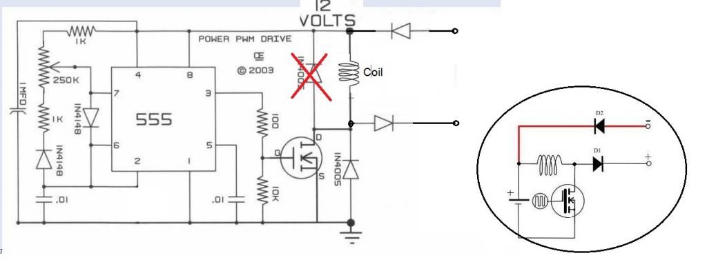
                            Hi all (especially ufo)

                            After reading this post im at the point of starting my own crcuit
                            I decided to start with the 1. version of ufos pwmcircuit.
                            I hope i got it right:

                            1. u need a stable 12v source
                            2. next step is too turn it into a pwm signal and amplify it
                            3. then u use a coil to "filter" out the hot part

                            i hope i got it right because i am a little noob in electronic (only know the basics)
                            that means soldering and connecting or using meters or osciloscope is not the problem

                            The problem for me here in austria however is getting the parts....

                            i only know rs and conrad but i cant find the requierd parts (especially the 555?)

                            plz can anyone link me the parts required from one of these resellers?(its somehow confusing if u dont no the required specs of the parts due too not having the understanding in electronics)

                            thx in advance


                            i want too use this basic scematic first.(i hope thats the way to go)

                            Originally posted by Lester444 View Post
                            Hello UFO,

                            I have edited the circuit diagram to be consistent with the other diagrams in the first few posts. Just trying to avoid confusion with the other members. I hope you don't mind.

                            Lester

                            Comment


                            • Originally posted by kassadum View Post
                              Hi all (especially ufo)

                              After reading this post im at the point of starting my own crcuit
                              I decided to start with the 1. version of ufos pwmcircuit.
                              I hope i got it right:

                              1. u need a stable 12v source
                              2. next step is too turn it into a pwm signal and amplify it
                              3. then u use a coil to "filter" out the hot part

                              i hope i got it right because i am a little noob in electronic (only know the basics)
                              that means soldering and connecting or using meters or osciloscope is not the problem

                              The problem for me here in austria however is getting the parts....

                              i only know rs and conrad but i cant find the requierd parts (especially the 555?)

                              plz can anyone link me the parts required from one of these resellers?(its somehow confusing if u dont no the required specs of the parts due too not having the understanding in electronics)
                              thx in advance
                              i want too use this basic scematic first.(i hope thats the way to go)
                              Hallo kassadum,
                              willkommen im Club! (welcome). Gute Entscheidung! Simple things first!
                              NE555
                              NE555
                              ne555
                              Yes, UFOs circuit is a good start!

                              You may contact "tomturbo80" you might cooperate while living in same region.
                              JohnS
                              Last edited by JohnStone; 02-19-2013, 02:13 PM.
                              Experts spend hours a day in order to question their doing while others stopped thinking feeling they were professionals.

                              Comment


                              • Hi Machine,
                                please check the overvoltage protection at your driver. It was designed for those coolmos FETs. If you use 300V type please short circuit one of those 250V protecting diodes in order to protect your FETs.
                                Check voltge spikes with scope!
                                JohnS
                                Experts spend hours a day in order to question their doing while others stopped thinking feeling they were professionals.

                                Comment

                                Working...
                                X