Announcement

Collapse
No announcement yet.

My Motors got me to Tap into Radiant Energy

Collapse
X
 
  • Filter
  • Time
  • Show
Clear All
new posts

  • Originally posted by prochiro View Post
    Hi tomturbo80
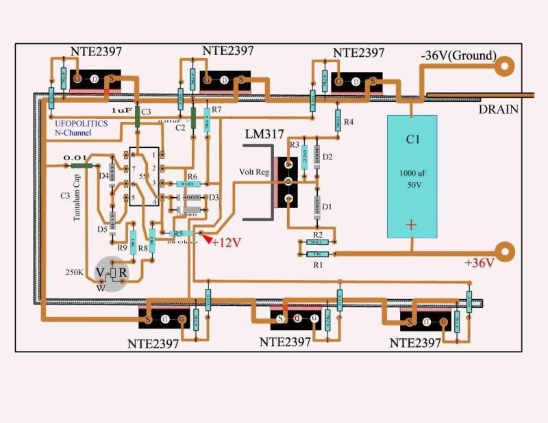
    As I recall that circuit worked as shown. There was two versions of that circuit. The one you should be working on has a wire from D3 running more or less straight down to ground on bottom of picture. Are you using 36 volts? That might make the difference. The 47K's are so high resistance that removing them should not make that much difference unless you had them tied in series rather than parallel. I believe they were to prevent overload as a pull-down to get fets off fast. Check your circuit for any other difference in parts and correct method of wireing. Helping you is our pleasure, just make sure that every posted question keeps us informed of the exact circuit you are working on as JohnStone asked. UFO has gotten a lot of miles on that circuit.
    Dana
    Hello, Dana,
    I thank you for the support. If no Shematic where had till present these Ground connection is marked. Kassadum has to me a shematic with this connection hand over. If I test tomorrow immediately sometimes.
    Thanks
    greets
    tomturbo80

    Comment


    • Originally posted by tomturbo80 View Post
      Hello, Dana,
      I thank you for the support. If no Shematic where had till present these Ground connection is marked. Kassadum has to me a shematic with this connection hand over. If I test tomorrow immediately sometimes.
      Thanks
      greets
      tomturbo80
      G'Day tomturbo80
      Here is the circuit that UFO used and been corrected it works great
      Here it is here
      https://www.dropbox.com/s/ohk45qzffs...ckchisel97.jpg

      and working here

      ------------------------------------------------------
      Kogs Sees The LIGHT Video by Kogs1 | Photobucket

      ----------------------------------------------------------
      Also here
      UFO's Circuit Running a MY1018 - YouTube

      Kogs UFO Happy Motor Circuit - YouTube

      With this UFO happy motor circuit I used the above corrected Controller

      Kindest Regards
      Kogs

      Just trying to help

      Comment


      • Hi iankoglin,
        I am a bit confused therefore I need to sort some items:
        1. Sorry no target file available.
        2. You want to drive a MY.... motor Ufo style?
        3. How many amps do you expect as maximum (full throttle from zero speed) and when cruising (max. sped / max. throttle)
        4. You intend to pulse this motor with one FET stage? Or have you another setup in mind? Why so many FETs. It would be cheaper to buy fewer high amp ones!
        5. I recently posted a simlified (monster) driver with an opto / driver IC and protecting circuitry. There you can add your SG-circuit directly as generator.


        Please note:
        - Those 555 circuits as driver will do fine for lab tests but they are quite slow -> heating FETs. While cruising you have no control for heat.
        - Realizing your intention requires protecting FETs! -> all those components at monster driver around FETs.

        I do not question your plan but I need to know more of your thoughts in order to give qualified advice.
        JohnS
        Experts spend hours a day in order to question their doing while others stopped thinking feeling they were professionals.

        Comment


        • Originally posted by JohnStone View Post
          Hi iankoglin,
          I am a bit confused therefore I need to sort some items:
          1. Sorry no target file available.
          2. You want to drive a MY.... motor Ufo style?
          3. How many amps do you expect as maximum (full throttle from zero speed) and when cruising (max. sped / max. throttle)
          4. You intend to pulse this motor with one FET stage? Or have you another setup in mind? Why so many FETs. It would be cheaper to buy fewer high amp ones!
          5. I recently posted a simlified (monster) driver with an opto / driver IC and protecting circuitry. There you can add your SG-circuit directly as generator.


          Please note:
          - Those 555 circuits as driver will do fine for lab tests but they are quite slow -> heating FETs. While cruising you have no control for heat.
          - Realizing your intention requires protecting FETs! -> all those components at monster driver around FETs.

          I do not question your plan but I need to know more of your thoughts in order to give qualified advice.
          JohnS
          G'Day John
          I really appreciate all you do for us here
          The target files 3 of them are imbedded into the word doc along with the "Fet Driver with 555/ver3" that you drew
          When you showed us this circuit I decided to build it and ordered all of the parts I already had 50 STP11NK4OZ mosfets that I purchased when I was building UFU's 555 driver
          I do intend to build these 2 circuits the SG3525 and the 555 Fet driver to drive a small Mobility scooter motor by Electric Motor Developments in Essex England (There was 2 motor on the Scooter of which I am making into one Modifies asymmetric motor which the specs on the unmodified motor are 24vDC 8 amp RPM 125 (it had a 1:50 gearbox on it) and output 120watts. I want to use this motor to fit on my bicycle.
          Then I want to make a larger driver using the large coil arrangement in my dropbox to drive a ZY 1020F motor 1000w 48vDC 20.8 amp Chinese by ½ð»ªÊнð¶ÙµçÆ÷ÓÐÏÞ¹«Ë¾ I purchased 2 in Aus I want to drive an unmodified motor in a Tricycle I am going to build to see what it can do and after when I am able to get another on (end of March) I will modify the two to an asymmetric motor and then fit into the Tricycle and compare how it goes against the unmodded one.
          By this time I will have enough experience at winding motors to continue on with the P56 Motors of which I will purchase better faster Mosfets and build your Monster Fet driver
          I imagine you mean one Fet stage is 1 Fet driver with 2 Fets On my previous UFO driver there was 8 Mosfets so I was going to build both of my drivers using 4 stages and that is why I asked you Please another question
          With the SG3525 Oscillator How many Opto's do you think I could run and could I use the bottom Opto's or just have more top ones and delete the bottom ones? In Steven Cerovic he had 3 opto's on the top and 4 on the bottom as I imagine I could use this Oscillator to drive probably 8 stage mosfets if required.
          Please John here is the link to my Drop box folder with all the relevant pics of the large coil and T3001 circuits I am talking about


          https://www.dropbox.com/sh/6cy658nuph8vedn/Xaf9ChlXM7

          Kindest Regards


          Still really trying

          Comment


          • Hi iankoglin,
            now I understand.
            But sorry the embedded files in MS Word do not open at my location.

            Regrading your setup.
            - Generator SG...circuit with 2 times 4 optos
            - driver 555 with transistors
            - FETs: please regard them to be rated for 5.6A at 100°C!!!!! and 0.5Ohm each. You might devise tests with pure resistiver loads (see my recent posts regarding car head lamps being pulsed) in order to see how your setup behaves with 2 FETs (pease connect them similar to the monster driver (gates to be close together). Check for temperature at 10.
            JohnS
            Experts spend hours a day in order to question their doing while others stopped thinking feeling they were professionals.

            Comment


            • Some advice on the motor control circuit(s)

              UFO, Ian, Tomtom, or JohnS

              Planning to move out of the toy motor size soon and looking at circuits. I am not getting the picture on John Stones monster driver yet, seems to contain new oscillator circuits, voltage regulation, amplification? I would hopefully be able with my levels of expertise in the various skills needed to maybe avoid starting at the basic UFO circuit at the beginning to understand the harvesting of Radiant energy. But maybe not. I would like to use some intermediate level circuit maybe to drive my RS replications. My plan involves one level up from the toy level. I have 4 motors with rotors the size of my palm I would like to wind, 10 poles, perhaps a generator style on one, very interested in making them an 8 brush motor like the Imperial. I can't justify investing a $1000 in an Imperial project until I convince myself I can build it. So for now I would like build a smaller series of motors and an intermediate driver circuit. Perhaps the UFO circuit instead of the monster driver circuit. I think operation in the few ampere range is adequate for next size motors. I don't understand why the UFO circuit is using 6 mosfets, is that just to be able to handle large current sizes of the imperial motor, and handles current in parallel, just adding them up to handle an imperial size motor? So for my next phase I won't be running at 36v(12, maybe 24), or at the higher amps. I am thinking I have a lot of parts on hand. For instance I have a MOSFET C5353, HV, operating at a lower 3 amp range. Surely I can get to work substituting parts on hand. Can I just use less mosfets and different types on the Blackchisel corrected UFO circuit? This was posted on P61, I think it is the Ufo circuit, but do not understand the latest correction yet. A quick point would be appreciated if it is not up to date.

              Thanks all and happy motoring!
              Attached Files
              Up, Up and Away

              Comment


              • Hi Sampojo,
                the monster driver is just waht it says - a driver. It can be contolled by any PWM oscillator - including micros. The driver makes use of current technology including powerful FET drivers and super FETs. Thus if you use standard FETs you require to connect several to one driver.
                If you hesitate to spend money for 2 Infineon FETs you can use 2 or four quite normal ones and replece them later on.
                Else follow recent posts utilizing 555 and transistors.

                My personal decision was to build a driver only once. Thus I developed it and shared it.

                My advice is to crowd up for 555 type or monster driver type and not add additional trials.
                But there are plenty of other possibilities available. Unfortunately we can not help in any case of very unusual setups.
                JohnS
                Experts spend hours a day in order to question their doing while others stopped thinking feeling they were professionals.

                Comment


                • Thanks John Sone & coil question

                  So on the 555 ciruit, the mosfets appear bussed. Are they sharing current load then? So if I am building a smaller motor operating at a low current range compared to the Imperial, I could use fewer correct?.

                  Coil question: at the start of this thread, a large coil was used to generate RE.

                  I have seen some mention of a coil used recently here, maybe with a motor controller, but cannot find any specs. Is one being used to help feed the motor and where are the latest recommended specs, just an approximate point would be great.

                  But then on post 1640 and 1618 Ufo indicates we are using the motors coils instead. so it is just one of the motor hook-ups to the board then.
                  Last edited by sampojo; 02-24-2013, 11:43 PM. Reason: sp
                  Up, Up and Away

                  Comment


                  • Originally posted by sampojo View Post
                    So on the 555 ciruit, the mosfets appear bussed. Are they sharing current load then? So if I am building a smaller motor operating at a low current range compared to the Imperial, I could use fewer correct?.

                    Coil question: at the start of this thread, a large coil was used to generate RE.

                    I have seen some mention of a coil used recently here, maybe with a motor controller, but cannot find any specs. Is one being used to help feed the motor and where are the latest recommended specs, just an approximate point would be great.

                    But then on post 1640 and 1618 Ufo indicates we are using the motors coils instead. so it is just one of the motor hook-ups to the board then.
                    Yes, you may start with fewer FETs. But you need to do the spacing before for full count of FETs.
                    It is essential to:
                    - have connections from driver to FETs equal length or use a bus bar feeding in the center.
                    - an individual GND wire from driver GND to source pins of FETs or use a bus bar feeding in the center.
                    - connect drains equal length, thick wire to a central PMWout screw (or pin)
                    - dto. source pins

                    Different from transistors, FETs may be paralleled because they increase their resistance (DS) along heat. So they distribute loads equally - but only if you provide measures suggested above.

                    The measures above might be omittet for low loads. If you approach to maximum you will suffer losses of FETs or performance.
                    Imagine a sophisticated street racing car and you drive it across a field. You might arrive your destination if you drive slowly and gently. But if you drive it at full power - like at road quality intended - you will loose!

                    Consider current at FETs to be rated half of maximum at 100°C.
                    Consider full on state to be above 10V at gate at high currents. Do not be fooled by looking at the lower voltage where FET starts opening the door!
                    The properties are tied together and it is essential to get them balanced. It is like at a chain - any weak link will affect the success totally.

                    ~o0o~

                    Coil construction was discussed in excess at beginning of this thread . 1 Ohm is recommended. You can use thick wire and then you can apply more windings for better performance. You should be able to test with and without ferrous core.

                    Begin any setup with car bulb in series in order to protect distruction by current being excessive. And begin it with low duty percentage for same resason.

                    The setups with coil only are for intriductory work. Later we replaced them by real motors. Nevertheless some tests can be done with motors and coils. But this is not the main stream intended.
                    Experts spend hours a day in order to question their doing while others stopped thinking feeling they were professionals.

                    Comment


                    • Originally posted by sampojo View Post
                      UFO, Ian, Tomtom, or JohnS

                      Planning to move out of the toy motor size soon and looking at circuits. I am not getting the picture on John Stones monster driver yet, seems to contain new oscillator circuits, voltage regulation, amplification? I would hopefully be able with my levels of expertise in the various skills needed to maybe avoid starting at the basic UFO circuit at the beginning to understand the harvesting of Radiant energy. But maybe not. I would like to use some intermediate level circuit maybe to drive my RS replications. My plan involves one level up from the toy level. I have 4 motors with rotors the size of my palm I would like to wind, 10 poles, perhaps a generator style on one, very interested in making them an 8 brush motor like the Imperial. I can't justify investing a $1000 in an Imperial project until I convince myself I can build it. So for now I would like build a smaller series of motors and an intermediate driver circuit. Perhaps the UFO circuit instead of the monster driver circuit. I think operation in the few ampere range is adequate for next size motors. I don't understand why the UFO circuit is using 6 mosfets, is that just to be able to handle large current sizes of the imperial motor, and handles current in parallel, just adding them up to handle an imperial size motor? So for my next phase I won't be running at 36v(12, maybe 24), or at the higher amps. I am thinking I have a lot of parts on hand. For instance I have a MOSFET C5353, HV, operating at a lower 3 amp range. Surely I can get to work substituting parts on hand. Can I just use less mosfets and different types on the Blackchisel corrected UFO circuit? This was posted on P61, I think it is the Ufo circuit, but do not understand the latest correction yet. A quick point would be appreciated if it is not up to date.

                      Thanks all and happy motoring!
                      G;Day sampojo
                      They may be toy size motors BUT they are for learning UFO did not ask people to buy $100 or $600 motors to show and explain what he wanted to disclose to us In the first instance when the Naysayers /trouble makers arrived UFO spat the dummy he removed all his drawings and Videos from the forum and said he was not going to continue with all the CRAP being flung at him.
                      But after many of us pleaded for him to continue he did continue of which all those who beleived in what he was disclosing to us and others that have joined here are TRULY APPRECIATIVE of.

                      UFO had firstly showed us how we can use this technology to run a normal DC motor Those drawings were the ones that he did remove and were not reloaded the ones that are still on display are the ones that others included in thier posts.
                      This one is the corrected UFO's Mosfet driver he said he uses this one to run all his motors

                      https://www.dropbox.com/s/rlm9u90bnf...ckchisel97.jpg

                      This one is what he called his happy motor it is a more intuitive one than the one you have posted I did not have that one saved so I cannot display it but this one UFO said will run any DC motor provided you make the coils to match the motor you want to run

                      https://www.dropbox.com/s/w7dij44pqf...appy-motor.jpg

                      The next one is my rendition/build of his happy Motor

                      https://www.dropbox.com/s/rlj9hhii7p...HappyMotor.jpg

                      Thisdrawing is the way I built UFO's Happy Motor
                      He called it a Happy Motor because it will run a normal DC motor with Radiant Energy and this is without the motor getting Hot I ran my 250watt motor using this circuit it only always drew 200ma from the 36v (3 x 12v) car batteries but I was running this motor with up to 90V see it here

                      UFO's Circuit Running a MY1018 - YouTube

                      I tried to run a 1000w chinese motor with this circuit but the mosfets and coil got hot So I have made a larger coil and improving my Mosfet driver to match the motor I will let everyone know how it goes when I finish it

                      Also I used this same setup to light 5 CFL bulbs see it here

                      Kogs UFO Happy Motor Circuit - YouTube

                      Kindest Regards Kogs


                      Just being Helpful

                      Comment


                      • Hello nico8k,


                        I am currently replicating Sir JohnS's Monster Driver V5.1 and want to use an Arduino as my oscillator.

                        Have been looking at several Utoops,

                        Tutorial 01 for Arduino: Getting Acquainted with Arduino
                        Tutorial 02 for Arduino: Buttons, PWM, and Functions
                        Tutorial 03 for Arduino: ElectricalEngineering Basics

                        Tutorial 04 for Arduino: Analog Inputs
                        Tutorial 05 for Arduino: Motorsand Transistors
                        Tutorial 06 for Arduino: SerialCommunication and Processing

                        Tutorial 07 for Arduino: I2CCommunication and Processing
                        Tutorial 08 for Arduino: SPIInterfaces
                        Tutorial 09 for Arduino: WirelessCommunication

                        Tutorial 10 for Arduino: Interruptsand Hardware Debouncing
                        Tutorial 11 for Arduino: SDCards and Datalogging
                        Tutorial 12 for Arduino: RFIDCard Reading

                        Tutorial 13 for Arduino: LiquidCrystal Displays (LCDs)
                        Tutorial 14 for Arduino: HolidayLights and Sounds Spectacular!
                        Tutorial 15 for Arduino: GPSTracking

                        Everything You Need To Know About Arduino

                        and have put togeather some code, however programing isn't my first language and rather than reinvent the wheel
                        thought you would already have the code worked up for 2 pots in, freq & duty cycle, with one LED output and LCD display of both.

                        I have the hardware togeather and can see the pots changing value but must have missed a comma


                        You seem to be the Arduino goto person in this group,
                        any help would be most appreciated, Thank you


                        Regards

                        Hitby13kw

                        Comment


                        • Arduino Code

                          Hello Hitby13kw
                          You have entered a lot of good videos here but have not read nico8k post number 3923. Both he and I use push buttons instead of pot as it is much more accurate in both frequency selection and duty cycle selection as well as a better tighter square wave. He shows how to put it on a breadboard in post 3923 and here I have a picture of it on top level of arduino. Note the simplicity.
                          http://i1079.photobucket.com/albums/...psdf4a27bb.jpg
                          Dana
                          Last edited by prochiro; 02-25-2013, 11:36 PM. Reason: forgot link
                          "Today's scientist have substituted mathematics for experiments and they wander off through equation after equation and eventually build a structure which has no relation to reality."
                          Nikola Tesla

                          Comment


                          • Thanks Kogs!

                            Originally posted by iankoglin View Post
                            G;Day sampojo ...
                            They may be toy size motors BUT they are for learning UFO did not ask people to buy $100 or $600 motors to show and explain what he wanted to disclose to us
                            My reservations on sinking the money on high power motors is hopefully only temporary and comes only from limitations of my time, electronics skills, and electric motor knowledge and skills, which I am progressing on. Every free moment off my full time job is going toward this. Thanks so much for any repeat information. I spend much time slogging thru the randomness of thread based technical information but still cannot find some things.

                            This one is what he called his happy motor ... because it will run a normal DC motor with Radiant Energy
                            This is exactly what I was looking for. Thanks immensely. What genius! I had been just reading between lines on posts referring to coils surmising that this is what Ufo was doing. I couldn't imagine where to start hooking things up.

                            Just being Helpful
                            Yes indeed, Ian

                            So, Ufo has posted that the plan was to use the coil motors as opposed to an additional (simple non-twisted bifilar, I think?) coil. Probably the generator side of a motor and/or the generator coils in a motor-generator hookup. But where on the Blackchisel updated Ufo circuit would the coil be hooked up?

                            CORRECTED as pointed out by Ian a few posts ahead!!


                            So it is intriguing to me to use the additional coil and I have read a post recently where he has recommended steel core over air core. Should I take that as the best in all cases, do you know? The motor goes to the +12v and ground I suppose? Is this wrong? Would that be because radiant is introduced? On his videos of some motor tests, no controller were yet introduced but that meant a full 36v was being applied.

                            Where would a controller be inserted in the happy motor dgm?


                            I feel like I have to pinch myself once in a while to make sure I am not in some sort of fairy tale dream about free energy

                            I will understand if I am like the kid with 20 questions...

                            TIA
                            Attached Files
                            Last edited by sampojo; 03-13-2013, 07:45 PM. Reason: add pic
                            Up, Up and Away

                            Comment


                            • G'Day sampojo

                              My reservations on sinking the money on high power motors is hopefully only temporary and comes only from limitations of my time, electronics skills, and electric motor knowledge and skills, which

                              Finish learning with small motors then when you understand go on to bigger motors

                              This is exactly what I was looking for. Thanks immensely. What genius! I had been just reading between lines on posts referring to coils surmising that this is what Ufo was doing. I couldn't imagine where to start hooking things up.

                              Don't read between the lines as there is nothing there As you read make sure you understand do not surmise ask Questions

                              Yes indeed, Ian

                              So, Ufo has posted that the plan was to use the coil motors as opposed to an additional (simple non-twisted bifilar, I think?)

                              NoNoNo the Happy motor circuit is made up of a bifilar coil in the first instance they both measure 1 Ohm this Happy Motor circuit Diagram will run a normal DC motor also a Assymetric motor

                              But where on the Blackchisel updated Ufo circuit would the coil be hooked up?

                              You need 36v to run this circuit.
                              Where to connect it up Look at my Kogs Happy motor this circuit is made up of a bifilar coil, I seperated them just to show how they are connected using the Diodes Note there is a regulator an Oscillator and a Mosfet circuit These are the components that are in UFO's controller I built separate units so I could test each part of the circuit so as to understand them My regulator is 40v to 12v regulator because my 12v car batteries rest at 13v each and I did not want to blow anything upAlso the diodes and the Mosfets NEED TO BE FAST ONES as shown in UFO's /Blackchisel's circuit study both UFO's Controller and my Happy motor to see just where everything fits


                              So it is intriguing to me to use the additional coil and I have read a post recently where he has recommended steel core over air core. Should I take that as the best in all cases, do you know? The motor goes to the +12v and ground I suppose? Is this wrong? Would that be because radiant is introduced? On his videos of some motor tests, no controller were yet introduced but that meant a full 36v was being applied.

                              Air or steel all depends on the application Don't worry about these other things just build as shown and when you get it going DO NOT USE IT FOR ANY OTHER THING keep it whole for your own reference,Also the controller is for 36v even to run a 12v or 36v motor

                              Where would a controller be inserted in the happy motor dgm

                              Read My answer above

                              I will understand if I am like the kid with 20 questions...

                              The best way is the internet there is the answer to most questions after trying there then ask no worries

                              Kindest Regards Kogs

                              Just trying to be helpful
                              Last edited by iankoglin; 04-03-2013, 11:09 PM. Reason: Wrong Pic

                              Comment


                              • Hi iankoglin,
                                in your vid the circuit diagram of happy motor is not clear. Did you post it already anywhere. I'd like to review your setup in order to gather knowledge.
                                Thanks
                                JohnS
                                Last edited by JohnStone; 02-26-2013, 10:00 PM.
                                Experts spend hours a day in order to question their doing while others stopped thinking feeling they were professionals.

                                Comment

                                Working...
                                X