Announcement

Collapse
No announcement yet.

My Motors got me to Tap into Radiant Energy

Collapse
X
 
  • Filter
  • Time
  • Show
Clear All
new posts

  • John

    Could it be some older russian transistors has the ability to switch current faster then documented and thus pass many amperes better then mosfets ? I wonder because I heard Kapanadze used a pair of such old transistors...
    Just curious if that's an urban myth or not

    Comment


    • ignor me, just trying to get this in my SUBSCRIBED mail

      hi
      bye
      yes following, lost but working on it. TY
      Last edited by BobBrown; 03-06-2013, 04:12 PM.

      Comment


      • Monster of an idea

        @JohnStone
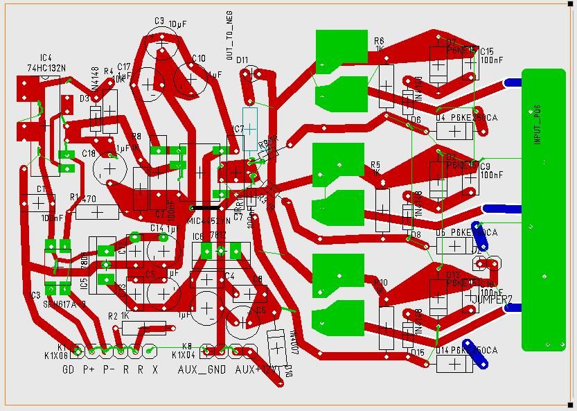
        John, please do not consider this in a negative way. I have built a number of the circuits not and when some wires get to touching others, well you know what happens. I was thinking about how to get the high power in and out without covering the rest of the circuit and make it easy to repair. I was also just seeing if a third fet would fit as machine was talking about. Not that I will do it but just toying with things. This circuit is also not to be followed thru to a build by anyone... What I wanted to suggest is a possible way of mounting the board over another fixture and using eight bolts to tie the two parts electrically and support wise together. The bolts would carry strong current to below where large wires could be out of the way and yet do the job. Just consider the idea as it may be easier to replace each board as well as support it at the same time. Just an idea.

        Dana
        "Today's scientist have substituted mathematics for experiments and they wander off through equation after equation and eventually build a structure which has no relation to reality."
        Nikola Tesla

        Comment


        • Arduino vs DDS function generator?

          I recently built a circuit that takes an AC square wave from an audio program from my computer, clips off the top portion and uses the signal to switch some transistors, which then switch some high power fets to pulse my motor. I am wondering what you guys thing of DDS function generators....Some can be controlled with a computer and have pretty good functionality.

          40MHz DDS Function Signal Generator Module SPI I2C Master Slave Pulse Generator | eBay

          Have a look at this one and let me know if you see any problems with it running a motor. I will have a voltage regulator or 2 different power supplies...one to switch my transistors across the fets and one across my fets to my motor. I have been using this lately and its been working great, however the audio range it puts off is below 22khz....something faster would be interesting for trying to get more radiant out....

          Comment


          • @warrensk
            That will work well and has pattern train pulse which we are are not into but may be handy. There are much cheaper as in Arduino and such also The only thing that is important is that we start with a clean wave at about 5 volts and that it has the range we seek. Total control weather manual or programed in important.
            Dana
            "Today's scientist have substituted mathematics for experiments and they wander off through equation after equation and eventually build a structure which has no relation to reality."
            Nikola Tesla

            Comment


            • Originally posted by prochiro View Post
              @JohnStone
              John, please do not consider this in a negative way. I have built a number of the circuits not and when some wires get to touching others, well you know what happens. I was thinking about how to get the high power in and out without covering the rest of the circuit and make it easy to repair. I was also just seeing if a third fet would fit as machine was talking about. Not that I will do it but just toying with things. This circuit is also not to be followed thru to a build by anyone... What I wanted to suggest is a possible way of mounting the board over another fixture and using eight bolts to tie the two parts electrically and support wise together. The bolts would carry strong current to below where large wires could be out of the way and yet do the job. Just consider the idea as it may be easier to replace each board as well as support it at the same time. Just an idea.


              Dana
              Hi Dana,
              don't worry! Any suggestion is welcome.
              The implicaytion is that everybody is free to use different heat sinks and other means. We can stop this by selling a kit with all components required - but sorry - not possible.
              Your suggestion is viable but lots of members will do it other way.
              At high currents it is a limit where PCBs can not be applied.
              Therefore I suggest leave PCB as is and explore its performance.

              Going beyound I recommend:
              - build PCB with control circuit only-
              - mount FETs on preferred heat sink along massive bus bars conformung current requirements (see my posts some pages before)
              - Attach protection circuit flying "3D" type or on small PCB to bus bars
              - Attach control board by short wires and mount it on heat sink

              I appreciate your suggestion but in order to not generate plenty of different and additional solutions I recommend to do FET wiring off PCB.
              JS
              Last edited by JohnStone; 03-07-2013, 10:57 AM.
              Experts spend hours a day in order to question their doing while others stopped thinking feeling they were professionals.

              Comment


              • Originally posted by warrensk View Post
                I recently built a circuit that takes an AC square wave from an audio program from my computer, clips off the top portion and uses the signal to switch some transistors, which then switch some high power fets to pulse my motor. I am wondering what you guys thing of DDS function generators....Some can be controlled with a computer and have pretty good functionality.

                40MHz DDS Function Signal Generator Module SPI I2C Master Slave Pulse Generator | eBay

                Have a look at this one and let me know if you see any problems with it running a motor. I will have a voltage regulator or 2 different power supplies...one to switch my transistors across the fets and one across my fets to my motor. I have been using this lately and its been working great, however the audio range it puts off is below 22khz....something faster would be interesting for trying to get more radiant out....
                DDS is the recent technology. Usually those modules do not emit PWM at all (50% duty only). This module has built in pulse generation but up to 20KHz. That indicates it omits DDS generator and does it by micro only.
                This module can surely be used but there is programming overhead required we can not support here in forum.

                Summed up:
                • usable: YES
                • public recommendation for easy use: no
                Experts spend hours a day in order to question their doing while others stopped thinking feeling they were professionals.

                Comment


                • sounds good to me!

                  Thanks guys!

                  I want to use it as a square wave generator and use it instead of my computer's audio signals. Cleaning up the wave form shouldn't be too hard, when the transistors switch they make a nice solid square wave to then switch the fets. I've come to learn why everything needs a common ground, that's for sure. I'll be sure to post updates when I get it going again on some higher voltages.

                  Warrensk

                  Comment


                  • concept question regarding PWM on Asym motor

                    Hi all, whoever can answer, probably John!

                    S1: Whenever we hook a battery directly to a motor and run it flat out, the commutators do the pulsing to the coils of course and the generator coil gets to harvest the back emf pulse soon after a coils rotates off the motor brushes and gets to the generator brushes. (T/F?)

                    S2: Inserting a PWM, it controls power input by pulsing the current to the motor. Apparently the monster Pulser has frequency control and pulse width control which will vary the width from 0~ to 100% of any given frequency cycle. (T/F?)

                    My question is about an idea of synchronizing the the frequency of pulse action with the motor rpm. I am wondering if there is any detrimental action if the pulse action is not in sync with the rpm, more precisely B]NO MORE THAN[/B] one pulse per COMMUTATOR SEGMENT. Wouldn't multiple trailing edges within a commutator segment put radiant energy in a symmetric-type situation where it will be fighting the leading edge, hot electricity pulses?

                    When you guys are using the PWM now do you operate at frequencies well under RPM x #commutator segements? Imperial has 36? 36x5000rpm=180kcs, as a nominal value.

                    Does the Monster pulser have the ability to get its frequency setting from a hall switch measuring motor rpm and then get its timing from the motor?
                    Up, Up and Away

                    Comment


                    • concept question regarding PWM on Asym motor

                      Hi all, whoever can answer, probably John!

                      S1: Whenever we hook a battery directly to a motor and run it flat out, the commutators do the pulsing to the coils of course and the generator coil gets to harvest the back emf pulse soon after a coils rotates off the motor brushes and gets to the generator brushes. (T/F?)

                      S2: Inserting a PWM, it controls power input by pulsing the current to the motor. Apparently the monster Pulser has frequency control and pulse width control which will vary the width from 0~ to 100% of any given frequency cycle. (T/F?)

                      My question is about an idea of synchronizing the the frequency of pulse action with the motor rpm. I am wondering if there is any detrimental action if the pulse action is not in sync with the rpm, more precisely NO MORE THAN one pulse per COMMUTATOR SEGMENT. Wouldn't multiple trailing edges within a commutator segment put radiant energy in a symmetric-type situation where it will be fighting the leading edge, hot electricity pulses?

                      When you guys are using the PWM now do you operate at frequencies well under RPM x #commutator segements? Imperial has 36? 36x5000rpm=180kcs, as a nominal value.

                      Does the Monster pulser have the ability to get its frequency setting from a hall switch measuring motor rpm and then get its timing from the motor?
                      Up, Up and Away

                      Comment


                      • Originally posted by sampojo View Post
                        ...My question is about an idea of synchronizing the the frequency of pulse action with the motor rpm. I am wondering if there is any detrimental action if the pulse action is not in sync with the rpm, more precisely B]NO MORE THAN[/B] one pulse per COMMUTATOR SEGMENT. Wouldn't multiple trailing edges within a commutator segment put radiant energy in a symmetric-type situation where it will be fighting the leading edge, hot electricity pulses?
                        Does the Monster pulser have the ability to get its frequency setting from a hall switch measuring motor rpm and then get its timing from the motor?
                        1. Monster pulser or any other can be controlld by any means.

                        2.You are right! That is the question - do we need synchronisation? Probably it was not tested before. Probably beats will result from different freqeuncies being mixed (rpm and pulsing) Unfortunately my motor building needs to wait a time. We will surely test it one time. There are plenty of tests to be done. We presnetly search in dark room for a kind of topology at floor.

                        But please do not think in terms of stadard knowledge - it wil cheat you.
                        We do not know what, where and how energies flow while motor coil pulsed. Perhaps it is not relevant exactly when we pulse. I understand UFOs motor as a setup getting rid of some flaws covering true elecricity effects. Thus it is a preferred research motor and does not hide effects we are after. It helps studying all those free energy setups out there - you will find common rules they apply - a set of tools!

                        Electicity seems to be not so simple as we learned by our teachers. I comprehend standard knowledge as a tent. It seems to be a solid volume but if you touch it you need to search for a solid tube below the fabric. Nevertheless it is a useful device - a tent and not mre - but not the whole trooth of architecture.

                        Nowadays flowing current is the omnipresent art to use electricity. It is like high noon whith sun shining bright and we do not see any star. We killed all side effects in order to destillalte the currently known electricity - current flow.
                        If you want to have water available in your home you need a well and a bucket or pipeline in order to carry it there to.
                        Now, comprehend those motors (similar to Bedini SSG) as the well we have digged. That is one side of a coin only - very effitient motors - but we search for a means for harvesting anf carrying home - research one!
                        We are after those additional emanations of electricity we want to study at these motors.
                        There are more effects being reported like magnetic resonance, adapting load to motor impedance, reactive power, resonance, steep HV pulses, magnetic attraction.... We need to study them - based on those coils and motors.

                        Did anyone care on resonance effects at asymmetric motors? Any winding will resonate with natural frequency after loosing contact to power drive. It needs to be studied. This resonating coil craseis to generator brushes. What happens to that stored energy and reacitve power? It needs to be explored.

                        We are in stone age. Iron was there since ages, since creation - we need to discover it.

                        Please excuse if I am too verbose. I just share my comprehension and share where I try to dig next.

                        Back to your questions, sampojo! They are smart and need to be tested out. But there is far more to it. We need to see the whole bunch of chances.

                        And in the end a tiny answer: There is no means known switching faster than a mechanic commutator - I remeber 10ns. No current pulser will be faster.
                        JS
                        Last edited by JohnStone; 03-07-2013, 10:08 PM.
                        Experts spend hours a day in order to question their doing while others stopped thinking feeling they were professionals.

                        Comment


                        • Digging is good for you.

                          Originally posted by JohnStone View Post
                          1. Monster pulser or any other can be controlld by any means.

                          2.You are right! That is the question - do we need synchronisation? Probably it was not tested before. Probably beats will result from different freqeuncies being mixed (rpm and pulsing) Unfortunately my motor building needs to wait a time. We will surely test it one time. There are plenty of tests to be done. We presnetly search in dark room for a kind of topology at floor.

                          But please do not think in terms of stadard knowledge - it wil cheat you.
                          We do not know what, where and how energies flow while motor coil pulsed. Perhaps it is not relevant exactly when we pulse. I understand UFOs motor as a setup getting rid of some flaws covering true elecricity effects. Thus it is a preferred research motor and does not hide effects we are after. It helps studying all those free energy setups out there - you will find common rules they apply - a set of tools!

                          Electicity seems to be not so simple as we learned by our teachers. I comprehend standard knowledge as a tent. It seems to be a solid volume but if you touch it you need to search for a solid tube below the fabric. Nevertheless it is a useful device - a tent and not mre - but not the whole trooth of architecture.

                          Nowadays flowing current is the omnipresent art to use electricity. It is like high noon whith sun shining bright and we do not see any star. We killed all side effects in order to destillalte the currently known electricity - current flow.
                          If you want to have water available in your home you need a well and a bucket or pipeline in order to carry it there to.
                          Now, comprehend those motors (similar to Bedini SSG) as the well we have digged. That is one side of a coin only - very effitient motors - but we search for a means for harvesting anf carrying home - research one!
                          We are after those additional emanations of electricity we want to study at these motors.
                          There are more effects being reported like magnetic resonance, adapting load to motor impedance, reactive power, resonance, steep HV pulses, magnetic attraction.... We need to study them - based on those coils and motors.

                          Did anyone care on resonance effects at asymmetric motors? Any winding will resonate with natural frequency after loosing contact to power drive. It needs to be studied. This resonating coil craseis to generator brushes. What happens to that stored energy and reacitve power? It needs to be explored.

                          We are in stone age. Iron was there since ages, since creation - we need to discover it.

                          Please excuse if I am too verbose. I just share my comprehension and share where I try to dig next.

                          Back to your questions, sampojo! They are smart and need to be tested out. But there is far more to it. We need to see the whole bunch of chances.

                          And in the end a tiny answer: There is no means known switching faster than a mechanic commutator - I remeber 10ns. No current pulser will be faster.
                          JS


                          Hello John Stone, i'm sure you are not too Verbose, please keep digging, i am sure we are all following with great interest.

                          Some of my testing on the UFO MAG3 design will include switching stator and rotor pulses, through the Monster driver with vane hall sensor on motor shaft, and i am also contemplating, testing, a third commutator for switching stator coils.

                          The tiny sparking at brush contact with commutator, i think adds energy, or helps with resonance, maybe!

                          Hope everyone is keeping well, Regards Cornboy.

                          Comment


                          • Hello Sampojo, Hello All

                            Originally posted by sampojo View Post
                            Hi all, whoever can answer, probably John!

                            S1: Whenever we hook a battery directly to a motor and run it flat out, the commutators do the pulsing to the coils of course and the generator coil gets to harvest the back emf pulse soon after a coils rotates off the motor brushes and gets to the generator brushes. (T/F?)
                            Hello Sampojo, Hello to All,

                            The above statement is True, however, we still have "problems"...generator gates do NOT pick Up/collect ALL Energy...and that IS a problem, and it gets worst by increasing speed...because, if it is not picked up in a higher percentage then we get it crashing at Input Gates, therefore showing a very High Amperage "presence"...that is why we have to play with the angles where to locate the output brushes, till we find a suitable angle...plus, we need to have a Cap Bank at Output gates to collect and store charges...or a load.

                            S2: Inserting a PWM, it controls power input by pulsing the current to the motor. Apparently the monster Pulser has frequency control and pulse width control which will vary the width from 0~ to 100% of any given frequency cycle. (T/F?)

                            My question is about an idea of synchronizing the the frequency of pulse action with the motor rpm. I am wondering if there is any detrimental action if the pulse action is not in sync with the rpm, more precisely B]NO MORE THAN[/B] one pulse per COMMUTATOR SEGMENT. Wouldn't multiple trailing edges within a commutator segment put radiant energy in a symmetric-type situation where it will be fighting the leading edge, hot electricity pulses?
                            Ok, picture the way a Gas Engine works...You depress accelerator, then fuel mixture gets to flow to explosion chambers...and engine raises RPM...now, REALIZE that all cylinders, valves, and sparking are designed at an "SPECIFIC TIMING" in order that Engine is always ready at any time to receive either "more or less" gas mixture flow (mixture, cause we all know it always mix it with air, no matter Diesel or Gas...so "Fuel" is a general term)...and its response would be a lesser or higher RPM.

                            So now, our Asymmetrical Motor is conceived (so far) just like a Fuel Engine I described above...and our "Fuel Supply" is our Monster Pulser, Oscillator/Controllers...

                            Now, related to Radiant Energy here...really forget it, when we are running at very high RPM's...SHE "Vanishes"...becomes very weak...remember, both Energies work Inversely and not that proportional either...but, still...the more Hot...the less Radiant flow.

                            Hope you see my point here.

                            When you guys are using the PWM now do you operate at frequencies well under RPM x #commutator segments? Imperial has 36? 36x5000rpm=180kcs, as a nominal value.

                            Does the Monster pulser have the ability to get its frequency setting from a hall switch measuring motor rpm and then get its timing from the motor?
                            We absolutely could get "fancier" in Distribution/Consumption Protocols, however, for standard applications, where RPM's are not a critical and accurate response requirement...there is no need to go into sophisticated controller designs...and I am referring to EV's app or running a Generator Head...

                            Before I have posted about this "Communication Protocol Networking"...and yes we could be able to "Sync" our supply with Machine RPM's...and it is fairly simple...we get a "signal" right out of our Generator Gates...a low amperage signal that could be read in Hertz...as we could easy install a speed sensor at back shaft (many motors have that "Universal kit" available) in order to process our "Data Flow" [Hertz/RPM's] back to the Supply or Input side...then we get I/O looped and processed.

                            So far we have been playing with Machines that run "Ad Libitum" (Randomly) as we feed them...just like any typical motor out there, however, Asymmetrical Systems allow Us to also play with very accurate networks (I cited that aspect on my ABSTRACT in my first Post on the Motors Thread), like when getting into Servo Motor for Robotics applications.

                            And, by the way, Imperial have 28 Poles at rotor, 56 Elements in Commutators...

                            Regards


                            Ufopolitics
                            Last edited by Ufopolitics; 03-08-2013, 05:07 AM.
                            Principles for the Development of a Complete Mind: Study the science of art. Study the art of science. Develop your senses- especially learn how to see. Realize that everything connects to everything else.― Leonardo da Vinci

                            Comment


                            • So it is "Not Enough Uh?"

                              Originally posted by Cornboy 555 View Post
                              Hello John Stone, i'm sure you are not too Verbose, please keep digging, i am sure we are all following with great interest.

                              Some of my testing on the UFO MAG3 design will include switching stator and rotor pulses, through the Monster driver with vane hall sensor on motor shaft, and i am also contemplating, testing, a third commutator for switching stator coils.

                              The tiny sparking at brush contact with commutator, i think adds energy, or helps with resonance, maybe!

                              Hope everyone is keeping well, Regards Cornboy.

                              Hello Cornboy, my dear friend,

                              So, it seems that MAG3 does not give you enough "possibilities" and then ...you are going to add a third commutator to run stators?!...

                              In my humble opinion...run it simple first...pulse them equally like I stated in previous diagrams...just 3X3...(Three Stators/Three Input Gates) then see/observe what happens...
                              Take Measurements of every kind available...Output through the exhausting other 3 gates...RPM's, Torque...Amperage In-Out...etc,etc


                              I believe you will have your "hands full" my dear friend...


                              Regards


                              Ufopolitics
                              Principles for the Development of a Complete Mind: Study the science of art. Study the art of science. Develop your senses- especially learn how to see. Realize that everything connects to everything else.― Leonardo da Vinci

                              Comment


                              • Hands So Full, can hardly lift them.

                                Originally posted by Ufopolitics View Post
                                Hello Cornboy, my dear friend,

                                So, it seems that MAG3 does not give you enough "possibilities" and then ...you are going to add a third commutator to run stators?!...

                                In my humble opinion...run it simple first...pulse them equally like I stated in previous diagrams...just 3X3...(Three Stators/Three Input Gates) then see/observe what happens...
                                Take Measurements of every kind available...Output through the exhausting other 3 gates...RPM's, Torque...Amperage In-Out...etc,etc


                                I believe you will have your "hands full" my dear friend...


                                Regards


                                Ufopolitics


                                Probably more than full, UFO, and the possibilities seem endless, and make no mistake, i will be as thorough as i can be while moving on.

                                Shylo's comment on other thread is also interesting!


                                Very warm Regards MY friend,

                                Cornboy.
                                Last edited by Cornboy 555; 03-08-2013, 07:27 AM.

                                Comment

                                Working...
                                X