Announcement

Collapse
No announcement yet.

My Motors got me to Tap into Radiant Energy

Collapse
X
 
  • Filter
  • Time
  • Show
Clear All
new posts

  • Dc to dc boost converter

    @ all

    Hey guys, I was thing about adding a DC to DC Boost Converter from the battery pack for the Fire Blade AMEV1.

    Ideas and thoughts please?!

    Keep it Clean and Green
    Richie
    Comment


    • John Stone questions about alternate PCB effort and other

      HI John Stone, welcome back and hope your wife is doing well.

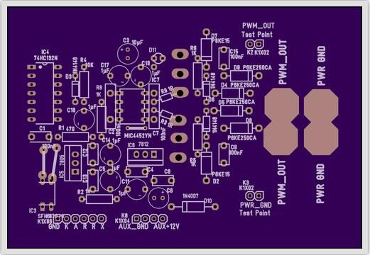
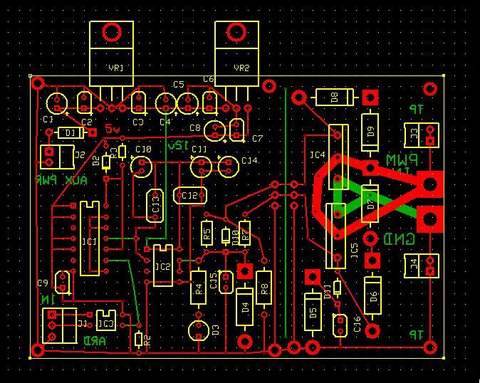
      I had been working on using ExpressPCB as a source of prototype boards until a member pointed out OSHPark, and I submitted your gerber files to them. ExpressPCB does not use gerber files from customers. So I had attempted to use their software to make a similar PCB to the T3001. I could not seem to crack design processes in T3001. I had been concerned about equidistance on the heavy leads and making the PCB separable between FETs and FET Drivers, As Don H and Dana seemed to like to build that board separated from the input section. You may have noticed some of those board designs I posted. Although OSHPark edges ExpressPCB out in price, its not by much and an alternate source may still be a good idea. So I hadn't posted the latest design to address the above concerns. So here it is.


      Do you see anything good or wrong about this layout?

      This isn't final either. As Dana has mentioned some traces are too thin for the loads. If I submit this to ExpressPCB or make the files available for member submission, I would make all the traces thicker. Also I have red and green top and bottom wrong I think too, for their tool. Might be able to load up the source and drain lines with solder without the extra overlay of wire as in yours below.


      Here is what the OSHPark looks like, needs the same treatment:


      During schematic insertion into ExPCB tools it was too much to keep part numbers coordinated with the T3001 schematic, just wanted to point that out. Perhaps I can fix that too in the near future...
      Last edited by sampojo; 07-13-2013, 06:16 PM.
      Up, Up and Away

      Comment


      • ? regarding R2

        [QUOTE=sampojo;235076]HI John Stone, welcome back and hope your wife is doing well.

        I had been working on using ExpressPCB as a source of prototype boards until a member pointed out OSHPark, and I submitted your gerber files to them. ExpressPCB does not use gerber files from customers. So I had attempted to use their software to make a similar PCB to the T3001. I could not seem to crack design processes in T3001. I had been concerned about equidistance on the heavy leads and making the PCB separable between FETs and FET Drivers, As Don H and Dana seemed to like to build that board separated from the input section. You may have noticed some of those board designs I posted. Although OSHPark edges ExpressPCB out in price, its not by much and an alternate source may still be a good idea. So I hadn't posted the latest design to address the above concerns. So here it is.


        QUOTE]

        G'day Sanpojo and especially John Stone
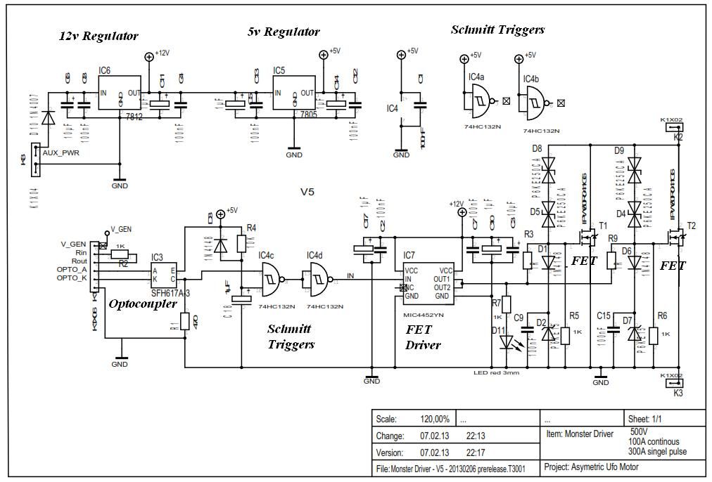
        John Stone told me that R2 should be 330 ohms Not 1K ohms as shown
        Please confirm before Production
        Kindest Regards

        Kogs Just keeping his eye on things

        Comment


        • well, I have the new drivers hooked up to motor and will try tonight after work.
          Dana, here is a vid of the new program running the drivers. Does this output look correct? Pulse within a pulse.

          Driver rebuilt and programmed with new code - YouTube

          machine

          Comment


          • Machine, that looks better...

            Originally posted by machinealive View Post
            well, I have the new drivers hooked up to motor and will try tonight after work.
            Dana, here is a vid of the new program running the drivers. Does this output look correct? Pulse within a pulse.

            Driver rebuilt and programmed with new code - YouTube

            machine
            Hey My Friend Machine!

            That looks cool man!


            Good...BUT...I would like to see the SEQUENCE at LOW Pulses...

            A SEQUENCE given by Channel 1, then 2, then 3, then 4.

            I just saw there Four LED's blinking RANDOMLY, without A PATTERN...That is seen better at Low Duty Cycle, then start increasing it.

            And please, set them IN ORDER, 1,2,3 and 4...from left to right or from right to left , whatever your preferences are....

            The "Order" of the "Sequence" is a VITAL ISSUE here to create a SOLID/ROBUST RUN on your Imperial.

            Please watch again Dana's and Hitby's videos on blinking their LED's...They are Both VERY organized.

            If you fire Channel 1 at Motor Gate 1...BUT then fire Channel 2 at Motor Gate 3...it WILL NOT have the CONTINUITY STEPS to GAIN the required FORCE/SPEED...To start from zero...or to become steadily running robust/strong.
            Plus you will put a HECK of a stress on your FET'S to "DRAG" your Imperial Heavy Rotor Mass from TOO WIDE POINTS in the Circumference. Realize you are making a contact at Gate 1 then at 3...that is exactly 180º apart...too much for that mass, as it will take too long time also.

            The closer the angles to fire them...the less stress on your Controller.

            Hope you understand my point.

            Now, I do not understand the "Pulse within a Pulse" meaning you "see" there...?

            It is NOT a Pulse within another Pulse...they are ALL separated by TIME...IF you get them mixed Up, one within others...Motor will never turn my friend.


            BEFORE YOU TEST MOTOR WITH ALL FOUR CHANNELS/GATES

            I would like you to make a simple test:

            Hook Channel 1 to Gate ONE (1)...(Just ONE MONSTER MODULE)...And start from VERY LOW DUTY/PULSES/HERTZ, dialing SLOWLY, til you start hearing the Motor Coils "Ticking"...You MUST get a running response there, once you get higher duty cycle.

            IF Motor does not turn as am writing here...don't bother going into the Full Four Gates...You must resolve first this issue with just one signal/channel/pulse...


            Regards My Friend


            Ufopolitics
            Last edited by Ufopolitics; 07-13-2013, 03:45 PM.
            Principles for the Development of a Complete Mind: Study the science of art. Study the art of science. Develop your senses- especially learn how to see. Realize that everything connects to everything else.― Leonardo da Vinci

            Comment


            • Hey UFO,
              Dana gave out a new code UFO, different from the first one. I used the one posted 2 pages ago, he also sent me one pm, not sure if same, I will check when I get home. But the scope shot shows a square wave, but each pulse is made up of pulses.
              I'm still not sure if signal is correct from arduino. Dana will have to confirm, but there is no frequency adjust. Also you can change duty of the inner pulses, but the large slow pulse, which contains the fast pulses within it, is not adjustable.
              I'm not sure if this is technically PWM. Seems more like amplitude modulation.
              I was too tired last night to check anything else. Lets see what Dana says.

              LEDs do visibly flash in sequence, but can't see it on vid. Led flashes on, and while it is on, it pulses, the duty of which can be adjusted. I was pretty tired but I'm sure that is what was happening.

              Machine
              Last edited by machinealive; 07-13-2013, 05:17 PM.

              Comment


              • Originally posted by machinealive View Post
                Hey UFO,
                Dana gave out a new code UFO, different from the first one. I used the one posted 2 pages ago, he also sent me one pm, not sure if same, I will check when I get home. But the scope shot shows a square wave, but each pulse is made up of pulses.
                I'm still not sure if signal is correct from arduino. Dana will have to confirm, but there is no frequency adjust. Also you can change duty of the inner pulses, but the large slow pulse, which contains the fast pulses within it, is not adjustable.
                I'm not sure if this is technically PWM. Seems more like amplitude modulation.
                I was too tired last night to check anything else. Lets see what Dana says.

                LEDs do visibly flash in sequence, but can't see it on vid. Led flashes on, and while it is on, it pulses, the duty of which can be adjusted. I was pretty tired but I'm sure that is what was happening.

                Machine
                Hey Machine...

                I believe it depends from where are you collecting the Signal to your Scope from the Arduino Microprocessor...

                To me it seems (according to your explanation) that you are getting in Scope all Four Signals together as One Long Pulse...

                Arduino should be able to brake it down in Four different Pins...The Problem is that I believe None of Us have a Four Channel Scope...they are too expensive man...but that would be the ideal way to "see" this.


                Let's see what Dana says about this here...


                Warm Regards


                Ufopolitics
                Principles for the Development of a Complete Mind: Study the science of art. Study the art of science. Develop your senses- especially learn how to see. Realize that everything connects to everything else.― Leonardo da Vinci

                Comment


                • Thread Quorum request for Kogs on R2 resistor value change post 2059

                  Originally posted by iankoglin View Post
                  G'day Sanpojo and especially John Stone
                  John Stone told me that R2 should be 330 ohms Not 1K ohms as shown
                  Please confirm before Production
                  Kindest Regards

                  Kogs Just keeping his eye on things
                  Hi Kogs, Dana said that he doesn't use that setup. I myself do not know what that resistor is doing stranded between 2 pins of the connector. I gather some test point hook-up consideration? Do you know exactly?


                  Too late for our first order of PCBs, but I should get a change in the gerber files made before he posts to his store. Wish me luck on that one in Target 3001. Apparently need training or hammering at it forever to make it work for me.

                  If the R2 value is not critical, should I go ahead and let OSHPark post the board using these files?
                  @Ufo, @Dana? Cornman? whomsoever? Can I get a quorum?

                  I am going to contact OSHPark about board upgrades, and how easily he may handle them...
                  Last edited by sampojo; 07-13-2013, 06:55 PM.
                  Up, Up and Away

                  Comment


                  • Originally posted by machinealive View Post
                    Hey UFO,
                    Dana gave out a new code UFO, different from the first one. I used the one posted 2 pages ago, he also sent me one pm, not sure if same, I will check when I get home. But the scope shot shows a square wave, but each pulse is made up of pulses.
                    I'm still not sure if signal is correct from arduino. Dana will have to confirm, but there is no frequency adjust. Also you can change duty of the inner pulses, but the large slow pulse, which contains the fast pulses within it, is not adjustable.
                    I'm not sure if this is technically PWM. Seems more like amplitude modulation.
                    I was too tired last night to check anything else. Lets see what Dana says.

                    LEDs do visibly flash in sequence, but can't see it on vid. Led flashes on, and while it is on, it pulses, the duty of which can be adjusted. I was pretty tired but I'm sure that is what was happening.

                    Machine
                    Wow, I didnt realize the inputs from Garry led to pulses within pulses! Or is this something new? Wouldn't the larger outside pulses be the 30hz value Dana talks about, which he has optimized for performance on his Imperial? This seems like pulse width modulation squared to me !!! The lady likes it crazy right? I would advocate for one pulse per commutator element, but that would be in the hundreds of KHz. I think I read these arduinos don't go that high somewhere on a post. Having adjustability for both duty cycles would be needed for testing to see what is best.
                    Last edited by sampojo; 07-13-2013, 06:54 PM.
                    Up, Up and Away

                    Comment


                    • [QUOTE=iankoglin;235077]
                      Originally posted by sampojo View Post
                      HI John Stone, welcome back and hope your wife is doing well.

                      I had been working on using ExpressPCB as a source of prototype boards until a member pointed out OSHPark, and I submitted your gerber files to them. ExpressPCB does not use gerber files from customers. So I had attempted to use their software to make a similar PCB to the T3001. I could not seem to crack design processes in T3001. I had been concerned about equidistance on the heavy leads and making the PCB separable between FETs and FET Drivers, As Don H and Dana seemed to like to build that board separated from the input section. You may have noticed some of those board designs I posted. Although OSHPark edges ExpressPCB out in price, its not by much and an alternate source may still be a good idea. So I hadn't posted the latest design to address the above concerns. So here it is.


                      I apologise for staying apart from this thread. Sorry!
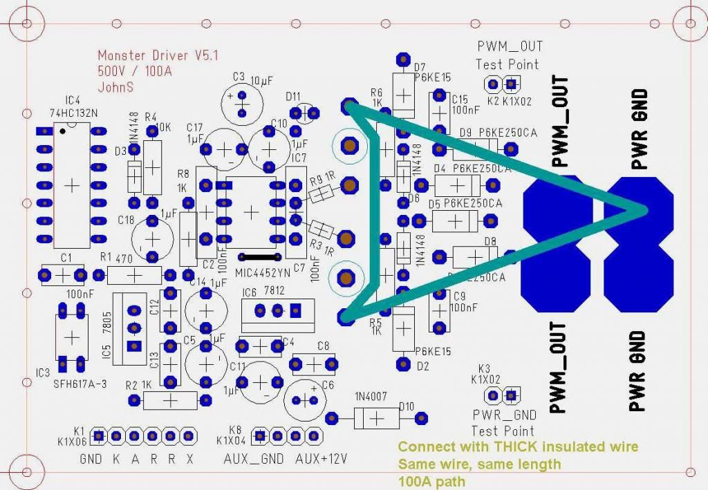
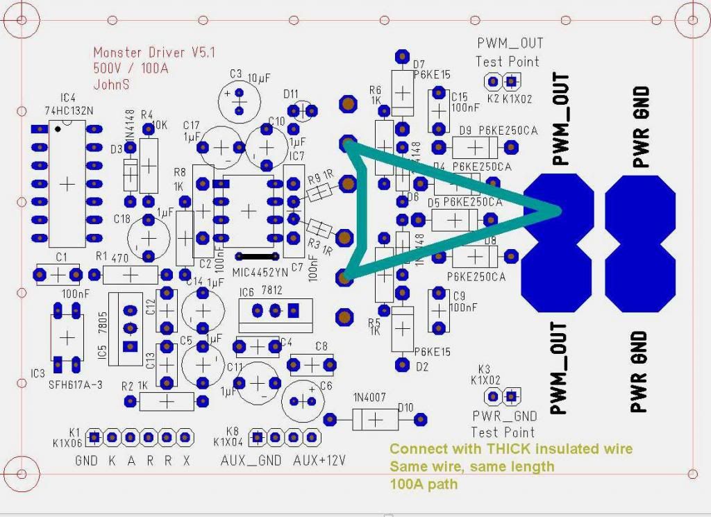
                      The PCB pic above does not follow the thorough placement I have in my layout. Blocking caps shall be as close as possible to their IC. The absolutely important area at output of driver IC shall be as short as possible - and symmetrically regarding those two FETs. Else we might get oscillations and dead FETs.
                      I strongly advise to use my layout because it was tuned in detail. I redid it three times up to the last version. Remember: we use FETs in low frequency area but want to have them switching as fast as possible in order to stir radiant and keep FETs cool. And exactly this fast switching makes the circuit RF!!!! A connection on PCB of a fraction of an inch performs like additional L, C, R (depending on frequency and length) .... Therefore they shall be short especially in the area of driver IC and gates. And any connection shall be tuned to the current flow.
                      Anybody is free to modify the layout at will. But if you are not trained in layout matters you might do wrong on seemingly very simple areas.
                      My layout was done based on 1/10" /2.54mm. It should be easy to redo it in any other drawing tool.


                      And yes R1 shall be about 330 Ohms. Some of you tried (can't remember who) 1K and the opto did not work. Sorry - my miscalculation

                      R2 is there for your convenience in order to use it either as pullup resistor or as series resistor - depending on the type of frequency source you have. You need to calculate the value for your setup.
                      At Arduino it needs to be a series resistor.


                      BTW: Can anybody repost the link to the current Arduino program. I am going to dig into Arduino looking forward to next tasks (and learning C as well!!!)
                      JS
                      Last edited by JohnStone; 07-13-2013, 08:21 PM.
                      Experts spend hours a day in order to question their doing while others stopped thinking feeling they were professionals.

                      Comment


                      • Originally posted by machinealive View Post
                        Hey UFO,
                        Dana gave out a new code UFO, different from the first one. I used the one posted 2 pages ago, he also sent me one pm, not sure if same, I will check when I get home. But the scope shot shows a square wave, but each pulse is made up of pulses.
                        I'm still not sure if signal is correct from arduino. Dana will have to confirm, but there is no frequency adjust. Also you can change duty of the inner pulses, but the large slow pulse, which contains the fast pulses within it, is not adjustable.
                        I'm not sure if this is technically PWM. Seems more like amplitude modulation.
                        I was too tired last night to check anything else. Lets see what Dana says.

                        LEDs do visibly flash in sequence, but can't see it on vid. Led flashes on, and while it is on, it pulses, the duty of which can be adjusted. I was pretty tired but I'm sure that is what was happening.

                        Machine
                        confused
                        If I understand you right: what we call one single pulse is composed at your setup of a packet of n pulses. The duty cycle of these sub pulses is variable.
                        Right? If yes this is definitely NOT what UFO talks of. And additionaly it might be a FET killer.

                        I'll tell you what I understood we require to have:
                        1st channel emits a SINGLE pulse first (i.e. 1ms) and waits another 3 ms before repetition (5ms for MAG3) in order to allow the other 3 channels (5 fro MAG3) to perform their 1ms pulse each. In this case any channel repeats its pulse 250 times a second (166.6 times for MAG3). UFO showed exactly this in his diagram.
                        Overall: any channel is allowed to perform maximum 25% duty cycle in order to not overlap with other channels (16.6% for MAG3). But this duty cycle can be reduced down to 1% i.e. leaving a dead zone in the range of its time slot (24% / 15.6%). Duty below 1% does not make any sense and should be omitted.

                        Last two days I dug into Arduino. My notion: Any predefined library like Ardunio PWM or other commands do their job fine in the range of their dedication but not for our pulse scenario being very special.
                        Now I have a basic proggy covering a very huge range of frequencies along minute processor load. It can be scaled on the fly from 1 channel up to 8 channels with very same processor load and precision in µs range.
                        Unfortunately I am slow in programming and it will take some time for further addons (expecially control of frequency and duty).
                        Summing up: Arduino is a smart guy but it needs to be treated gently in order to get it running as a champion.

                        I am eager to examine the current program as soon I get a link of it.

                        JS
                        Last edited by JohnStone; 07-13-2013, 08:19 PM.
                        Experts spend hours a day in order to question their doing while others stopped thinking feeling they were professionals.

                        Comment


                        • pwm new program

                          @Dana
                          Thanks for trying the code that I posted. As I see it, and I may be wrong, we have two values that we can control here. 1.) the duty cycle and 2.) the wait period. Initially the wait period will have multiple pulses depending on how long the wait period is. Each pulse will be 2 ms long and divided into an increment of that 2ms period ie if the duty cycle is 255 then it will have full duty cycle for that entire wait period for that pin. if that wait period is 16 milliseconds long and the duty cycle is 64 there will be 8 pulses and each pulse will be .5 milliseconds long. I believe that this is exactly what is necessary to get the overall wattage down. I may be wrong and we have not really tried it much on any setup. There is no overlap between pins with this scheme. So there should be no fighting within the machine over the energized fields. The waves are perfect squares and switch on and off extremely quickly and I think will run cooler than the other method which is basically 100% on divided by four periods each a quarter duty cycle.
                          @John Stone
                          You may be correct in that this method may be an fet killer. I only wish that I were at the point of building the imperial to test it out. I unfortunately came into the thread in January and have only had time to build the goldmine replications and am presently building the goldmine generator which is still a proof of concept for me. The reason that I brought this to the forum was that I thought it would give better control to consumption of energy. And from the point of view of electric generation it would make automatic motor control easier to implement. Now we have two variables that can be controlled programmatically. I am working on code to demonstrate this capability and will post it tomorrow. I think you will like it. Let's not be hasty in denouncing something because it is different. This is research and development in its purest sense. If it doesn't perform as I expect it will then I will be the first to admit the error. I do think that using a potentiometer for the wait period and having the duty cycle set to 1/4 is the best solution for a scooter, motorcycle, or even a small car where you simply tie the pot into a cable similar in function to a accelerator pedal.
                          I do know that Tesla thought fast abrupt breaks were the best means of getting cold electricity to get excited. This may come at a cost to fets I would hope not for isn't that what we want with this technology, a way to draw the lady out so that she will do useful work on the behalf of all.

                          cheers

                          garry

                          Comment


                          • copper sheeting

                            Greetings all:

                            I have contacted Ms. Betty and hope to have several very nice FETs in a few days. Thanks to Kogs for the repost on that address, and to the original finder.

                            It will be interesting to see how they perform on the various coils sitting in my basement.

                            I purchased for parts, a large UPS system which was loaded with inductor coils, caps, and a couple of transformers. The winding on the inductor coils is copper sheet. The copper is about 4 inches wide and might be useful for reinforcing the current carrying traces on the JS FET Driver Boards that some are making.

                            The sheet can be trimmed to cover the trace and soldered into place. Or, double it up and solder down.

                            Anyway, 'tis free for the asking unless mailing gets crazy. Then, I would only ask to be reimbursed for the postage after you receive the package.

                            Contact me via PM and we'll work out the details.

                            glen

                            Comment


                            • Yes , Correct.

                              Originally posted by JohnStone View Post
                              confused
                              If I understand you right: what we call one single pulse is composed at your setup of a packet of n pulses. The duty cycle of these sub pulses is variable.
                              Right? If yes this is definitely NOT what UFO talks of. And additionally it might be a FET killer.
                              Hello John,

                              Yes , You understood perfectly well, and as a matter of fact, thanks to your observation, I see now what Machine was showing at Scope.

                              And, Yes, that was NOT the Design I was originally proposing to drive Imperial.

                              If it could be a "FET Killer"...then Machine Alive, you do NOT need this...unless you have developed a "FET'S Serial Killer Syndrome"...LOL...


                              I'll tell you what I understood we require to have:
                              1st channel emits a SINGLE pulse first (i.e. 1ms) and waits another 3 ms before repetition (5ms for MAG3) in order to allow the other 3 channels (5 fro MAG3) to perform their 1ms pulse each. In this case any channel repeats its pulse 250 times a second (166.6 times for MAG3). UFO showed exactly this in his diagram.
                              Overall: any channel is allowed to perform maximum 25% duty cycle in order to not overlap with other channels (16.6% for MAG3). But this duty cycle can be reduced down to 1% i.e. leaving a dead zone in the range of its time slot (24% / 15.6%). Duty below 1% does not make any sense and should be omitted.

                              JS
                              Yes, that is the way...Dana has already run Imperial smoothly with this set up...however, I see some of the "limitations" as duty cycle concerns...and no option to variate the "Off Times" between Channels...

                              That is why Garry offered his design...there is only one Main Problem with this, besides the ones cited above...

                              @Garry (GChilders): Your idea is very "interesting" and I think we should keep it in mind as it may be usable on other arrangements...and/or correcting/improve, some design issues with the wave pattern.
                              The problem I see: (and I have to admit I do not have full understanding yet of this wave design, so, please, let me know if I show ignorance about it at any point)

                              Asymmetrical Motors require that the "Energizing Milli Second Time" per Pair or Coils, meaning, per Interaction when Brush hit their commutator elements...be done at a Steady Rate, in order that coil could develop in the shortest time possible, enough magnetic field strength that would allow to generate the required speed/torque...

                              If We look at this Coil Feeding till it develops a full Magnetic Field Strength...it is an "Ascending Mode Curve" through Time...and NOT a Flat Line...parallel to time.

                              And as I can see in your design...you are fractionating that already small timing On, for Pairs-Coils, into "Mini Pulses"...This will end up weakening the required strong magnetic field development within the On Time....The responsible Parameter that creates Speed and Torque at same levels...I call it "Throw Out Forces"...those forces are based on "As Similar As Possible", Magnetic Field Strength between Rotor Coils at Interaction and Stators.


                              I still like Your design(I see it "pretty darn" interesting, and very different!)...and I am sure we could modify it or arrange it differently, in order that would be very functional and successful to our future development. As I agree with you if we get this to function properly it will definitively be an Ultra Low Wattage consumption for our Machines.


                              On the other hand, a FET Killer, I understand it, as it "amplifies" the amount of opened off times/gates for spikes(Our Lady) to reverse back to our "Switchers" Drains...


                              Warm Regards Sir John Stone, Garry, Machine and All


                              Ufopolitics
                              Last edited by Ufopolitics; 07-13-2013, 10:19 PM.
                              Principles for the Development of a Complete Mind: Study the science of art. Study the art of science. Develop your senses- especially learn how to see. Realize that everything connects to everything else.― Leonardo da Vinci

                              Comment


                              • I have a feeling Dana has already used this code, and it works, just a hunch. I'll still wait to make sure.

                                Comment

                                Working...
                                X