Announcement

Collapse
No announcement yet.

My Motors got me to Tap into Radiant Energy

Collapse
X
 
  • Filter
  • Time
  • Show
Clear All
new posts

  • pulse width or freq lure the witch?

    Originally posted by Ufopolitics View Post
    .... could cause it to jump without starting at zero slowly up...and that is very important to be done, cause the RE starts to develop at very low Hz...like 6-9 Hz
    The POT is very sensitive tuning...must go very slowly, and I installed a Vernier Dial to make it even slower and more precise.

    Ufopolitics
    Originally posted by Ufopolitics View Post
    This 555 oscillator regulates the Duty Cycle, not Frequency.

    Oscillator must be attached to a Coil, with the spec's I have provided, I believe it was over 1.0 Ohm, 18 awg, and around 200 turns on a 2.5 inch hollow plastic tube would do...in order to generate Magnetic Field Pulses...and the reversed Fields, at Off Times are collected through Two Ultra-fast Diodes to the CFL...
    Ufopolitics
    Originally posted by Ufopolitics View Post
    I used six Mosfets, because I also use that circuit as a controller for Motors, NOW, You guys, really, in order to drive just one Coil, do NOT need that set-up, maybe 3-4 is just fine...
    And actually that circuit IS NOT MY original concept, I got it from Gary at CHEMELEC (A great guy in case you need to order parts or already made boards, he is got very interesting projects, etc)

    Here is the link to this particular project where He explains in detail..
    A Pulse Width Modulation Control
    .....
    .....
    And Yes, You could use A different circuit, However, I do not recommend to go and buy ANY ready to turn on Controllers or Oscillators...because simply...do not work....the existing PWM Motor Controllers are designed to Rush In and start at 900Hz to 1000Hz...NOT GOOD!


    Ok the main specifications on Wave is to be ASTABLE ...
    The second and to me the Main ONE, Is that it starts from ZERO, ONE, TWO...SO ON HERTZ PULSES..
    Ufopolitics
    Thank you for you time, UFOPolitics!
    Hope i do not irritate you too much, but i am confused,
    does this circuit with pulswidth lure REwitch, and with exactly this you light a bulb in a water, or i need another one,not mentioned in this thread, that doing change freq from very low hz?may be low hz means low hz on the cold side while on the hot side is fixed ~500Hz and slowly change from 50%dutypositive down to ~10%...
    on one hand you recomend to use this circuit(if i understand right) and to change freq from low hz, on another hand you agree that this one regulates the Duty Cycle, not Frequency.
    i understand about attached coil, but not quite understand where to attach: to pulse width modulator or freq modulator.
    If my question looks strange, do not care, may be i did not understand enough and only spend your time;
    i am very impressed of all you are disclose here and do not want to annoy you.
    Regards sawa.
    Last edited by sawa25; 03-22-2014, 10:58 AM.

    Comment


    • Bonjour OVNI

      I found a few pictures on my cell phone while I was making the rotor. I can upload them here, but it says my limit of 3.4 megs is full and I cant seem to delete old pictures...

      Joel

      Comment


      • Hello UFO,
        I am trying to upload picture, but the server is not allowing me cause apparently I have attained my 4 meg maximum. I cannot seem to delete old pictures. <can you help me out on putting my pictures ??

        Joel

        Comment


        • Photobucket...

          Originally posted by lerameur View Post
          Hello UFO,
          I am trying to upload picture, but the server is not allowing me cause apparently I have attained my 4 meg maximum. I cannot seem to delete old pictures. <can you help me out on putting my pictures ??

          Joel
          Hello Lerameur,

          You need to create a Free Account at Photo and image hosting, free photo galleries, photo editing

          Go to Sign Up and fill your info.

          You will have plenty of room to upload pictures there, then post links here.

          Handling Images is very easy, just copy IMG link on your right hand side bar at Photobucket, then paste link here on above editor Insert Image small window...preview post before submitting replay.

          Any questions let me know

          Regards


          Ufopolitics
          Principles for the Development of a Complete Mind: Study the science of art. Study the art of science. Develop your senses- especially learn how to see. Realize that everything connects to everything else.― Leonardo da Vinci

          Comment


          • Originally posted by sawa25 View Post
            Not only in Russian but also in English, Spanish and Polish!
            ekalk

            Comment


            • Originally posted by ekalkeu View Post
              Not only in Russian but also in English, Spanish and Polish!
              ekalk
              You are correct about it ,
              but the main question is freq or pulse chg to start RE.
              Now on circuit with coil and load(KOm or CFL) i only see with scope, (connected to G of mosfet) - mutilated meander -with very high very short pulses on the moments of switch OFF the mosfets; it seems RE draw back to circuit instead of going through diodes to load.
              on the same time the another Scopeprobe, connected to load(w/o ground) - repeate the form of input pulses in general.
              i thought - it should be opposite to input because of diodes.
              Last edited by sawa25; 03-24-2014, 03:19 PM.

              Comment


              • Originally posted by sawa25 View Post
                You are correct about it ,
                but the main question is freq or pulse chg to start RE.
                Now on circuit with coil and load(KOm or CFL) i only see with scope, (connected to G of mosfet) - mutilated meander -with very high very short pulses on the moments of switch OFF the mosfets; it seems RE draw back to circuit instead of going through diodes to load.
                on the same time the another Scopeprobe, connected to load(w/o ground) - repeate the form of input pulses in general.
                i thought - it should be opposite to input because of diodes.
                Hello Sawa,

                This circuit is a PWM Controller, as almost every controller out there for regular motors are Pulse Width Modulators.

                If you read Gary's original circuit designer...He tells that Duty Cycle is what is changed here.

                The reason of confusion raised when we used Digital Multi Meters that read Frequency and added to Input and Output...then we got Hertz readings...If You do that, you will also get the two different Pulses from Input and Output on DMM...where Output is greater than Input.

                Regards


                Ufopolitics
                Principles for the Development of a Complete Mind: Study the science of art. Study the art of science. Develop your senses- especially learn how to see. Realize that everything connects to everything else.― Leonardo da Vinci

                Comment


                • Originally posted by Ufopolitics View Post
                  The reason of confusion raised when we used Digital Multi Meters that read Frequency and added to Input and Output...then we got Hertz readings...
                  Ufopolitics
                  Hello, UFOPolitics,
                  O, very thank for crarification.
                  i missed that.
                  i use oscilloscope for everything in this finding.
                  So i keep going to tune with pulsewidth.
                  Also to be sure about CW/CWW/N/S:
                  all we know the most popular screw thread named right thread (used almost everywhere,against left thread, used sometimes
                  in places, where right thread can unscrew by itself (left bycicle pedal))
                  so if our coil looks like right thread, then where to put +, there will be the North, right?
                  Regards sawa.
                  Last edited by sawa25; 03-24-2014, 04:17 PM.

                  Comment


                  • Originally posted by sawa25 View Post
                    Hello, UFOPolitics,
                    O, very thank for crarification.
                    i missed that.
                    i use oscilloscope for everything in this finding.
                    So i keep going to tune with pulsewidth.
                    Also to be sure about CW/CWW/N/S:
                    all we know the most popular screw thread named right thread (used almost everywhere,against left thread, used sometimes
                    in places, where right thread can unscrew by itself (left bycicle pedal))
                    so if our coil looks like right thread, then where to put +, there will be the North, right?
                    Regards sawa.
                    Hello Sawa,

                    For windings of Coils I use "My Right Hand Rule"...

                    [IMG][/IMG]

                    Just look at Left side coil and hand, notice Top wire goes to the Positive (+) Commutator on top, so Positive "signal" runs toward my fingers tips, then my Thumb aims to North Pole.

                    That gives you the way to hook up/wind your static coil.

                    By the way, remember that if you use bifilar wire (dual strands) of like 18 awg (American Wire Gauging) and keep above One Ohm (I rather stay at 2.0 Ohms) you will get better results.

                    If you are using a solid steel core for coil...then test by holding a CFL (or could be a Neon Bulb) with your hands, touching only the screwing side...then touch the steel core with the other end tip...and watch it while you put up/dial up pulses...

                    Take care


                    Ufopolitics
                    Last edited by Ufopolitics; 03-24-2014, 04:37 PM.
                    Principles for the Development of a Complete Mind: Study the science of art. Study the art of science. Develop your senses- especially learn how to see. Realize that everything connects to everything else.― Leonardo da Vinci

                    Comment


                    • Hello, friend UFOPolitics.
                      Thanks, you was so kind, that repeat the pics and explanations, that you
                      already posts for all of us and i already saw this version also,
                      i was asking again, because i really dumb and goofy to understand sometimes not native language,
                      and i trying formulated as simple and uniquely, that i can grasp.
                      Sorry.
                      thats why i again not sure, and outline the wire on your pic,
                      that i think lay on top,
                      ami right?

                      sawa
                      Attached Files
                      Last edited by sawa25; 03-24-2014, 06:17 PM.

                      Comment


                      • Originally posted by sawa25 View Post
                        Hello, friend UFOPolitics.
                        Thanks, you was so kind, that repeat the pics and explanations, that you
                        already posts for all of us and i already saw this version also,
                        i was asking again, because i really dumb and goofy to understand sometimes not native language,
                        and i trying formulated as simple and uniquely, that i can grasp.
                        Sorry.
                        thats why i again not sure, and outline the wire on your pic,
                        that i think lay on top,
                        ami right?

                        sawa
                        Yes, that is right, Sawa
                        Principles for the Development of a Complete Mind: Study the science of art. Study the art of science. Develop your senses- especially learn how to see. Realize that everything connects to everything else.― Leonardo da Vinci

                        Comment


                        • Originally posted by iankoglin View Post
                          G'day Midaz
                          To use the JS Monster you need 2 other Items
                          You need a drop down 40v down to 12v power Regulator I purchased one on EBay but it seems they are not there any more

                          Also you need a 5k pot oscillator that is set to give output duty cycle 0 to 100%

                          On the Oscillator you should have 6 connections
                          1=Pot low, 1=Pot wiper , 1=pot high
                          1=the 12v+, 1=Negative, and 1=Oscillator output

                          Now the Pot is replaced by the Magura twist hand throttle as it is really a 5k potentiometer
                          the connections are the:-

                          Blue wire goes to the high side of the pot
                          Brown goes to the wiper
                          Black goes to the low side of the pot

                          You set the low and high by testing the output from the oscillator with A DMM set to more than Duty cycle
                          Then place the Black probe to the negative Common and the red probe to the output of the Oscillator the Magura is set that when it is at rest the duty cycle should be 0%) and when you twist it the Duty cycle increases till it reaches 100%(mine only goes 0 to 99%)
                          If the Magura is reversed that is at rest it reads 100% then just exchange the Blue and the Black wires

                          The Monster that Dana has built is really a 4 times JS Monster that I believe has one input from the Oscillator But you will have to ask Dana where the connections go and what the voltages are as I think from memory that he upped the voltage to the driver as he was using only one auxiliary input higher than 12v so as to cater for the voltage drop over the 4 Monsters

                          If you can not find one There is a few on the forum


                          I hope this helps
                          Kindest Regards
                          Kogs]
                          G'day Midaz
                          DiD you get a 5 k oscillator to use with the Megura throttle so you can connect to the JS Monster driver IT must be one that uses a 5K ohm input

                          I finally found some 40v regulator here on EBay

                          DC DC Buck Step Down Converter Module LM2596 Voltage Regulator LED Voltmeter M3 | eBay

                          Kindest Regards

                          Kogs keeping his eye on the job

                          Comment


                          • Originally posted by iankoglin View Post
                            G'day Midaz
                            DiD you get a 5 k oscillator to use with the Megura throttle so you can connect to the JS Monster driver IT must be one that uses a 5K ohm input

                            I finally found some 40v regulator here on EBay

                            DC DC Buck Step Down Converter Module LM2596 Voltage Regulator LED Voltmeter M3 | eBay

                            Kindest Regards

                            Kogs keeping his eye on the job
                            Kogs,

                            Thank you for finding parts for me. I appreciate your help. Is that all I need to connect my throttle?

                            Keep it Clean and Gren
                            Midaz

                            Comment


                            • Bonjour UFO,

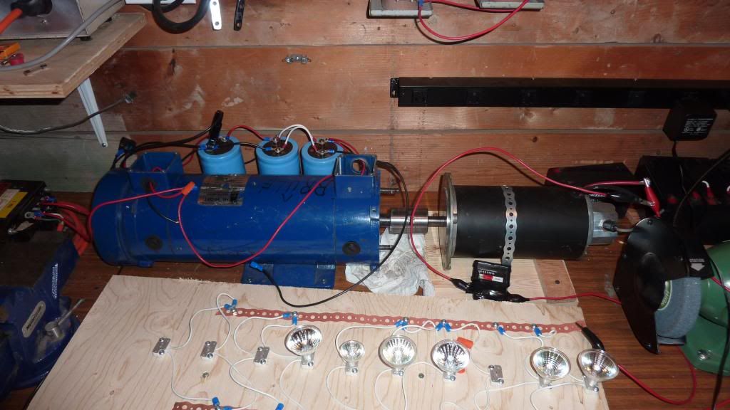
                              Bon, here are a few pictures of my motor,It is a 2 stator motor using the John Stone circuit. I dont see why I cannot use it on this motor or need two. I hook it up like you showed. Meaning: Battery--motor Input- motor output --Circuit ---ground. ( ground is same as battery ground)
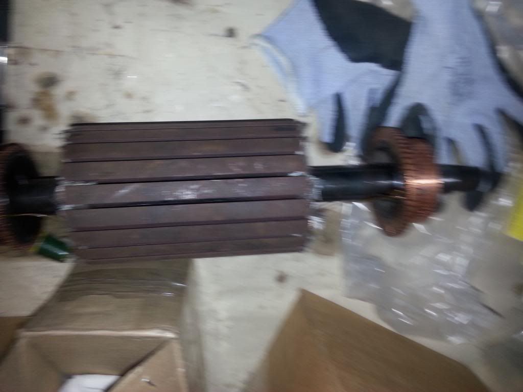
                              Rotor:

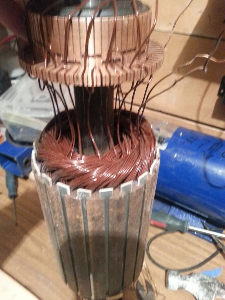
                              Coiled rotor:

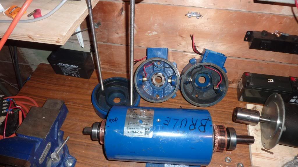
                              Motor parts:


                              Full setup with dc motor as a load on the right:


                              I'LL be making a video soon. BUt like I said I am getting some mixed results.
                              When I use full duty cycle I get the most RPM as I decrease the duty cycle like you said, I get less rpm and less output power on the DC motor. I am not seeing the radiant helping in turning the motor... Maybe I am not using the right glasses LOL

                              Joel

                              Comment


                              • Basically, this is my setup:


                                with the pulsar at the lower left.

                                Joel

                                Comment

                                Working...
                                X