Announcement

Collapse
No announcement yet.

My Motors got me to Tap into Radiant Energy

Collapse
X
 
  • Filter
  • Time
  • Show
Clear All
new posts

  • Try this one...

    Originally posted by lerameur View Post
    Basically, this is my setup:


    with the pulsar at the lower left.

    Joel
    Comme ces't va Monsieur Lerameur?

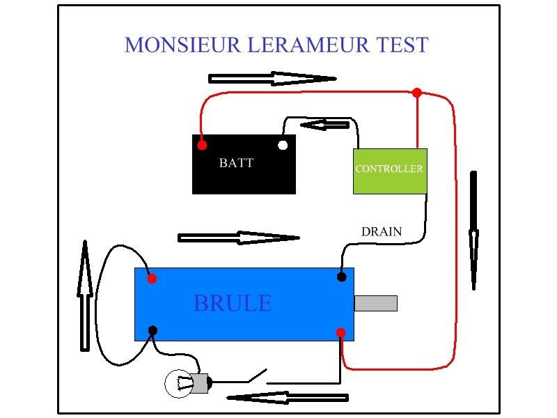
    Please try this test:

    [IMG][/IMG]

    Get the Oscillator or Controller to run motor at a pretty nice speed, not too much though...say a medium speed...then turn on the switch to light bulb ...

    This is assuming you are using 12V Batteries...and the Bulb is a Car/Vehicle Incandescent type...12 Volts also...

    I set a positive to controller, assuming you are feeding it from your batteries...but the main thing here are the Motor connections.

    Watch/Record Motor Speed BEFORE and AFTER turning switch OFF/ON...with a Tachometer test would be much better...


    Please, let Us know what happened...


    Regards


    Ufopolitics
    Last edited by Ufopolitics; 03-30-2014, 03:22 AM.
    Principles for the Development of a Complete Mind: Study the science of art. Study the art of science. Develop your senses- especially learn how to see. Realize that everything connects to everything else.― Leonardo da Vinci

    Comment


    • Originally posted by Ufopolitics View Post
      Comme ces't va Monsieur Lerameur?

      Please try this test:

      [IMG][/IMG]

      Get the Oscillator or Controller to run motor at a pretty nice speed, not too much though...say a medium speed...then turn on the switch to light bulb ...

      This is assuming you are using 12V Batteries...and the Bulb is a Car/Vehicle Incandescent type...12 Volts also...

      I set a positive to controller, assuming you are feeding it from your batteries...but the main thing here are the Motor connections.

      Watch/Record Motor Speed BEFORE and AFTER turning switch OFF/ON...with a Tachometer test would be much better...


      Please, let Us know what happened...

      Regards

      Ufopolitics
      G'day UFO
      In place of the light bulb or Neon If I connect say 2 diodes and connect to a Capacitor in parallel with the batteries should I be able to charge the batteries at the same time

      Kindest Regards

      Kogs in thinking mode

      Comment


      • Charging Batteries...

        Originally posted by iankoglin View Post
        G'day UFO
        In place of the light bulb or Neon If I connect say 2 diodes and connect to a Capacitor in parallel with the batteries should I be able to charge the batteries at the same time

        Kindest Regards

        Kogs in thinking mode


        Hello Kogs,

        Yes you will charge batteries, however, the Voltage measurement between those two points where Bulb is connected, will deliver somewhere around HALF of the total Input from Batteries...

        I have shown you better ways to charge batteries in my other Diagrams to Nessie...

        I am trying for Lerameur to observe "something else" here...


        Regards


        Ufopolitics
        Principles for the Development of a Complete Mind: Study the science of art. Study the art of science. Develop your senses- especially learn how to see. Realize that everything connects to everything else.― Leonardo da Vinci

        Comment


        • Hello UFO,

          The way i see , I cannot get that motor running without the switch being on (switch closed):
          I took your diagram and added the current path:

          As you can see it goes through the switch.
          I am going to try it anyhow

          Joel

          Comment


          • Originally posted by lerameur View Post
            Hello UFO,

            The way i see , I cannot get that motor running without the switch being on (switch closed):
            Hello Monsieur Lerameur,

            OUI Messie...Motor WILL RUN with switch open...

            What about the Motor Inner Coils you wound on the BRULE Machine...What happen you forgot about them?...

            They will conduct current, Mon Ami...pulsed while rotation occurs but will run motor steadily and with lower Amps Draw...for sure...and will light Bulb as well when Motor is running...and switch on.

            I took your diagram and added the current path:

            As you can see it goes through the switch.
            I am going to try it anyhow

            Joel
            One thing is Reality...and another One is Theory...Mon Ami...

            [IMG][/IMG]

            Please let Us know when you run it (with switch off)...then ON.


            Au Revoir


            Ufopolitique...(avec L'Francoise)
            Principles for the Development of a Complete Mind: Study the science of art. Study the art of science. Develop your senses- especially learn how to see. Realize that everything connects to everything else.― Leonardo da Vinci

            Comment


            • Re bonjour.

              I am having difficulties with the circuit...
              My P6KE250CA diodes are heating tremendously (énormément).. even burnt.. I need to order new diodes. even had one of the mosfet burnt !!
              I am using 48v and its taking 15A to 12A. maybe its too much.. i did installed heatsink on these mosfet.
              I will for the new parts to come in before trying it again.

              Joel

              Comment


              • circuit for Leremeur

                @ufoPolitics

                I tried this circuit on my 4 rotor gold mine motor and was a little surprised at the results. I ran it with 12 volts as recommended. The motor slowed very little when the light was switched on, about 50 rpms were lost. This was surprising because when I tried to run the halogen headlamp at 24 volts with the light connected to the generator circuit I had a very difficult time maintaining rpms. The rpms were significantly higher with 24 volts, about 3500 as opposed to around 1500 with 12 volts, but the rpms were cut in half, when hooking the light up to the generator circuit. In both cases I experienced no overheating. The light would not get as bright as I felt it should when I ran 24 volts. The light lit up very bright with the 12 volt set up. I am very busy right now with installations and haven't had the time to video all of the tests that I am running. Hopefully by next week end I can post some videos.

                Cheers,

                Garry

                Comment


                • Where do you, RE?

                  Hello, UFOPolitics,
                  I hope any of your comment if possible:
                  it seems, that i have usual hot current on cold side.
                  I made coil 1mm wire on 5cm paper tube, 1.6 Om.
                  3 layer 120+120+110turn(wrong calc the total length)
                  (I guess it is quite same as was your coil.)
                  six mosfets are 2sk2837 toshiba
                  mosfets are always cold.
                  (what i do not like in 2sk2837, compare // to your nte2397 is
                  turn-on delay 70 // 14
                  rise time 30 // 27
                  turn-off 290 // 50
                  fall time 50 //24)
                  diodes two HFA16PB and two 1n4148 for the cold side, connected accordingly your recomendations.
                  the pot now is 250KOM (same as your)

                  on the cold side i connect in parallel:
                  resistor 110 Om 15W
                  CFL bulb 7W 240V
                  CFL bulb 23W 240V
                  usual bulb 95W 240V

                  the bulbs became full light(except usual bulb - it light lower then half) in almost all range of rotation of pot 250KOm
                  without or with slow tuning - no matter.
                  coil and resistor and bulbs became hot very quickly - 15 seconds

                  if i swap coil ends, nothing changes -
                  quite the same behavior.

                  going to try IRF740 instead 2sk2837
                  Last edited by sawa25; 04-03-2014, 07:16 AM.

                  Comment


                  • digital-isolator vs opto-isolator

                    Originally posted by JohnStone View Post
                    OK Cornboy, you got your PSU running. Sorry for that forgotten wire jumper . But you took the chance to learn how a voltage regulator behaves if its GND pin is floating. You never will forget it !

                    Today you will assemble section C with opto.

                    First of all I apologize for some errors.
                    • Resistor R1 has proved to be 330Ohm
                    • At opto pin naming C and E are reversed in circuit diagram but pinning is connected OK and PCB is OK - no modification required.
                    • Those two wire jumpers are a mystery to me. It is copper below -> ignore them.


                    BTW: After you have your monsters running I will add this tutorials and corrections to my 5.1 document and will issue a final version V6.0.


                    OK hands on now:
                    1.
                    Before you assemble the section C we need to discuss what gen output you intend to use. For 5V R2 shall be 330Ohm (Arduino). The value of 1K was dedicated for 15 volt outputs like from NE555 timer driver.
                    Arduino outputs source current in high state and sink current in low state. Similar with lab generators at TTL output. But lab generators might not be able to source 10mA for opto.
                    If you use a normal generator output please make shure to be 50 Ohm output (and not 600Ohm) and adjust output voltage to oscillate between 0V and 5V (check with scope) Adjust frequency for about 1 Hz.

                    2.
                    Assemble section C
                    You might want to use an IC socket for opto - just at this first board (easy to preplace in case of damage). You need to cut those few pins out of a normal IC socket you have available.
                    You shall assemble IC socket for IC 4 but you shall not populate it just now. It will be more easy to measure at those unpopulated socket pins.

                    3.
                    Please regard that your generator owns a private GND. You need to change ground lead of your meter if you measure at generator side. Do not forget to restore GND if you contunue checkign your circuit.

                    In order to test your generator signal signal connect:
                    • Gen output (or Arduino) to K1 pin 5 (signal Rin)
                    • Gen GND to K1 pin 2 (YES pin two!!!!)
                      ATTENTION: I insist in pin 2 and NOT pin 1. We are not allowed to connect Arduino to GND of monster driver.

                    Get an LED and connect its pins to K1 pin 4 and K1 pin 2. The LED shall be pulsating. If not reverse pins of LED. If still not get another being OK.
                    Disconnect test LED

                    3.
                    Connect K1 pin pair 3,4. Usually you solder a bubble between pins at bottom side for stable connection.

                    4.
                    Connect power to your monster board. Check 5V to be present at regulator output and opto IC3 pin4.

                    5.
                    I assume your generator (Arduino) is still connected with pulsing signal.
                    Check K1 pin 5 for pulsing signal (5V, 0V ......)
                    Check K1 pin 3 and 4 for same pulsing signal but now 1.6V ...0V .....

                    Explanation of opto function:
                    The opto input is a simple LED (IC3 pin 1,2). If you operate it without resistor in series it will die like a normal LED.
                    This LED emits light inside the sealed housing of IC3. At pins 3,4 there is connected a simple transistor. And now I explain the opto trick! This transitor has no base leg and under normal condition it would be not possible to control it. But the base of this transistor is uncovered and receives photons (light particles) from built in LED. The energy of these photons performs the miracle that our transitor decides to perform its switching function.


                    For more details see.

                    Imagine this transitor to be a simple switch. This switch is being toggled by "magic" synchronously with generator signal. What do you expect at IC3 pin 3 to happen? You switch 5V to a resistor ON / OFF / ON ....
                    • Check pin 4 to be stable 5V
                    • Check it at pin 3 to have pulses.
                    • Check IC4 pin 9 to have same signal
                    • Get your test LED and connect it to IC3 pin3,4. If it does not pulse reverse pins. LED will go OFF if opto being active (it short circuits test LED)


                    OK: That's it!
                    Next time we will discover the mystery of IC 4
                    JS
                    Hello to all.
                    Sir JohnStone and anybody, who knows,
                    is it possible to use this devices:
                    ISO7220M, http://www.mouser.com/ds/2/405/slls755l-127961.pdf
                    ADuM5240,http://lib.chipdip.ru/307/DOC000307226.pdf
                    as a gate feeding for mosfets
                    instead of usual opto,
                    because of their switching speed is nanoseconds(ISO7220M) compare to milliseconds(PVT312 for example)?
                    Regards,sawa.
                    Last edited by sawa25; 04-07-2014, 03:52 AM.

                    Comment


                    • opto isolator

                      @ Sawa25

                      You can try any thing you wish to try. You are mistaken about the speed of the opto isolator that John Stone recommends. The speed of these isolators is in micro seconds not milliseconds. A microsecond is 1/1000 of a millisecond and this is more than adequate speed for the monster drive, pulser combo to send a signal to a motor which needs the signal in milliseconds. Looking at the info sheet for the opto isolator. Turn on time is 3 microseconds, rise time is 2 microseconds, turn off time is 2.3 microseconds, and fall time is 2 microseconds. Cut off frequency is 250 kilohertz. I have not seen any thing approaching this speed with the motors we are using.

                      Cheers

                      Garry

                      Comment


                      • Kogs wants to keep it simple

                        Originally Posted by GChilders View Post

                        @Kogs

                        I have been using JS Monster Drive with the Arduino and a 5K potentiometer to change the duty cycle and it works perfectly well. I thought you had an Arduino. If you wish I can post a program for the Arduino that has a simplified format that would just be to drive a motor. All I would need from you is a target maximum RPMs to calculate the target motor frequency for the motor you are going to use as well as the number of poles and pairs of brushes. Could solve the problem more quickly.

                        Cheers
                        Garry
                        ----------------------------------------------------------------------------------------------------------------------------
                        G'day Garry
                        I thank you for your fast response
                        I have a UNO Arduino of which I do not know how to connect I appreciate any help I can get.

                        The Motors I used are 2 Chinese 1000w 20 poles and 4 magnets and 4 brushes the speed was 3000

                        Of course I have modded these motors to one motor 4 magnet Stators and 4 sets/Pairs of brushes the speed is still about 3000RPM But Now the watts is less than 200w @24V
                        I do appreciate Your help here

                        Kindest Regards

                        Kogs appreciates any help

                        -----------------------------------------------------------------------------------------------------------------------------------

                        Originally Posted by GChilders View Post @ My Asymmetric Electrodynamic Machines

                        @Kogs

                        How many monster drivers will you be using? 4? And are you going to attempt to turn each on and off with a switch as ufo has suggested? I will wait for your answer before I rewrite the program. If so the switches need to be wired to the Arduino so that they along with the throttle come into the A0 - A4 inputs. Then as they are switched on and off the Arduino will pick up the signal and start pulsing that monster drive. Let the Arduino take care of the details. You will need to make a bus for the Arduino to connect to the legs on the switches and the throttle that are not connected to A0-A4. The way the Arduino connects to the monster drives is very simple. Choose which of the outputs you want to use for each monster drive(this should be related to your firing order for your motor). This will be connected to pin 5 of K1 on the monster driver that you are connecting to that set of brushes on your motor. pin 2 will come to the ground bus for the Arduino as will all of the monster drives pin 2 on K1. Choose the next output pin that you want to use for the next monster and connect it to pin 5 at K1 and so on until your monster drives are connected. Then send me the pin numbers in the order that you have selected to fire them, along with the info about your switches. BTW I would only use the pins that have the ~ symbol next to them for they are used for the pwm method in the Arduino. Also keep pin 0 and 1 free for they are used for the interrupts.

                        Cheers,

                        Garry[Quote]
                        ------------------------------------------------------------------------------------
                        G'day Garry

                        I don't want to mess you around BUT

                        I have all night been thinking about our discussion of rectifying my 5k problem

                        I do not have enough room in Nessie to mount 4 Monster drivers so I will control Nessie with only one Monster Driver.


                        As I said previously I have divided the Mosfet controller into Three parts first the Voltage regulator then Oscillator which uses a pot to create a square wave and adjust the Duty cycle the output then goes to the JS Monster

                        I have ALL the other parts to set up the controlling circuit as per UFO,s Diagram he shows the switches switching after the controller

                        The twist throttle connecting to the Arduino then to the JS Monster this is what makes up the controller

                        Therefore is it really necessary to connect the switches to the Arduino?


                        So to keep things simple I think all I need is
                        the Oscillator to produce a square wave using the 5k ohms twist throttle as input to adjust the duty cycle output to the input of JS's Monster. and directions how to connect them together

                        I am not familiar with the Arduino and how it works so I am in your hands

                        I really appreciate your help in this matter

                        Kindest Regards my friend

                        Kogs always thinking
                        Last edited by iankoglin; 04-09-2014, 12:34 AM.

                        Comment


                        • 1 monster drive

                          @Kogs

                          I have been used to people using 1 monster drive per pair of brushes and had not considered doing it any other way. Of course if you are only using one monster drive and it is controlling the pulses then you will probably need to use the multi-pulse, which is really just a pwm program, as it works smoother when you are unable to time the pulses accurately. This has the added benefit of programming simplicity. All you need the throttle for is to control the duty cycle in the pwm program. You merely need to wire the throttle wiper to the A0 input and then the other leads to the Arduino 5 volt positive and the other lead to the gnd. I will select the lowest number from the four that you posted for the output to the Monster should you wish to wire them up ahead of time. I am pretty busy this week, so I will try to have the program ready by Friday night.

                          Cheers

                          Garry

                          Comment


                          • Simplistic is better

                            Originally posted by GChilders View Post
                            @Kogs

                            I have been used to people using 1 monster drive per pair of brushes and had not considered doing it any other way. Of course if you are only using one monster drive and it is controlling the pulses then you will probably need to use the multi-pulse, which is really just a pwm program, as it works smoother when you are unable to time the pulses accurately. This has the added benefit of programming simplicity. All you need the throttle for is to control the duty cycle in the pwm program. You merely need to wire the throttle wiper to the A0 input and then the other leads to the Arduino 5 volt positive and the other lead to the gnd. I will select the lowest number from the four that you posted for the output to the Monster should you wish to wire them up ahead of time. I am pretty busy this week, so I will try to have the program ready by Friday night.

                            Cheers

                            Garry
                            G'day Garry
                            I really appreciate your help just do it in your own time

                            Thanks again my friend
                            Kogs

                            Comment


                            • 555 timer circuit or bob's lm339 circuit

                              Hi kogs,

                              Namaste.

                              I've been trying with ufo's 555 timer circuit and bob's lm339 for the last 4 weeks.

                              I built the powering circuit with lm317 as designed by ufo. I've no issues with this. I'm gettting the output about 13 volts when i fed in 36 volts.

                              Here I tried both the circuits on two types of coils.

                              one is fibreglass stator coil - 19swg, where the resistance in fibreglass coil is about 2.3 ohms - wire length is about 105 meters. Pl note I didn't use bifilar here.

                              the other one is a regular coil - again with the same 19 SWG wound on 4 inche X 2 inch plastic pipe - and in regular cyndrical coil, the resistance is about 1.6 ohms - wire length is about 78 meters.


                              I explain how I connected.

                              555 timer powering circuit's / lm339 powering circuit's 50V 1000uf cap +ve and one side of the coil are connected to battery +ve

                              555 timer powering circuit's / lm339 powering circuit's 50V 1000uf cap -ve and mosfets' Source (here i used IRF840a mosfets) are connected to the battery
                              -ve
                              and otherside of the coil is connected to the Drain.

                              but when I connected the circuit as a whole to the coil, the batteries that are connected to the circuit are reversing the polaritiy.

                              I mean if I use batteries A, B and C - connected in series, each 12v 7.5 amp -
                              the moment the circuit is connected, both the batteries A and C which are connected to circuit ( say +ve of Bat A and -ve of bat C) are reversing the polarities. Battery B which is in between (Bat A and Bat C) is showing voltage as usual. No change in polarity and no change in voltage.

                              I swapped the coil ends. but nothing is happening.

                              I'm done long back with setting my brushes in my 15-pole and 1 hp machine as ufo suggested and got it running with just 12v 7.5amp single battery, though not with great rpm's. but when 36 volts are fed, it's going good.

                              since then I have been fighting with this circuit. so far no luck.

                              whenever i was trying again, i was rebuilding the circuit as awhole and doing - not just trying to find out any connection issues -

                              please confirm whether my connections are correct.

                              I repeat.

                              powering circuit Lm317's 50V1000uf Cap's positive and one side of the coil to battery Positive

                              powering circuit Lm317's 50V1000uf Cap's negative and Source of 6 mosfets to battery Negative

                              Otherside of the coil to Drain.

                              Kogs, I took help from your photobucket as well. In the in Bob's LM339 circuit, (link is here LM339 Oscillator Circuit Ammended Photo by Kogs1 | Photobucket)
                              you connected the 100k pot's wiper twice. but the other two sides of the pot are not connected to anything. Is that Ok? please help.

                              Regards and Namaste

                              Kumar

                              Comment


                              • Hi kogs,

                                Namaste.

                                I've been trying with ufo's 555 timer circuit and bob's lm339 for the last 4 weeks.

                                I built the powering circuit with lm317 as designed by ufo. I've no issues with this. I'm gettting the output about 13 volts when i fed in 36 volts.

                                Here I tried both the circuits on two types of coils.

                                one is fibreglass stator coil - 19swg, where the resistance in fibreglass coil is about 2.3 ohms - wire length is about 105 meters. Pl note I didn't use bifilar here.

                                the other one is a regular coil - again with the same 19 SWG wound on 4 inche X 2 inch plastic pipe - and in regular cyndrical coil, the resistance is about 1.6 ohms - wire length is about 78 meters.


                                I explain how I connected.

                                555 timer powering circuit's / lm339 powering circuit's 50V 1000uf cap +ve and one side of the coil are connected to battery +ve

                                555 timer powering circuit's / lm339 powering circuit's 50V 1000uf cap -ve and mosfets' Source (here i used IRF840a mosfets) are connected to the battery
                                -ve
                                and otherside of the coil is connected to the Drain.

                                but when I connected the circuit as a whole to the coil, the batteries that are connected to the circuit are reversing the polaritiy.

                                I mean if I use batteries A, B and C - connected in series, each 12v 7.5 amp -
                                the moment the circuit is connected, both the batteries A and C which are connected to circuit ( say +ve of Bat A and -ve of bat C) are reversing the polarities. Battery B which is in between (Bat A and Bat C) is showing voltage as usual. No change in polarity and no change in voltage.

                                I swapped the coil ends. but nothing is happening.

                                I'm done long back with setting my brushes in my 15-pole and 1 hp machine as ufo suggested and got it running with just 12v 7.5amp single battery, though not with great rpm's. but when 36 volts are fed, it's going good.

                                since then I have been fighting with this circuit. so far no luck.

                                whenever i was trying again, i was rebuilding the circuit as awhole and doing - not just trying to find out any connection issues -

                                please confirm whether my connections are correct.

                                I repeat.

                                powering circuit Lm317's 50V1000uf Cap's positive and one side of the coil to battery Positive

                                powering circuit Lm317's 50V1000uf Cap's negative and Source of 6 mosfets to battery Negative

                                Otherside of the coil to Drain.

                                Kogs, I took help from your photobucket as well. In the in Bob's LM339 circuit, (link is here LM339 Oscillator Circuit Ammended Photo by Kogs1 | Photobucket)
                                you connected the 100k pot's wiper twice. but the other two sides of the pot are not connected to anything. Is that Ok? please help.

                                Regards and Namaste

                                G'day Kumar
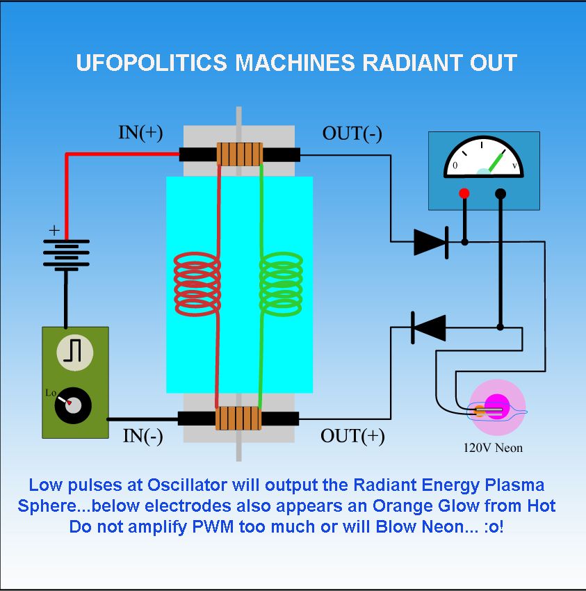
                                Is this the circuit you are trying to replicate


                                There are 2 coils the green is the Cold coil it is wound first then the Red coil is the Hot it is wound over the top of the green they are not wound together


                                I had no success replicating Bob's Oscillator so I used/copied UFO's Oscillator the one above on the right is here


                                The Diode's I used here were fast switching but only needed to be 1N4001 or 1n4007's

                                I hop this helps

                                Kindest Regards

                                Kogs Trying to help

                                Comment

                                Working...
                                X