 Tweet
Tweet
Originally posted by Holbi
View Post

[IMG]
 [/IMG]
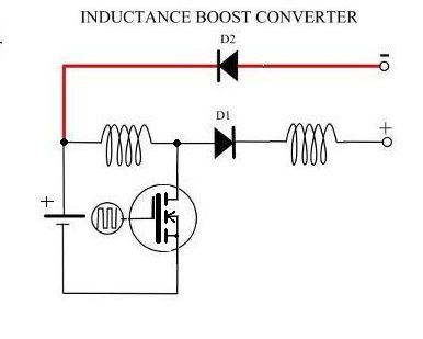
Notice you are only "sending" or Redirecting North Poles to a Common place...Plus the Axis at Common Field are NOT centered, related to all individual coils...(at least not seen on Top View) it will then originate Four Independent Fields.
[IMG]
 [/IMG]
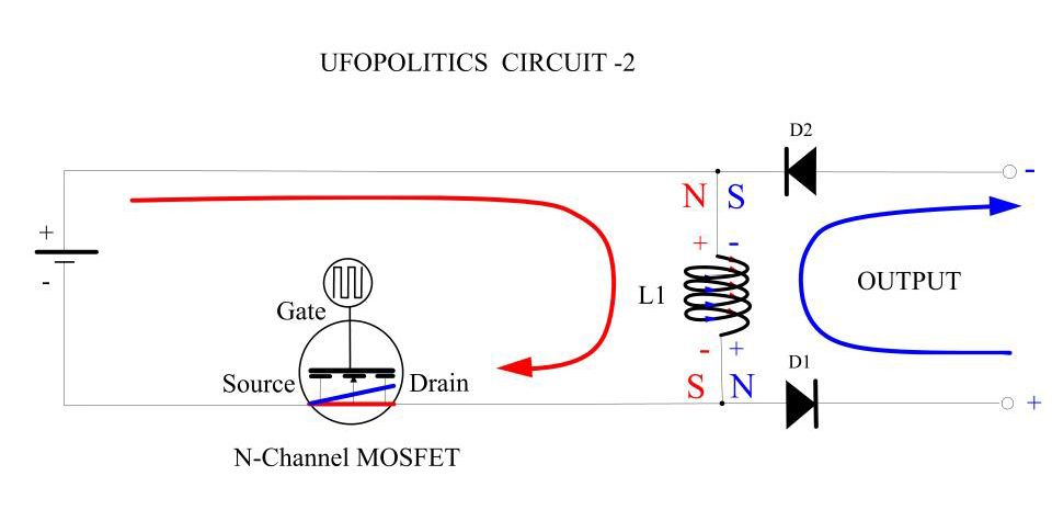
Redirection Elements needs to carry both poles from each individual fields into the common Field like shown above...but that's not all:
S1 Redirecting Element MUST have same equidistant measurements from green line to end of Common Field Gap as N1 Element.
S1 Redirecting Element MUST be of same MASS as N2 Element...otherwise Poles will not be "balanced" (strength, size, area) at end gap.
S1 and N2 Elements does not need to be separated...but made of same core. However, at end extremes they MUST be separated with an air gap, in order to produce Field in that space.
Now, if we pulse both generating coils (light blue) simultaneously, we will obtain the Sum of both fields at common gap...BUT, if we pulse them at different times with equal feeding pulses...then Common Field would be equal to each coil Field along Time.
And...even though we are redirecting fields to a Common Gap/Space...we will always have an "original field" at each coil, at certain timing (beginning and end of pulse) will manifest stronger...realize it will take time (even very short time, nanoseconds) to travel through cores to end gap. This means we will get Radiant Fields ALSO at each individual coil. Therefore, We could collect Radiant Energy at each coil through diodes...

In the Coil displayed at Common Field (the one you named "Output Coil") we collect almost "Pure Radiant", because there is no direct input on that coil...so the induced Hot will be very weak...to our advantage.
The pulsing will be "Out of Phase" in order that there would always be -at least- ONE COIL ON, keeping a Hot Magnetic Field manifested at Core Gap, this will maintain Radiant in a "stand by" Space surrounding that field...while derivative fields from radiant will get "sucked in" through Off Timed Coils.
This way We are creating several "Gates" for Radiant to exhaust...while keeping a Main Field on at all times.
Note: I have just displayed two coils for sake of simplicity...simple Geometry...many could be added, reducing duty cycle per individual coils.
Regards
Ufopolitics


 "Knowledge is as good as it used."


Comment