Announcement

Collapse
No announcement yet.

My Motors got me to Tap into Radiant Energy

Collapse
X
 
  • Filter
  • Time
  • Show
Clear All
new posts

  • Originally posted by sampojo View Post
    Looks very well engineered! So you use the heatsink as the best connection point. I already have the center pin in place, no harm I suppose. putting some heatsink SILVER compound on order! I suppose I could beef up that connection a little too. Going with some stranded wire and filling up those pads with solder!

    thanks Kogs
    G'day Sampojo
    I am not sure the heatsink compound is silver based it is for electrical transfer to make sure there is a proper connection

    Yes build up the pads
    Dana was the first to replicate the JS Monster and he built up the pads with heaps of solder, JS said that that is what you need to do as if I remember correctly he said it also acts as a capacitor

    The stranded wire is very important to use a DC wire like what is used for solar power it is high energy transfer wire as it has a lot more and finer strands than ordinary hook-up wire or wire that transfers AC

    It is always best to use this wire cables any where you use DC and especially if you want efficiency use larger cables not smaller cables but do not go too large do not over do it

    Kindest Regards my friend


    Kogs still getting there
    Comment


    • My Monster Driver Board 1

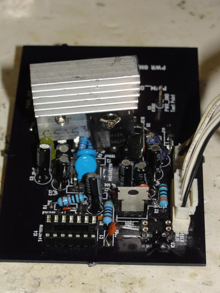
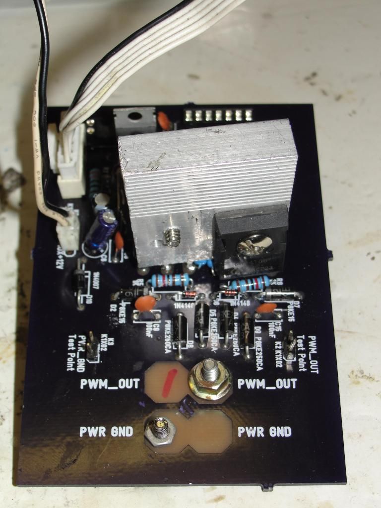
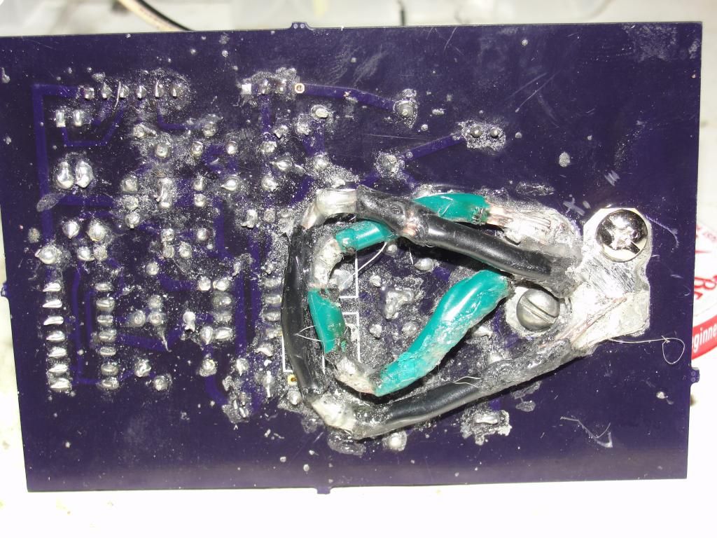
      whew, some of the toughest soldering job I ever did on the 12ga wire, used a micro-torch on my 1000w soldering gun to get the heat needed.


      beat hell out of the insulation huh? Got some cleaning to do on those solder shavings, did some grinding on the pads.

      top vw


      conn. vw.


      Maybe I will try using the heat sink as the PWM out (drain) to avoid the extra soldering job as I understand Kogs did it. Could have lost the whole board there...
      Last edited by sampojo; 07-20-2014, 05:55 AM.
      Up, Up and Away

      Comment


      • My Monster Driver Board 1

        whew, some of the toughest soldering I ever did on the 12ga wire, used a micro-torch on my 1000w soldering gun to get the heat needed.


        beat hell out of the insulation huh?

        top vw


        conn. vw.


        UH-OH Error, see those 1.2K ohm resistors, should be 1.0K!!
        Maybe I will try using the heat sink as the PWM out (source) to avoid the soldering extra soldering job. Could have lost the whole board there...

        Have only tested the regulator output so far; A-OK. Dual NAND not installed here...
        Last edited by sampojo; 07-24-2014, 04:14 AM.
        Up, Up and Away

        Comment


        • Originally posted by thx1138
          Does stranded vs solid make much difference when we are dealing with pulsed DC?

          I understand the concern in a photovoltaic power system that outputs continuous current but would it make any difference in this circuit?

          Would it make sense to use Litz wire in this application? Either on the circuit board or between the circuit board and the motor?
          G'day thx
          My understanding is that with DC current you have the problem with Voltage drop even over short distances one way to alleviate this problem is to reduce the resistance in the wire.
          I understand the majority of the current is conveyed on the surface of the wire and this can be increased by having multiple strands this in turn reduces the resistance. so rather than one single wire the more strands the less resistance the finer the wire the more strands the more surface area

          The reason Solar systems use this type of wire is that they are trying to harvest as much energy as they can and the less resistance in the wire the more current there is.

          I hope this makes sense

          As far as using Litz wire I do not really know except that John Stone has said that twisting the wires between some components reduces cross talk electrical interference between the wires

          Kindest Regards

          Comment


          • Arctic Silver paste disappointment

            Kogs

            I was so enamored that this paste had silver in it that it was of course for heat and electric conduction. But no, it is only heat conductive. should have read the full info on the product. So still looking for heat & electric conductive paste to implement use of the heat sink instead of doing 2 of those heavy gauge solder jobs per board. Trying desperately to implement your design modification!

            Do you think it would work ok with just metal to metal, Mosfet back to heat conductor, at least for low amp small motor applications? I guess all bets off on the 10-20A range for large motors?
            Up, Up and Away

            Comment


            • Originally posted by sampojo View Post
              Kogs

              I was so enamored that this paste had silver in it that it was of course for heat and electric conduction. But no, it is only heat conductive. should have read the full info on the product. So still looking for heat & electric conductive paste to implement use of the heat sink instead of doing 2 of those heavy gauge solder jobs per board. Trying desperately to implement your design modification!

              Do you think it would work ok with just metal to metal, Mosfet back to heat conductor, at least for low amp small motor applications? I guess all bets off on the 10-20A range for large motors?
              G'day Sam
              How's your hip my knee is still sore I am sorry I had it done

              The Mosfets
              The drain pin and the back are connected if you want the Mosfets separated that is each Isolated so they are independent from each other you need a silicone pad to isolate it/them from the heat sink so there is no electrical connection also this pad can squeeze to accommodate any irregularity that stops the heat transfer,
              Where the drain's of the Mosfets are in parallel and you don't need to separate them you need heat-sink paste to make sure there is a proper connection between the back of the Mosfet and the heat sink any little bit of dust can isolate the connection and therefore they will fail. So you must Use the heat sink Paste it will conduct the current. After connecting a Mosfet to the heatsink using a DMM to check for continuity

              If you do use the drain directly to the heat sink you can cut the drain pin one less to solder. Also the heat sink MUST NOT be an anodized one as the anodizing WILL NOT transfer the current


              I hope this is of some help
              Kindest Regards

              Kogs still around

              Comment


              • Found Monster Driver 5.1 PCB at OSHPark.com!

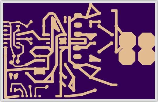
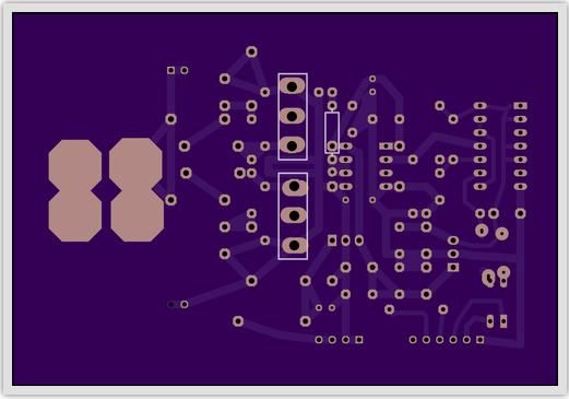
                Looks like Neal got his project search engine working right. Need to correct the mis-statement that they weren't there anymore a few pages back. I sent him the version that has the 3 links. I had to adapt the gerber files for his system Those gerber files found on my dropbox here formatted for Oshpark. His site does 2-layer boards, while the PWM MD5.1 is just single layer, so you have to adjust the file names and dupe one out for a false second layer. He intends to offer them so they can be purchased without the submission of the gerber files any time now with a redesign of his web site. Here are all the layers:

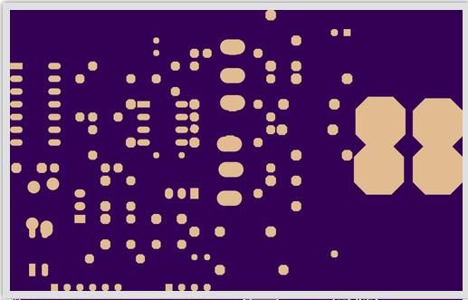
                Wire traces:

                Drill Holes:

                Copper Masks:

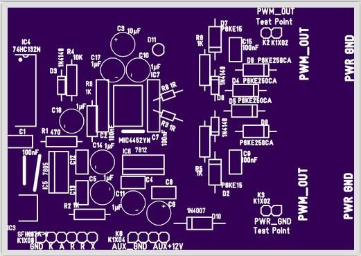
                Component Info:

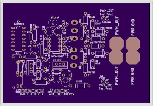
                All assembled layers:


                John Stone MONSTER DRIVER Boards are available at OSHPark without upload under the Shared Projects link!!!

                If any can point me to the updated Monster Driver files, let me know...
                Up, Up and Away

                Comment


                • Assembling the PWM with Arduino Uno

                  Planning on using program Duoblink2ver1 initially, growing into the quad for my quad motor. I see how it is essentially using pins 10 & 11 to drive a 2-stator motor, pins A1, A2 as pot inputs for Duty cycle and frequency. I just can't tell how to hook up to the Monster Driver board.

                  Do I use the opto A or K pin input there?
                  Last edited by sampojo; 07-29-2014, 04:00 PM.
                  Up, Up and Away

                  Comment


                  • thanks for asking

                    Originally posted by iankoglin View Post
                    G'day Sam
                    How's your hip my knee is still sore I am sorry I had it done
                    Pain from incision going away after 4 wks. had the "anterior" hip replacement, no muscle cutting, somewhat traumatic since they then struggle to keep vertical 4" incision as small as possible, so they go in heavy with retractors to make a round hole as big as possible, but at least muscle strength not compromised as a result, no post-op restrictions, but did have circulation probs and some swelling. They delayed my PT until post-op visit, 3 wks, kinda think that was a good idea, area just not ready. Free and clear from here methinks.
                    Sorry about the knee, give it more time and fight thru the PT as long as it feels better after...

                    a small medical aside
                    good luck on that the the green monster and the knee!
                    Up, Up and Away

                    Comment


                    • John Stone's MD 5.1's Is blown

                      G'day UFO, John Stone and team

                      I wanted to finish my Bicycle put it together using J Stone's Monster driver and test it before I finish Nessie.

                      In the Bike I have the 4 Gates each 2 set 180deg. in parallel so I had 4 wires out from the motor I connected the 2 Positives together and the 2 negative ones I connected so as to have 2 switches as per UFO's diagram for Nessie

                      I have a bank of 10 - 63v 22000uf Electrolytic Capacitors in parallel and connected in parallel with the Battery which measured 52v

                      I needed to have a DPDT switch to switch the battery and the cap banks separately as if you keep them connected when not in use the caps will drain the battery
                      So I used 2 - 24v 80 amp 5 pin Relays to do this switching the 52v+ Positives from the Battery and the cap bank to their own Relay and joining them after the Relays so they are connected jointly to the motor and to the both positives of the gates I connected the Extra Diodes across the switching Connectors but as I did not as yet receive the 10 watt resistors I have not connected them

                      This worked fine when I had my bike on its side and there was no load but when I road tested it I made sure I had some speed probably 5 k's/hour then switched on the motor slowly turned the throttle it accelerated for a bit then blew the Mosfets

                      Please John Stone and UFO I know you both are very busy I have up loaded some Pics to my Photo Bucket here and would like if you might suggest where I have gone wrong

                      Bicycle Controller Blown Slideshow by Kogs1 | Photobucket

                      All the other components The regulators, PWM Oscillator are still working OK

                      Kindest Regards


                      Kogs still around

                      Comment


                      • Kogs

                        I see that you are only using one mosfet in each of the two locations on that board. I switched to two at each locations and have not blow another one.
                        Dana
                        "Today's scientist have substituted mathematics for experiments and they wander off through equation after equation and eventually build a structure which has no relation to reality."
                        Nikola Tesla

                        Comment


                        • Originally posted by iankoglin View Post
                          G'day UFO, John Stone and team

                          I wanted to finish my Bicycle put it together using J Stone's Monster driver and test it before I finish Nessie.

                          In the Bike I have the 4 Gates each 2 set 180deg. in parallel so I had 4 wires out from the motor I connected the 2 Positives together and the 2 negative ones I connected so as to have 2 switches as per UFO's diagram for Nessie

                          I have a bank of 10 - 63v 22000uf Electrolytic Capacitors in parallel and connected in parallel with the Battery which measured 52v

                          I needed to have a DPDT switch to switch the battery and the cap banks separately as if you keep them connected when not in use the caps will drain the battery
                          So I used 2 - 24v 80 amp 5 pin Relays to do this switching the 52v+ Positives from the Battery and the cap bank to their own Relay and joining them after the Relays so they are connected jointly to the motor and to the both positives of the gates I connected the Extra Diodes across the switching Connectors but as I did not as yet receive the 10 watt resistors I have not connected them

                          This worked fine when I had my bike on its side and there was no load but when I road tested it I made sure I had some speed probably 5 k's/hour then switched on the motor slowly turned the throttle it accelerated for a bit then blew the Mosfets

                          Please John Stone and UFO I know you both are very busy I have up loaded some Pics to my Photo Bucket here and would like if you might suggest where I have gone wrong

                          Bicycle Controller Blown Slideshow by Kogs1 | Photobucket

                          All the other components The regulators, PWM Oscillator are still working OK

                          Kindest Regards


                          Kogs still around
                          Kogs,
                          Looking at the layout of the board it looks like the two power mosfets are inserted backwards from each other. Pin 1 is in the center for each one.
                          It appears that yours are both in the board the same way and mounted on the same side of the heat sink am I wrong?

                          Comment


                          • I see you have them in backwards from each, but that must make them hard to heatsink properly. You do have a fan on it that should help. Do you have a BEMF diode(s) across the motor,as the brush leaves the commutator you can get a large spike back into the output transistors that tends to blow them. Just trying to help out.

                            Comment


                            • Originally posted by prochiro View Post
                              Kogs

                              I see that you are only using one mosfet in each of the two locations on that board. I switched to two at each locations and have not blow another one.
                              Dana
                              G'day Dana
                              I had already a JS Monster with double Mosfets I used it sometime ago on various testing it worked I did not see any real difference I was told by several persons that only one Mosfet should be enough to drive a 250w motor so I continued making them with just the 2 Mosfets as JS designed it
                              it is to cater for 200v 100a I realise that it needed finer tuning with the 1 ohm resistors.
                              That being said I connected it up to my motor and it worked OK I then connected to it up to the circuit that I was using for Nessie and as soon as I started the motor it blew the Mosfets at least that is what I imagine as I have not pulled it down to test it yet.

                              I notice that the LED adjusts to the PWM as I turn the pot but the motor is not effected it just goes full bore So I am sure it is the Mosfets.

                              I am now convinced that it is some how connected to the Capacitors.

                              I have though connected them in parallel to the battery with the Diodes just as UFO has stated in Nessie's circuit

                              It may be that the caps draw from the battery in the first instant and probably it may draw through the controller

                              Perhaps I need another diode to redirect the current from the battery

                              I really need to sort this out before I start putting Nessie's works together

                              I have purchased 50 pcs 2.7v 500F super capacitors and they should be arriving sometime within the week.
                              I will be experimenting with them they will make 2 banks 13.5v 500F each I was going to put these in series to give me 27v bank I could run with a 24v system

                              If it is the caps that are the problem and when I have them sorted I will be a happy chappie.

                              I have to get going and replace the Mosfets and get Sorted

                              My wife says I need to get all these things sorted as she wants to sell the house and move to Tasmania.

                              Kindest Regards

                              Kogs slowly getting there

                              Comment


                              • Originally posted by Pembelton View Post
                                I see you have them in backwards from each, but that must make them hard to heatsink properly. You do have a fan on it that should help. Do you have a BEMF diode(s) across the motor,as the brush leaves the commutator you can get a large spike back into the output transistors that tends to blow them. Just trying to help out.
                                G'day Pembelton
                                Thanks for your input
                                I have been using these JS Monster drivers also the drivers that UFO showed us 2 Years ago, for some time now and have never had this problem it seems now I am using a Cap bank I have this problem.

                                I think you are right the only problem with that is we are collecting the energy produced by the Motor and directing this back to the battery via the caps

                                Kindest Regards

                                http://i1193.photobucket.com/albums/...9x89_57418.gif
                                Kogs Photo Bucket does not work again

                                Comment

                                Working...
                                X