Announcement

Collapse
No announcement yet.

My Motors got me to Tap into Radiant Energy

Collapse
X
 
  • Filter
  • Time
  • Show
Clear All
new posts

  • Re: Prochiro; Battery Negative vs. Gnd. ie Driver/Arduino ground sharing

    Well a lot of gremlins are running through my mind on your post Dana! I would have assumed that the GND on the Monster Driver would be connected to the Arduino GND for starters.
    1. Should these boards share a common ground?


      Here you say:

      Originally posted by prochiro's previous View Post
      The K is your negative. This negative must be fed with a negative wire which goes back to battery and is not to be united with any other ground wire until it gets to the battery.
    2. The battery you mention here, is that assuming that it is the battery being employed to run the Arduino and Monster Drivers, NOT to be confused with the battery(ies) driving the motor?

      The Arduino can take up to 20v for power and the Monster Driver should have more than 12v also. In my Asym Motor Controller, I was going to allow use of battery or a 110vac plug-in transformer wall wart based power supply, gets 18.5vdc.
    3. Is "battery negative" in your statement the same as a power supply negative for the electronics then?

      I could see there could be a need for the signal return to its negative, to the Arduino. That would seem to go to its GND pin. Once it gets there I think it is then be shared to the other Monster Driver boards, if these GND's are all connected, and then they also become interconnected to the battery(ies) GND (negative terminal) driving the asymmetrical motor. Thus it would seem the system is all grounded together. The ground on the input pin cluster is common to the PWM GND.
    4. Is it important that some ground connection NOT be made between these boards? If so, which specifically?

      OK Somebody turned on the light, where is the smiley face with the lightbulb?


      NO ground connection between the arduino and Monster Drivers, BC that is why we are using an optocoupler after all, to isolate the signal generating Arduino from the radiant energy gremlins roaming around the Monster Drivers!
    5. Dang, then I need 2 independent power sources/supplies for my Asym Motor Controller, one for the drivers and one for the Arduino?

      !#@$
    Last edited by sampojo; 08-02-2014, 12:47 AM.
    Up, Up and Away

    Comment


    • Sampojo

      Sorry, for the confusing post but you got it right now. When I used the word, Battery, I was talking about the general way the opto works. I posted too fast as I was just taking a break from cutting wood and was in a hurry. I went back and added the battery in this case is the arduino signal. It does need its own battery and just sends the pulse signal into the Monster. This signal is small and just strong enough to get the job done. Once the signal is on the monster board, the 15-18 volt power from its supply is added to arduino signal to fire the fets. The third power supply is your big battery bank and goes thru the fets as they are turned on. Yes it is harry but you are getting it now. All batteries remain separate with the exception of the opto contact at A and K, which because of the opto is not really a connection. This complicated system is necessary to protect all the units involved. That pair of heavy gauge triangles is carrying too many amps to be flowing thru the monster board itself. Those other extra parts I see on some boards posted are increasing the length between the fets and the large battery cables to the motor. This is not good at all and every joint between these parts causes loss. This will show up and fail on larger Imperial projects. Stick to the boards at O-Park or print your own on salvage military stock which has heavy copper, put all on one board if you want to, but don't change the circuit. Keep a copy of Johns PDF in front of you after you get them going and reread then. Then you will get even a better idea of what is going on inside that thing and see that it was well built and can be trusted.

      Dana
      "Today's scientist have substituted mathematics for experiments and they wander off through equation after equation and eventually build a structure which has no relation to reality."
      Nikola Tesla

      Comment


      • thx1138
        As I understand this circuit, the diodes around the MOSFETs keep the "radiant energy gremlins" from the driven motor's coils collapsing fields within the circuit that is being switched
        This is true unless you blow a fet and loose diodes, we have seen this happen. When it does you may loose one or both of 7805 and 7812 as well as any other piece on the board as lighting can strike anywhere.

        Since we have both +5V and +12V circuits on the Monster Driver board that aren't being affected by the "radiant energy gremlins" I believe it's possible to power the Arduino from the same source that powers the monster Driver
        As they aren't being affected by the "radiant energy gremlins as long as nothing goes wrong, you are correct. But in the case something does go wrong, you lose an Arduino as well. So if you blow a fet, the cost of repair and time lost more than doubles. If you take this route, have as many Arduino's on hand as you have extra fets. You can however use the same battery and add a separate 7805 to power the Arduino as long as that circuit is totally separate. This should have its own power leads that go clear to the battery terminal.

        Dana


        Last edited by prochiro; 08-03-2014, 06:01 PM. Reason: clarification
        "Today's scientist have substituted mathematics for experiments and they wander off through equation after equation and eventually build a structure which has no relation to reality."
        Nikola Tesla

        Comment


        • Thx1138

          You are correct on all counts, specially the heat sink part. Good eye. Also I still recommend to all that you NOT use the heat sink to carry current as it will heat up and further cause fet failure.
          Dana
          Last edited by prochiro; 08-04-2014, 05:33 PM. Reason: confirm statement
          "Today's scientist have substituted mathematics for experiments and they wander off through equation after equation and eventually build a structure which has no relation to reality."
          Nikola Tesla

          Comment


          • Re: Cornboy comment on neons to detect too much RE

            Originally posted by Cornboy 555 Post 2838 View Post
            Hey Kogs, don't know if it will help, but try placing 3 small 90v neon's in series across the drain and source, to physically monitor the back flow, if they are flashing, you are heading for a crashing!!!.

            Regards Cornboy

            Hey Cornman!
            1. Why the 3 neons, the RE voltage is too high for one?
            2. Would this be on an Imperial style machine?
            3. Could I get away with one NE-1 on smaller motors?


            I am building a motor controller and want to run an indicator out to the front panel.

            TIA

            Sam
            Last edited by sampojo; 08-04-2014, 05:35 PM.
            Up, Up and Away

            Comment


            • Re: heat sink as part of circuit

              Originally posted by prochiro View Post
              Thx1138

              You are correct on all counts, specially the heat sink part. Good eye. Also I still recommend to all that you NOT use the heat sink to carry current as it will heat up and further cause fet failure.
              Dana
              Roger that, I used that design. I had all those concerns, but as I just want to run smaller motors first, (1-3A), I just want to get the driver working first, and wanted to avoid the solder torture once. I guess I will remove the wire on the heat sink. But I am considering using a fan too. I am scrimping on the heat sink size at the moment but will be looking to go larger as I get my Baldor frame 56 Unipolar built.
              Last edited by sampojo; 08-04-2014, 05:54 PM.
              Up, Up and Away

              Comment


              • Re: Monster/Arduino Grounds, an additional point

                After rigging an additional power supply, I notice now that at least concerning the opto K return line, it seems that it must be shared to all monster driver grounds. Should be no surprise as these grounds all lead to the power ground on the battery pack return terminal, negative.

                Dana/Bruce, correct?
                Up, Up and Away

                Comment


                • Arduino does not share a common ground

                  @Sampojo

                  Sam, the Arduino is completely isolated from the common ground on the opposite side of the opto isolater. Read John's tutorial on this section and it will clear it up in your mind. You can power the arduino with a 9 volt battery or a plug in wall charger. The Arduino is connected to K1 pin 5 Rin and the Arduino ground is connected to K1 pin 2. The ground that is on K1 pin one is connected to the common ground of the monster drive. Do not connect the Arduino to that pin!

                  Cheers

                  Garry
                  Last edited by GChilders; 08-05-2014, 02:59 AM.

                  Comment


                  • Re: grounds

                    Okeydokey! thx thx
                    Up, Up and Away

                    Comment


                    • My Asym Motor Controller

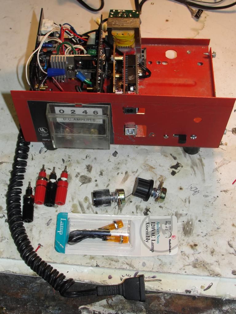
                      Assembly nearing completion.


                      This shows Monster Driver boards 1&2 and Arduino with prototype installed and wired. External connectors and freq/duty cycle pots still need connected to A0/A1 on Dana's duoblink program, designed to use pins 10/11 for PWM. The hardware is designed to use 9-12 pwm pins for a quad stator application.

                      Notice the 2 wall wart power supplies, stacked one on top of the other. The smaller on top is supposed to be a 9v power supply, putting out nearly 14v unloaded. When it powers the Arduino it is dropping down to 6v, which they warn could cause a problem on the 5v power on the board.

                      Planning MD boards 1&2 will have terminals on the left. I think I will try to squeeze in the neons there just wired between each board's exterior post connectors. I would like to put in a digital ammeter but have suspicions it will not measure correctly since it may be trying to sample a PWM wave. All hit or miss in the digital sampling game then.

                      What a miss on the first holes I made for the Arduino jacks! Plan on bringing a power supply jack out for the Monster drivers too, so a battery pack can be hooked up on both in lieu of 110vac.

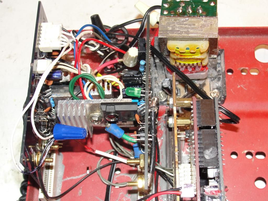
                      This is a close up of the boards.


                      One of my voltage regulators comes very close to the other board's heat sink. Can't be good if it touches...

                      I am pretty busy tomorrow and may not finish. Only board 1 has any circuit testing at all, VRs A-OK there. Planning to get my PC O-scope on the job...
                      Last edited by sampojo; 08-05-2014, 04:43 AM.
                      Up, Up and Away

                      Comment


                      • Thx1138
                        John Stone was asked this question and there were many reasons to NOT put a fuse in.
                        1. Yes the fuse is a resistor which is asked to melt at a specific level. This robes power from our board.
                        2. They at minimum take .5 seconds to blow. This is way to slow to help save your work here.
                        3. There must be an exact fuse blow out range, too large and no blow, too small and blows for no reason. With these then it must be exactly matched to the specific motor used and highest current expected. This is not an equation easily calculated.
                        4. Just forget about it...........
                        Dana
                        "Today's scientist have substituted mathematics for experiments and they wander off through equation after equation and eventually build a structure which has no relation to reality."
                        Nikola Tesla

                        Comment


                        • Re: extra wires

                          Originally posted by thx1138
                          You need to get the green, white, red, black, and blue wires that are between the heat sinks relocated before you fire it up. I couldn't tell if they are connected to anything or just stuck there temporarily but if they are left there and the heat sinks get hot the insulation will melt and create a direct short to the drain of the MOSFET(s).

                          I'm guessing you knew this but sometimes we forget to undo the "temporary" things we do for expediency. I've done it myself so just wanted to point it out.
                          That hot huh?

                          One connector with those wires are that extra circuit for hookup that JS put in that I don't understand, extra grounds etc. 6 pin pin-out so put in a 6-pin wired connector. Just gettin' in the way now. I wasn't gonna worry about heat right off since I am just looking to run my smaller motors, 1-3 amps. Need to redesign my Quad pent window motor with a new unipolar rotor(planning a bifilar 32ga winding), eventually doing my Baldor. In the mean time still need to build 2 more drivers...

                          So how much troubleshooting do these Monster drivers need to get them working?

                          Any luck working on first try?

                          Think I will try final AMC construction steps now...

                          thx thx!
                          Up, Up and Away

                          Comment


                          • Tx1138

                            That resistor you are talking about is not going anywhere and is not needed. John S. put it there in case we did need it but we don't. Limiting the Arduino signal is something you do Not want to do. That signal is just enough to trip the opto as it is. John put several pins on the board that were not needed in the end so just leave them alone. Follow the circuit diagram to the letter and ignore extra holes. The led on the board already will tell you if the fet is going off. You do not need any other to test.
                            Dana
                            "Today's scientist have substituted mathematics for experiments and they wander off through equation after equation and eventually build a structure which has no relation to reality."
                            Nikola Tesla

                            Comment


                            • Originally posted by sampojo View Post
                              Hey Cornman!
                              1. Why the 3 neons, the RE voltage is too high for one?
                              2. Would this be on an Imperial style machine?
                              3. Could I get away with one NE-1 on smaller motors?


                              I am building a motor controller and want to run an indicator out to the front panel.

                              TIA

                              Sam


                              Sorry Joey, I missed this post, the Fets on JS. Monster supposedly can handle 600 V, three 90v neon's in series will let you know when the backrush reaches around 300v, depending on the brightness that they are lit to.

                              If they are very bright and blow, Guess what is next, and very quickly, probably before you can push any buttons?

                              Regards Friend, Cornboy.

                              Comment


                              • thx1138

                                Before the monster was developed we tried a lot of stuff including the 555 timer and other types of microelectronic controllers. For several months we went back and forth and decided upon all using the Arduino as it was a reliable timer and could also handle the other required sensors such as heat and rpm control that we needed. We felt that if everyone was using just any kind of timer that they wanted that further teaching and program control would be difficult. The 555 has not the durability nor the compatible excessaries of the Arduino. If you follow the 555 or PIC uController route I think that you will be limited in advice from the more advanced builders and your testing of system functions may not be easy when we once again use programing. You can of coarse use what ever you want but when we all advance to program control you will be on your own with that code.

                                The Arduino has built in resistance which can be controllable on most lines. The issue with the opto is not limited capacity but is getting enough into it to make it work reliably.

                                Dana
                                "Today's scientist have substituted mathematics for experiments and they wander off through equation after equation and eventually build a structure which has no relation to reality."
                                Nikola Tesla

                                Comment

                                Working...
                                X