Announcement

Collapse
No announcement yet.

My Motors got me to Tap into Radiant Energy

Collapse
X
 
  • Filter
  • Time
  • Show
Clear All
new posts

  • Sampojo
    You are correct as aside from the motor wires connected thru the fets, your circuit is complete. You are going to need a fan in there to cool the fets also. The closer to direct direct air flow the fets are the better. If you have a top for your complete box you could mount a fan in that and push air out of the box and let air in thru an opening that caused air to move over the fets directly. I also see that you are using two fets on the board and you may need more room for all four boards and more room for each as you will want fets on both sides of each board for a min. of 16 fets for the imperial.
    Dana
    "Today's scientist have substituted mathematics for experiments and they wander off through equation after equation and eventually build a structure which has no relation to reality."
    Nikola Tesla

    Comment


    • Thx1138
      You obviously do not still understand the monster circuit yet. Take another look at the resistor directly attached to the led. There is nothing wrong with the monster circuit as John Stone has printed it and there is also nothing wrong or that needs to be changed with the PCB boards we use. You guys have spent a lot of time trying to change the layout for this reason or that. Just run the dam thing. There is also nothing wrong with the Duoblink program. If anyone has a problem with it or the board, it is because they made a mistake or have done poor work.
      Dana
      "Today's scientist have substituted mathematics for experiments and they wander off through equation after equation and eventually build a structure which has no relation to reality."
      Nikola Tesla

      Comment


      • Troubleshooting MD 5 boards, at the opto

        Hi gang, Well didn't get far, nice waveform going into Ardiuino hookup A & K, transferring OK to A & K pins on the optocoupler. E pin pegged at 5v, C pin 0v using the MD5 ground, no detectable signal. I am using a Hantek PC oscope. Tried another opto, same thing. LEDs not lit/flashing on boards. In this picture with the ICs removed, I am testing at the links by the 4-pin socket, which are my E & C pins.


        Still trying to figure out the pins on the NAND gates to look at... and the FET driver for that matter. But ran the probe around them, didn't see anything. Power 12v there I think.

        John Stone went over this very nicely for Cornboy in post 2316, P 78.

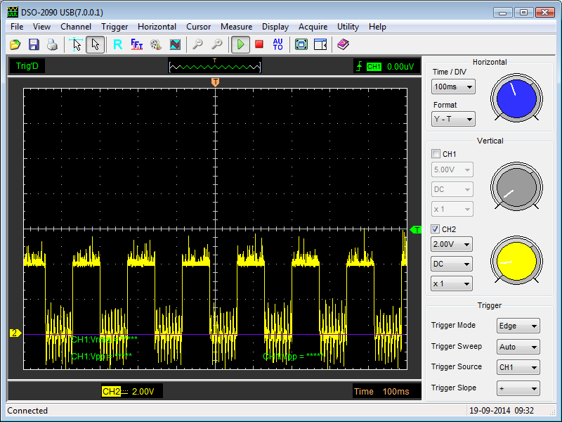
        Wow, this can't be good, switched Arduino ground to board cable to pin K on the connector and got this:

        Edit: Clarification, hooked up to Ground LINE for Arduino, shared out to boards 1&2!


        bybye nice clean square wave. Am using twist connectors there, changing to solder...


        Redoing very carefully many solders... NAND gate has 5v on several pins, seems normal.

        Reading post 2316 very carefully, will see if my arduino signal generator can go to a 1HZ signal!
        Last edited by sampojo; 09-21-2014, 02:14 PM.
        Up, Up and Away

        Comment


        • Found a connector problem on board 1

          Whew, looks like I connected to Rout and Opto A pins when I was trying to get Opto A & K. I was getting signal on pin 3 of the opto, so I had Arduino ground and signal crossed too! Board 2 dunno yet.

          Edit: I think I inverted the pin order when I made the connector and started counting pins from the wrong side.

          But my main concern at this point is Dana's and thx's disagreement on feeding the opto straight from the Arduino. John Stone is seeming to address this in the italics below when helping Cornboy.
          Originally posted by JohnStone 2316 Post View Post
          Explanation of opto function:
          The opto input is a simple LED (IC3 pin 1,2). If you operate it without resistor in series it will die like a normal LED.
          This LED emits light inside the sealed housing of IC3. At pins 3,4 there is connected a simple transistor. And now I explain the opto trick! This transitor has no base leg and under normal condition it would be not possible to control it. But the base of this transistor is uncovered and receives photons (light particles) from built in LED. The energy of these photons performs the miracle that our transitor decides to perform its switching function.
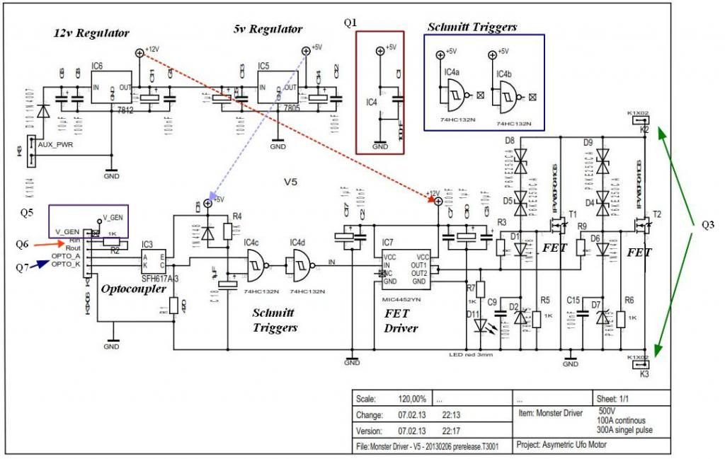
          Is John saying what thx is saying, and now we know why his connector has Rin and Rout on the schematic? We should route the input through the 1K resistor called for there? Or else burn-up of opto LED may occur? Hate to be buying more of those, so leaning toward using Rin/Rout.

          Here is the schematic, annotated with the red arrow for this matter:

          NOTE: R1 is now changed to 330 ohm
          Last edited by sampojo; 09-21-2014, 02:03 PM.
          Up, Up and Away

          Comment


          • 1000 ohm resistor kinda High?

            the starter kit for theArduinio furnished LEDs and resistors for test circuits, Those resistors for the LED circuits are only 200 ohms. I used them for all my tests, worked very well. I will have to run some 1000 ohm circuit tests...
            Up, Up and Away

            Comment


            • Problem IC4 quad NAND gate, no pulsing pins

              Originally posted by JohnStone post 2317 View Post
              4.
              - Assemble IC4
              - Connect your generator with 1Hz signal
              - Switch on power at your PCB

              Measure IC4 pin 8, 12, 13 to be pulsing (0V, 5V)

              5.
              While your PCB running - short circuit C18

              Measure IC4 pin 8, 12, 13 to be stable high (5V)
              This would be the disable condition at very first milliseconds after switching power on.

              JS
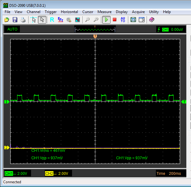
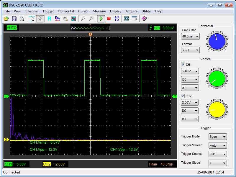
              Getting solid 5v as if C18 is shorted (its not), pins 8,12,13. here is my input signal at 1v~ from the opto after being trimmed through R1.


              Its a little noisy, my jumpers on Rout-OPTO_A must be like little aerials, trying to save wire on the connector... Hmm the scope shot is on the output side of the opto, but it looks a little cleaner than the input side,(Vpp=1.5v). I am assuming it is clean enough at the moment. same behavior both boards.
              I think I will try in putting two 5v signals on the gates to get the output to flip and see that in operation.

              whew, glad I didn't do this, max input for that gate is 3.5v!
              Last edited by sampojo; 09-24-2014, 02:48 AM.
              Up, Up and Away

              Comment


              • Re: thx post, Quad NAND prob cont'd.

                yes still using the duoblink. Since using R2 1000 ohms, it is knocking the Arduino input as I stated down to 1.5v. We are dealing with not insignificant current, enough of course to drive the LED in the opto. Coming out the other side I get the 0.937 value. Looking at the Datasheet I see some threshold voltages mentioned, like 1.5v min, 3.5v max when Vcc is 4.5v. Not sure I understand it all, but that nominal value of 2.38v seems to agree with your statement. I originally took the first line which had a .7v min threshold but that was for 2v Vcc. So 1000 ohm resistor looks a little high to me, expecting if we send more voltage into the opto A-K, we get more out of the E-C group. It will be a couple days to get back to it.

                thanks thx
                Last edited by sampojo; 09-24-2014, 02:39 AM.
                Up, Up and Away

                Comment


                • Sampojo
                  If you are going to use R2 at all, you have 1000 ohms giving vary little voltage, correct. We have been thru all this before but I will guide you to success. We need as much of the voltage as we can get to get through to make things happen further on the board. The trick is to put lower and lower ohm resisters in there at R2 until you are reading from 3.5 to 3.7 volts from opto output. At that point you can do no better. This is something that each board has to be tested with. Now, most know that I have huge solder applied over all board lines and connections. For me this does add capacitive value and safety. For me, the value of R2 is zero. Most others found that 200 to 100 ohms were just fine. I would put regular resistor of 200 ohms in yours, test the output voltage and get on with it.
                  The Duoblink program is for two boards operating at same time, not one board. A simple square wave program with two pots for freq. and duty is what you use for the single testing. Both will run your motor but the pulses will be every other one used with the Duoblink because of internal timing.

                  Dana
                  "Today's scientist have substituted mathematics for experiments and they wander off through equation after equation and eventually build a structure which has no relation to reality."
                  Nikola Tesla

                  Comment


                  • thx1138
                    Resistor - Wikipedia, the free encyclopedia


                    "A resistor is a passive two-terminal electrical component that implements electrical resistance as a circuit element. Resistors act to reduce current flow, and, at the same time, act to lower "voltage" levels within circuits."

                    If your intent is to impress anyone, well you are not. If your intent is to help anyone, well you are not, as incorrect information misleads those who do trust you.
                    "Today's scientist have substituted mathematics for experiments and they wander off through equation after equation and eventually build a structure which has no relation to reality."
                    Nikola Tesla

                    Comment


                    • Sampojo current limiting resistor

                      @Sam

                      Sam this week I populated another 3 Monster boards and had a problem with IC4, 74HC132N, not getting enough voltage to pulse the second gate. When John Stone helped Cornboy with his assembly, I followed along and built 2 at the same time. After going back over the notes I remembered John had changed the values for R1 and R2 to 330 ohms. R1 in the BOM of LN004 calls for a 470 ohm resistor and R2 calls for 1K ohm resistor. These two in combination were dropping the voltage of the output of IC3 pin 3 down to 1.6 volts at the peak. It really should be much higher than that for IC4 to operate correctly. Pin 9 was pulsing as it should but pin 11 and 12 were not pulsing at all and nothing downstream was working also. Read the instructions in post 2317 on assembling the section D. John explains why this is a problem in that capacitor c18 does not get filled with enough energy to open the gate at pin 8. I found the problem originated with the low voltage on the Pin 3 of the opto-isolator. I replaced R1 and R2 with 330 ohm resistors and all works fine now. Dana is correct in that a 200 ohm resistor will probably work fine as it is recommended that an LED be operated with Arduino with 200 to 1K ohm resistor. For my printed circuit boards they seem to work with 330 ohm perfectly.

                      Cheers

                      Garry
                      Last edited by GChilders; 09-25-2014, 04:06 PM. Reason: Wrong pin number for opto-isolator

                      Comment


                      • Arduino with Monster Drive, Blink and Fade Programs

                        @All

                        Both the Arduino and monster drives have been found to be reliable with all of these programs. They have been run by multiple individuals on the forum and none have found the program or the monster drive to be at fault. Any failures in the monster drive can usually be traced to poor craftsmanship. Out of the six that I have built personally I had a problem with one pcb. I may have created that problem myself, or there may have been a manufacturing defect in the pcb itself. The fact is that I never got past the power supply section on that one. Had a problem with the 7805 not being grounded properly and never could find the problem even after running the jumper wire that was suspected to be the problem. I replaced the 7805 and still had a problem. There have been occasional failures with the mosfets and I recommend that the neons that are wired across the source to the drain not be eliminated, they are a great safety feature in case of back emf surge that could possibly ruin the mosfet and cause it to fail full open. I also recommend following the advice of ufo in putting a kill switch on any thing you install your motors into in case of a runaway motor because of a failed mosfet. See Cornboys set up where he wired three small neons in series in order to manage the voltage and current coming out of his monster. Better safe that sorry.

                        Cheers,

                        Garry

                        Comment


                        • Solder Bridge at K1 pin 3 and 4

                          @thx1138

                          Originally posted by thx1138
                          The Monster Driver resistor R2 is not connected to anything. You can tell by looking at the traces on the Monster Driver board.

                          I haven't seen the motor driver software yet because I haven't found a download yet but it apparently uses an internal resistor of the Arduino to drive the A pin of the optoisolator through the OPTO_A pin on the header. This is known as a "pull-up resistor" and the software uses different instructions to turn the pull-up resistor on and off than what is used to set the pin on or off in the Duoblink software. That's the difference between the Duoblink software and the motor driver software - those instructions. And that's why you don't want to use the Duoblink software to test the Monster Driver board. The Duoblink software doesn't use the pull-up resistor so there would then be no resistor at all between the Arduino pin and the LED in the optoisolator. John says doing it that way will blow the LED in the optoisolator but I'm not so sure about that when using an Arduino. The optoisolator documentation says it will handle up to 70mA but the Arduino pin will only handle 40mA so I think the Arduino pin would blow first. Maybe both.

                          Dana said in an earlier post that the problem was getting enough current to the optoisolator rather than too much. So if you connected the MD R2 between the Arduino pin and the Opto_A pin that would reduce the current even further and it wouldn't work. It wouldn't damage anything but it most likely wouldn't run either.

                          The Duoblink software requires an external resistor. The motor driver software requires no external resistor because it is using an internal resistor of the Arduino.

                          Can I get a link to download the motor driver software?

                          You have not populated this pcb and are definitely not qualified to give information on it as you do not understand the circuitry at this point. There is a solder bridge between pin 3 and 4 on K1 that connects R2 to complete the circuit for the Arduino and opto-isolator. The Arduino ground is connected to pin 2 of K1 goes through the opto-isolaror(IC3) and then out through pin 3 of K1 through the bridge between pin 3 and pin 4 of K1 then through R2 and back into K1 pin 5 which is called R in which goes to which ever pwm pin on the Arduino that you have chosen to pulse the monster drive with. I have traced this circuit backwards intentionally because the current flows from negative to positive. This completely isolates the Arduino from the monster drive and all other high voltage high amperage circuitry as John Stone intended it to be. I have read a lot of wasted energy on posts by people who have not built any of these devices and parade as experts. Build one, ask for help if you need it after reading the tutorials which are found in the LN004 and in posts 2275 through 2380. There are others where I struggled trying to get my first two together. There are people here to help, but, the information on building them is already on the forum. Utilize that information first. If you do not understand how a circuit works it just may be that you do not have all of the information that is needed. The jumper wires on the pcb and the solder bridge across pin 3 and pin 4 as an example. Did you really think that an electrical engineer of John Stone's standing put that R2 in there without it being vital to the circuit? Please ask questions if you do not understand something and do not make assumptions that only confuse those who are trying to build something that is a bit complex but if broken into doable tasks can be accomplished. I have never built anything as complex as this monster drive but with a little help had success. If I can do it I have to think that most others can also. I wish you good success in your endeavors here. Sampojo's problems were created by misunderstanding as many of our problems are. It was corrected by correct information and understanding as most of our problems are. It is difficult to diagnose the problems someone else is experiencing with their project without knowing what they have done and what their intentions are in doing so. Mistakes are made unintentionally. But a lot of what goes on here has been proven by many different people. I cannot speak for others but I really do not need more misinformation in my life. I do not assume the position of knowing everything about this technology. There have been a host of critics who as far as I can tell, have not picked up a soldering iron or a welder to make these motors and simply take the position of an expert on everything from how these motors cannot possibly work, that the Arduino is going to get fried by the code we are using, that the monster drive will destroy the Arduino etc. etc. etc.. Come back after you have actually built something and have something to contribute to the thread. We really do not need more posers on this thread wasting every bodies time with misinformation.

                          Cheers

                          Garry
                          Last edited by GChilders; 09-25-2014, 05:35 PM. Reason: typo

                          Comment


                          • Making progress, R7 missing on OSHPark board?

                            OK Gang,

                            Thanks Dana, exactly what I had in mind, using 200 ohms on R1, NAND gate sprang to life beautifully, had 4.4v out of the opto, getting 12v out of the MOSFET driver chip and 12v going in to the MOSFET gate.


                            So I think the board will run a motor now. I need to clean up some stuff before I do that. My diode isn't flashing however and has something to do with an open pin on my board bottom. I am missing something.

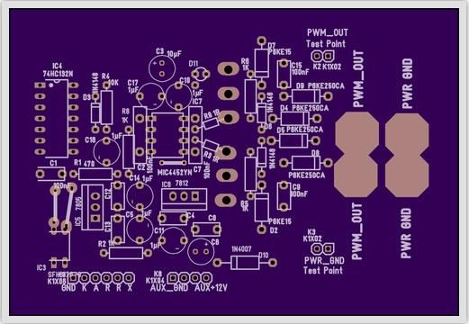
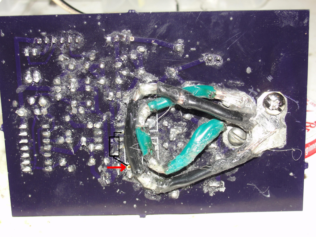
                            There is no R7 diode step-down resistor on the OSHPark board?!?!?


                            You can see I have an open pin + to diode at the red arrow. I traced in where R7 goes.


                            I have been meaning to post a question about that open pin. But better to post an answer.
                            Last edited by sampojo; 09-25-2014, 08:39 PM.
                            Up, Up and Away

                            Comment


                            • Sam
                              It does seem that after all you have been thru that you are going to have ignition. R7 is always put in at the bottom side but will not influence board function. It is an indicator for your eyes only. Once you get it going, go slow and most of all check for heat. Keep an eye on the bottom of your board as that mist of solder stuff may arch once the power gets going.

                              Garry
                              Thanks...........................................

                              Dana
                              "Today's scientist have substituted mathematics for experiments and they wander off through equation after equation and eventually build a structure which has no relation to reality."
                              Nikola Tesla

                              Comment


                              • AMC update and blowout

                                Got the AMC working about 2 weeks ago. I refined my GM unipolar motor, checking all the connections, thought I did a good job toughening it up, finishing all loose end short cuts, etc. Started running it on a 12 5A power suppy with the AMC. AMC worked perfectly, except my ammeter didnt survive the construction process. I think it got remagnetized by my neos I am trying to put in my AC motor to gen conversion. I did some tests, got 3400 rpm on a linear feed from batteries, then got 2400 rpm on the AMC, running both brush sets on the dual stator motor. Took some ammeter readings. Planned to compare the amperage on a conventional pwm feeding both brush sets. But I was disappointed in the rpm and started looking for a higher voltage power supply, found a 30v/1A wallwart. Working with "low" power on 12v I forgot to push the duty cycle pot back down for start up as I switched to higher voltage. I was only driving one brush set initially, but as it started running, I soon lost control of the motor, seems shorted full on, diodes not blinking. So betting I fried my MOSFETs at least. Hope thats all. What is funny is both boards experienced failure even though I was only using one. They do share a ground from the power supply, which is the same as the PWM GND. Tried to run my motor to get the conventional pwm amp draw at 2400 rpm, but now the motor was really acting up. Took it apart again and found a hung brush and a broken connection on another brush wire! Got beat up during construction. Refurb time... I am going to hate the MOSFET replacement. The 12ga wire is a b***h to solder. No longer unemployed, so there went my free time.

                                Put a fan on the Mosfets underneath them, cutting a hole in the bottom of my AMC box. (Dana, thanks for the suggestion! ) They got quite hot on my initial AMC performance tests on my GM window motor with a 3/8" shaft (see Ufo thread My Asym Elecrodynamic Machines). It only draws an amp or 2 to run. I like Dana's idea of putting 2 more mosfets on the bottom of the board but I think I am out of room in this box. Amazing to think that these circuits will drive a huge 56 frame motor. So stand back, they get much hotter?!?!

                                NOTE 10/22 : Test bed motor shaped up, found loose connector, had to solder the broken brush. I believe it is far enough away from the brush that it will not melt. Got brush to slide better. Found an alignment problem. Got 3800 rpm on 12v linear feed both brushes, and highest ever rpm at 8500 on the 30v. Running at about 110 degF unloaded @ 30v, 100 degF @ 12v. At 30v, takes a load well, getting to about 120 degF. Worry about losing magnetism at those temps. Once I get the boards repaired I plan to compare the amp draw of the AMC PWM vs. a standard PWM at the same rpm. Will run the AMC at full power, checking total amp draw. Then if the linear feed on a conventional PWM runs faster at full power, turn it down to match the AMC full power setting rpm and take the amp reading there. This will test Ufo's concept that alternately powering the brush sets generates more power.
                                Last edited by sampojo; 11-12-2014, 03:13 AM.
                                Up, Up and Away

                                Comment

                                Working...
                                X