Announcement

Collapse
No announcement yet.

3 Battery Generating System

Collapse
This topic is closed.
X
X
 
  • Filter
  • Time
  • Show
Clear All
new posts

  • this thread

    Originally posted by bistander View Post
    Looking for proof of claims of free energy and/or over unity made people like you. And in the process to expose falsehoods whether they be honest mistakes or deliberate fraud. I have learned a great deal not only about science but also about human nature. This is an open forum and as long as I don't rub Aaron too much, I am entitled to post reasonable questions and pertinent statements. The method to make me stop is to post truth, facts, evidence and proof.

    Simple, right?

    bi

    I already asked you to leave this thread due to your disruptions. You came back in and Turion continued the conversation with you so feel free to post until you are asked to leave by him.

    I have seen you have not done what Turion has recommended. That's up to you, but if you don't replicate exactly without putting your own spin on things, then what do you expect? You don't have to answer - I'm just saying.


    You're always free to start your own thread to critique the work here without getting in the way of progress of filling up the thread with a bunch of posts that people have to filter out in order to get to the message.
    Sincerely,
    Aaron Murakami

    Books & Videos https://emediapress.com
    Conference http://energyscienceconference.com
    RPX & MWO http://vril.io

    Comment


    • Sorry.

      Sorry Aaron,but you don’t even understand RTE.
      John.

      Comment


      • increase in capacity

        Originally posted by Iamnuts View Post
        Sorry Aaron,but you don’t even understand RTE.
        Originally posted by Iamnuts View Post
        John.

        I told you a battery can gain in capacity on each charge cycle until it gets to a plateau and you disputed that. My hands on experience proving that true is infinitely more valuable than your claims of failure. You've already disqualified yourself as knowing anything about the nature of batteries, especially if you've never experienced an increase in the batteries capacity with each successive discharge/charge cycle. This is the CONTEXT I am writing about. Saying a battery loses 5% every time it is charged is like saying a gas tank loses 5% every time it gets filled up - perhaps English is not your native language.

        Charging a battery with spikes - you're lucky if you can measure 20% leaving the coil on a SG for example, yet what do you get out of the battery? 80-85% at minimum with a decent build or 90-95% with an excellent build - that is compared to what left the input battery and not compared to what is measured leaving the output of the SG. If I compared it to what is measured leaving the SG in spikes, I could claim the round trip efficiency is 400%. You would argue that without ever asking if it is a comparison to what left the input battery of the SG or what left the output of the SG.

        "
        I find it rather sad that quite a few guys are getting egged on to spend
        their hard earned,and time, building inefficient,inappropriate systems
        and ruining batteries to boot."

        Is that your opinion of what has been shared and taught in this discussion thread?

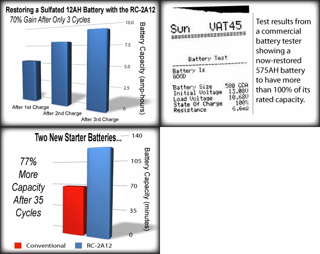
        This image shows REAL results that countless people have achieved with charging lead acid batteries - rejuvenating old batteries and having an increase in capacity on each charge cycle - same thing with new batteries to a lesser degree. Putting a 2A12 on a Harbor Freight 35Ah battery for one charge cycle will allow it to discharge about 39Ah on the very next cycle - increase in capacity whether you like it or not.


        Sincerely,
        Aaron Murakami

        Books & Videos https://emediapress.com
        Conference http://energyscienceconference.com
        RPX & MWO http://vril.io

        Comment


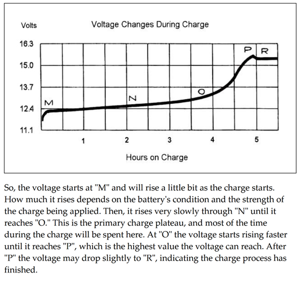
        • Graph.

          chart_lead1.jpg
          Attached Files

          Comment


          • Originally posted by axxelxavier View Post
            Just a quick update.
            As I told you, my test now it's using a booster, set on 14,7 volts on the output.
            Total time running, so far, is 6 hours, 43 min, and battery 3 seems to be charged faster, BUT, C20 rate are exceeded, because current draw on the input of the booster (which was in the beginning at 2 amps) now is on 2,62 Amp, and it's increasing (differential voltage on the input = 11,47 volts). On the output of the DC booster (going to the inverter), current draw is 1,74 amp.
            Not sure what to do, though. I think I am going to let the system to work for 2 more hours, and I am going to measure the current draw before stop it. If it will exceed 4 Amp, I think I am going to shut down my test. I cannot afford to kill a good battery...
            Now I am using a 150 watt, like the first image in the attachment, with no current limit.
            I have also a bigger one (1200 watt - second image in the attachment) which have an option to limit current... this should be better?
            Best regards,
            Teodor
            Connect the second boost convertor to battery 3, Bat 3 pos to boost2 in pos, bat 3 neg to boost2 in neg, boost2 out pos to bat 2 pos (top positive of series connected batteries 1 and 2). Slowly adjust the boost2 output to slow down the drain on the series batteries by recirculating current going to bat 3. At one point you can come to a balance where the voltages stay very steady for a long time.

            Comment


            • Originally posted by bistander View Post
              ... post truth, facts, evidence and proof.

              Simple, right?

              bi
              https://www.youtube.com/watch?v=MMzd40i8TfA
              “Advances are made by answering questions. Discoveries are made by questioning answers.”
              —Bernhard Haisch, Astrophysicist

              Comment


              • Originally posted by hherby View Post
                Connect the second boost convertor to battery 3, Bat 3 pos to boost2 in pos, bat 3 neg to boost2 in neg, boost2 out pos to bat 2 pos (top positive of series connected batteries 1 and 2). Slowly adjust the boost2 output to slow down the drain on the series batteries by recirculating current going to bat 3. At one point you can come to a balance where the voltages stay very steady for a long time.
                @hherby, thank you for your reply. I've done the modification to my setup, and now I'm watching the numbers...
                L.E. Booster 2 is quite hot... I hope it will resist to this treatment... :-)
                Best regards,
                Teodor
                Attached Files
                Last edited by axxelxavier; 01-29-2019, 06:46 PM.

                Comment


                • In the light.

                  In the light of overwhelming evidence from Aaron I’ll admit defeat on my
                  take on LA battery performance.
                  John.

                  Comment


                  • I'd like to replicate

                    Originally posted by axxelxavier View Post
                    Just a quick update.
                    As I told you, my test now it's using a booster, set on 14,7 volts on the output.
                    Total time running, so far, is 6 hours, 43 min, and battery 3 seems to be charged faster, BUT, C20 rate are exceeded, because current draw on the input of the booster (which was in the beginning at 2 amps) now is on 2,62 Amp, and it's increasing (differential voltage on the input = 11,47 volts). On the output of the DC booster (going to the inverter), current draw is 1,74 amp.
                    Not sure what to do, though. I think I am going to let the system to work for 2 more hours, and I am going to measure the current draw before stop it. If it will exceed 4 Amp, I think I am going to shut down my test. I cannot afford to kill a good battery...
                    Now I am using a 150 watt, like the first image in the attachment, with no current limit.
                    I have also a bigger one (1200 watt - second image in the attachment) which have an option to limit current... this should be better?
                    Best regards,
                    Teodor
                    Hi Teodor,

                    Did you get more data? Also, please post or refer to a circuit diagram. I am considering doing the test here.

                    Thanks,

                    bi

                    Comment


                    • topping charge

                      Originally posted by Iamnuts View Post
                      chart_lead1.jpg
                      It's very simple - I agree that chart is accurate, but only shows what happens when a topping charge is not attained. Why limit your possibilities to only that, which has been thoroughly conditioned into the mass mindset? That doesn't apply to what I told you, however. Again, any conventional charger pushing batteries to 13.8-14.8 will have a decline in capacity over time because on each charge cycle, there is still sulfation left on the plates.

                      That is the entire point to what I was telling you.

                      Here is the pdf with the chart for anyone to see - there is a lot of good info in there on lead acid charging chemistry: http://freesolarsecrets.com/solarsecrets.pdf

                      This is the most important chart ever made for lead acid battery science, in my opinion.


                      You must charge the battery until you get the voltage dip transition from P to R. When you do, you have reversed the chemistry to like-new condition. The dip is a drop in impedance as I said, the final layers of sulfation dissolved into the solution. If you do this on every charge cycle, the battery life cycle is theoretically INFINITE. If you have a solar setup with battery backup, the batteries can outlast the solar panels, which are expected to last 20-25 years, if the batteries were able to get pushed to the topping charge.

                      That chart is 100 years old - that is how long this has been known but the lead acid battery industry has quietly ignored this because they're in the business of selling batteries.

                      About 1-2 years ago, I met with a Linear Technology rep and we were talking about batteries. He used to be in the nicad industry and he said that is very well known that if you charge nicads without experiencing the dip, you will wind up damaging the batteries - yet, nobody seems to know this is exactly what lead acid batteries need as well.

                      If the batteries are AMG or gel cells, then 14.6-14.8 is the limit or you will dry them out - they also display the same voltage drop when they are truly topped out.


                      John, it would behoove you to understand this because if you failed in achieving results experimenting with the methods Bedini made popular, then you weren't applying all the information. I like John Koorn's rule of thumb if I recall it correctly - with a Bedini type system, 1 watt per 1 Ah is about what you need to do it right. So a single coil SG with 7-8 power windings will be roughly a 20-25 watt machine so is only good for getting a battery that is 20-25 Ah pushed to 15.1-15.3 volts.


                      I've seen the results go up in a very non-linear fashion. With Bedini's 10-coiler, that would be around a 200 watt machine - however, it could fully charge a 1200 Ah cell phone tower battery bank being run on an identical 1200 Ah battery bank. Each battery in the string was 2 volts 1200 Ah as far as what I can recall. And, when the output bank was charged, Peter discharged that output bank and got 10 times more than what left the input battery. That is a COP of 10.0 - that is some serious "overunity", but most people can't afford those banks. I wouldn't want them because they're a pain to handle. The reason is because of the ultra-low impedance on a bank that big. With the radiant impulses, any resistance dissipates it so with a large battery bank like that, it sucks it up like a vacuum. The round trip efficiency is irrelevant with these methods because what you get out of the battery is related, but is absolutely NOT directly proportional to what went in into the battery. The chemistry converts that radiant into charge separation and the amount of charge separation is clearly INDEPENDENT of the amount of electricity that went into the battery because it is an open system. The coils on the SG are open and the battery is also part of the open system. I don't know if I agree exactly with all the subtle nuances of Bearden's Negative Resistor explanation of the batteries being charged in this method, but the output battery definitely is put into a negative resistor mode.


                      Every time you have an impulse (sharp gradient), you are polarizing the aether at the coordinates in space where the terminals are, dipole or each bit of chemical charge separation. The aether then polarizes and condenses and moves into the circuit at those points meaning with the impulses, you are causing those points to become locations where environmental source potential enters the system. That polarized aether is the emf (electromotive force), which moves from positive to neutral and that causes electrons from the circuit to start moving in the opposite direction, which is the source of current - the copper wire, not magical charge that people think is stored in the battery.


                      This is why it is important to use as big of batteries as you can and is why most people have never seen anything unusual with small batteries. Dave here has mentioned big batteries many times and this is one of the main reason why - the lower the impedance, the more the battery chemistry will convert radiant to charge separation. You don't need 1200 Ah batteries.


                      I use 35Ah AMGs all the time for just testing things out and getting a feel for what I'm doing in my experiments. 100Ah at minimum is more time-worthy if you're looking for something interesting but I like my T-105s the best - those are 6v 225Ah batteries.
                      Last edited by Aaron; 01-29-2019, 11:54 PM.
                      Sincerely,
                      Aaron Murakami

                      Books & Videos https://emediapress.com
                      Conference http://energyscienceconference.com
                      RPX & MWO http://vril.io

                      Comment


                      • Battery Chargers???

                        Aaron,
                        With John's passing, is anyone manufacturing battery chargers based on his tech. I mean besides "you know who"?
                        “Advances are made by answering questions. Discoveries are made by questioning answers.”
                        —Bernhard Haisch, Astrophysicist

                        Comment


                        • Bedini's chargers/rejuvenators

                          Originally posted by Turion View Post
                          Aaron,
                          With John's passing, is anyone manufacturing battery chargers based on his tech. I mean besides "you know who"?
                          Short answer: Tom & Eric are making some solar charge controllers available and I've been testing some prototypes based on John's circuits that I'm putting into production soon.

                          Long answer: see below...

                          Tom & Eric I think have a couple solar charge controllers. Those are straight linear current regulator chargers so are not the best for rejuvenating old batteries but are good for keeping good batteries in good condition.

                          Soon, I'll be putting a 5 amp 12 volt solar charge controller back into production - actually, John only made one of those for me for to test, but it will be produced instead of the 3 amp 12v one, which was very popular. It is also a linear current regulator circuit.

                          If you get a constant current constant voltage adjustable dc power supply - you can set it to charge up to 15.1-15.3 for flooded cell batteries - just short the leads and adjust how much current you want it to max out at and when hooking it to a battery, it will for the most part act just the same. Just with the solar charge controllers, they can always receive solar input easily.

                          I've been testing one of John's prototypes that is more efficient than the older charge controllers (Solar Trackers) - still linear current regulator circuit, but more efficient. He considered it to be the best one he ever designed but never had a chance to put it into production. I'm waiting for some of the components so I can build a few more prototypes for testing. This one will obsolete all linear current chargers that he produced in the past.

                          Any of these solar circuits can of course be operated with a power supply instead of panels - like the one described above to mimic a solar panel for testing.

                          For rejuvenation of older batteries, the only charger John came out with that did that with inductive discharges (spikes) was the original Generation 1 - 2A12 - 2 amp 12 volt. It was short lived because the batteries charged or rejuvenated that way long enough didn't like to get charged with normal straight current chargers anymore. All 2A12 models after that went to cap discharge.

                          The last model (5th generation) 2A12 that was released was the EX or Extreme version, which was the best. It was actually identical to the 3rd generation model. The 4th generation was less aggressive and discharged a cap about half as fast - still excellent but the 5th generation was a reintroduction of the 3rd generation because it was stronger. Magically, after John died, the pic chip source code for that model disappeared. I might just put the 4th generation one back into production - still an excellent unit and nothing else touched it for what it was compared to anything on the market.

                          I have also been experimenting with some of the old Tesla Switch Solar Amplifier circuits prototypes. I may put those back into production as well and they are also excellent rejuvenators. The charged the caps in parallel and discharged in series.

                          First one I'll put back into production will be the S5A12 solar charge controller. Second will be either the 2A12 Generation 4 model or the Tesla Switch Solar Amplifier or the linear current one that is the most efficient one that John never put into production. Anyway, the 2nd one to be put in production will be one of those 3 - haven't decided yet.

                          Other than these future plans, nobody is producing anything worth mentioning in my opinion.
                          Last edited by Aaron; 01-30-2019, 07:34 AM.
                          Sincerely,
                          Aaron Murakami

                          Books & Videos https://emediapress.com
                          Conference http://energyscienceconference.com
                          RPX & MWO http://vril.io

                          Comment


                          • Originally posted by bistander View Post
                            Hi Teodor,
                            Did you get more data? Also, please post or refer to a circuit diagram. I am considering doing the test here. Thanks,
                            bi
                            @Bi,
                            I have data only for the first run of the 3BGS setup with booster, which last only 11,27 hours, until differential voltage drop below inverter low voltage limit (9,6 volt).
                            Second run is not complete, and I added also a second booster, for recovering some energy in the primaries. The results looks so far promising, but, I believe now the load it's too big for the system, so I may drop one led bulb, to see if I can balance the system.
                            In attachments, you will find also the schematics with one booster and with two boosters, I hope they are clear enough.
                            Best regards,
                            Teodor.
                            Attached Files

                            Comment


                            • Thanks

                              Thanks, I can work with those diagrams.

                              Was the 2.070 Amperes in the baseline (test without boost converter) measured at the input to the inverter?

                              Regards,

                              bi

                              Comment


                              • @Bi,
                                Yes, this value was on my first setup, at the input on the inverter, without booster, using only a 300 watt inverter (200 mA idle current draw) and 3 LED bulbs as load (two 7 watt Led bulb + one 8 watt led bulb).
                                With booster set on 14,7 volts on the output (inverter), current draw raised quite fast to almost 2,8 Amp, as you can see in my latest diagram.
                                Now, I've removed from load one led bulb (7 watt), so current draw now fit in C20 discharge rate, and I have also hooked the second booster back to primaries.
                                I am just curious to see how much will last this setup.
                                L.E. Just a quick update. I've notice something interesting: yesterday I was using for a time the second booster, and today, after almost 18 resting hours, batteries showed almost the same voltage as before rest...
                                In my previous setups, without the second booster, the voltages from all three batteries has changed significantly after a long resting - both bats from primaries gain some volts, and the charged batteries usually lose some volts....
                                Best regards,
                                Teodor
                                Last edited by axxelxavier; 01-30-2019, 05:28 PM.

                                Comment

                                Working...
                                X