Announcement

Collapse
No announcement yet.

3 Battery Generating System

Collapse
This topic is closed.
X
X
 
  • Filter
  • Time
  • Show
Clear All
new posts

  • ehsanco1062,

    Sorry I have kinda been off in my own little world. Just got back from nine days in the Hawaiian Islands, and trying to get the house and yard back in shape after being gone so long.

    I do have my setup all wired up (as of last night) and will be testing it today to see how fast the cap fills up. Then will be running it to see how it performs. That whole process will begin in about two and a half hours. Have some things to do first that I promised the wife I'd get done before I lost myself in the basement for the rest of the day. She knows me too well. Once I get down there it takes a forklift to get me out. Probably because I weigh so much!

    Dave
    Last edited by Turion; 07-20-2012, 04:52 PM.
    “Advances are made by answering questions. Discoveries are made by questioning answers.”
    —Bernhard Haisch, Astrophysicist

    Comment


    • ehsanco1062,

      Got it wired and did some testing. Matt says we need to get a .1uf high voltage cap (Radio Shack has some that will work) connected across drain and source on the series fett (the one connected between the two batteries) just to make sure it doesn't blow. So I will pick one up first thing tomorrow. Will post some results and pictures once I have that cap in place and feel more secure about doing a long run. It IS working though. Now to see if it will run a load and still keep all the batteries charged. I am going to find a bridge rectifier so I can run a 12 volt load and charge a battery at the same time, but until then I will run my 24 volt load and see if it will run the other two motors as generators. Should be interesting. Tomorrow i will have results for you all and some video posted on YouTube.

      Dave
      “Advances are made by answering questions. Discoveries are made by questioning answers.”
      —Bernhard Haisch, Astrophysicist

      Comment


      • Originally posted by ehsanco1062 View Post
        Hi all

        I have receive my order from Digikey today so I have all the parts to start with the scaler.
        I am preparing my self for the soldering to get the board ready so as soon as I complete the board I will go to wind the transformer .
        I don't see any one posting here I mean David what's up how is your setup going ? Any result?

        Ehsan
        Hey Ehsan

        I had an after thought while talking to David on the phone. You may wanna put a 500v .1uf Non Polarized ceramic cap across the Drain and Source of your serial Fet. This should protect it in the event the timing is quicker than anticipated.

        Also Have I given you the code for the Stamp or what ever your using?

        Let me know and I'll post it with and explanation.

        David is getting ready to start tuning his so I'll know better tomorrow how it works out.

        Cheers
        Matt

        Comment


        • Originally posted by Turion View Post
          ehsanco1062,

          Got it wired and did some testing. Matt says we need to get a .1uf high voltage cap (Radio Shack has some that will work) connected across drain and source on the series fett (the one connected between the two batteries) just to make sure it doesn't blow. So I will pick one up first thing tomorrow. Will post some results and pictures once I have that cap in place and feel more secure about doing a long run. It IS working though. Now to see if it will run a load and still keep all the batteries charged. I am going to find a bridge rectifier so I can run a 12 volt load and charge a battery at the same time, but until then I will run my 24 volt load and see if it will run the other two motors as generators. Should be interesting. Tomorrow i will have results for you all and some video posted on YouTube.

          Dave
          Hi Dave

          Thank you fot quick response it seems that you almost done thats realy encouraging but this cap 0.1 will make a delay to me ordering this wil cost me two weeks because I will never find such a parts in Sweden or in Europe its only in USA .
          Can't wait to see the result and video please

          Good luck

          Ehsan
          Take the wisdom even from the mouths of the insane
          Comment


          • Originally posted by Matthew Jones View Post
            Hey Ehsan

            I had an after thought while talking to David on the phone. You may wanna put a 500v .1uf Non Polarized ceramic cap across the Drain and Source of your serial Fet. This should protect it in the event the timing is quicker than anticipated.

            Also Have I given you the code for the Stamp or what ever your using?

            Let me know and I'll post it with and explanation.

            David is getting ready to start tuning his so I'll know better tomorrow how it works out.

            Cheers
            Matt
            Hi Matt

            Thank you Matt ,
            I am using basic stamp 2 and you didn't gave the code yet you said that you will give me the code when I will start and I will start today but a two weeks delay to get the 0.1 cap,

            Ehsan
            Take the wisdom even from the mouths of the insane
            Comment


            • Hi Matt

              I found this cap C100U630M - 0.1uF 630V Mylar Capacitors I can get it in one week does it work?

              Ehsan
              Take the wisdom even from the mouths of the insane
              Comment


              • Ya that will work. Sorry about that. But the advantage to having it is it protects your Fet.

                Matt

                Comment


                • Thank you Matt
                  I have just complete soldering my board ,it wasn't
                  So difficult thank to you and with the help of my new soldering iron
                  Station so I just need to wind my transformer to start testing.

                  Good luck

                  Ehsan
                  Take the wisdom even from the mouths of the insane
                  Comment


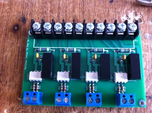
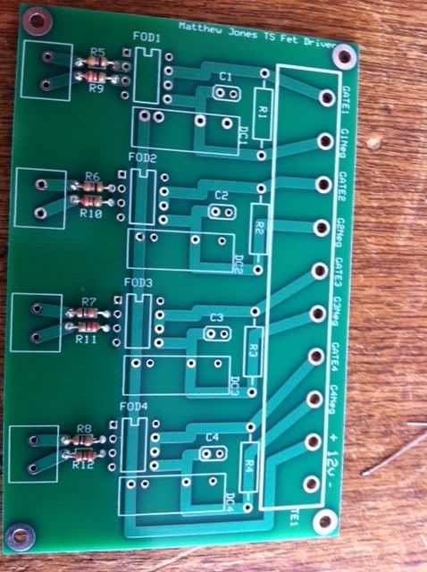
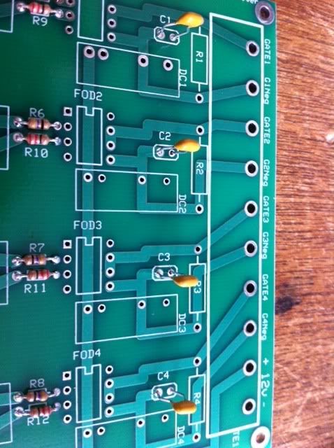
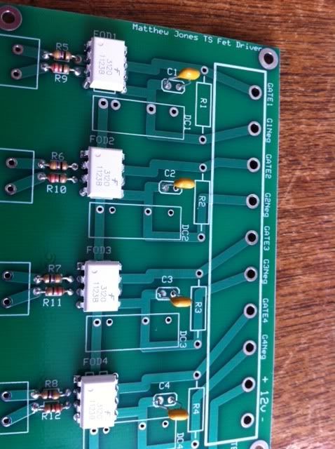
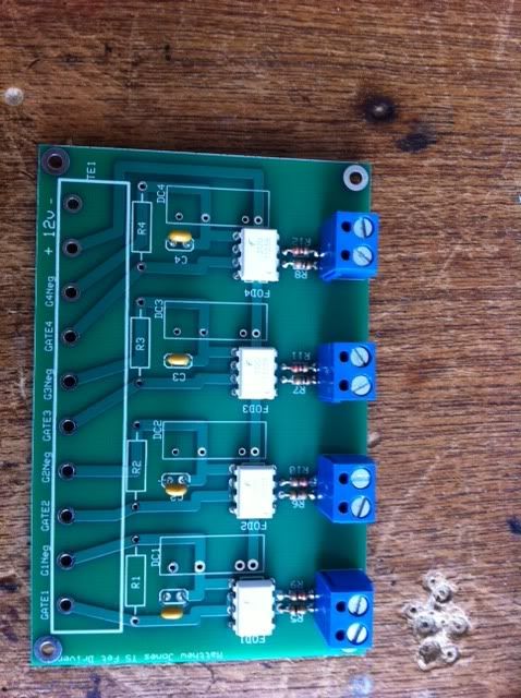
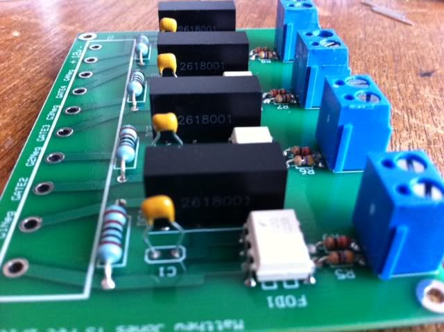
                  • Here is a step by step soldering the PCB for the scalar charger:


                    1. Soldering resistors 47, 22 ohm


                    2. Soldering 4 capacitors 0.1 mf 50v


                    3. Soldering OPTOCOUPLER GATE DRV 2.5A 8-DIP


                    4. Soldering TERM BLOCK 5.08MM VERT 2POS PCB


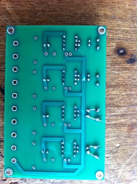
                    5.Here I had to enlarge the hole because these terminals a little bit wider than the holes and when I did that I found that there is no connection between the terminal and the resistors so I make the connections by soldering as you can see in the picture below .


                    6. Soldering DC-DC Converter 12v-15v


                    7. Close picture to the co\DC-DC converter


                    8. Finally here is the board with the entire component


                    Good luck
                    Ehsan
                    Last edited by ehsanco1062; 06-15-2012, 09:11 AM.
                    Take the wisdom even from the mouths of the insane

                    Comment


                    • Hey

                      I completely did not add those traces. I apologize. I am glad you had enough sense to figure it out.

                      Have you had a chance to test the board and make sure everything is working?

                      Matt

                      Comment


                      • Originally posted by Matthew Jones View Post
                        Hey

                        I completely did not add those traces. I apologize. I am glad you had enough sense to figure it out.

                        Have you had a chance to test the board and make sure everything is working?

                        Matt
                        Hi Matt

                        No I didn't test the board except that test I did to see if there is connection between the resisters and the terminal after I enlarge the hole for the terminal
                        But do you want me to do specific test ?because I don't have the experience to do test with power or I will blow the board which is cost me with the components 400$!!! And I am not familiar with the optocoupler or the dc-dc converter and I don't know what to do just waiting to wind the transformer while I wil get the 0.1mf 630v.
                        So if you want me to do any test please tell me what to do and I will do it .

                        Ehsan
                        Last edited by ehsanco1062; 06-16-2012, 12:06 AM.
                        Take the wisdom even from the mouths of the insane
                        Comment


                        • I know all about blowing up boards! LOL One down, two to go!! have been running tests for the last hour or so since Matt helped me to correct a number of errors plus the connections on the board that needed a wire soldered on to complete them. My issues with the board were NOT the same as what you experienced. Or at least I THINK the issues were different. Where the resister connects to the 3120 there was no trace, and since it is such a small gap, I bent the end of the resister over and soldered it to the 3120 to make sure there was a complete circuit, which eliminated the NEED for a trace there. They are so close you could almost solder them together if you are careful (if you have already cut them off) My terminals also did not want to fit into the holes, but I solved that problem by laying the board on a piece of soft wood, placing a block of wood on the terminal, and tapping on it gently until it went in. It was a tight fit, but it went. Once they were in there was a connection to the resister, I checked with a meter. SO I didn't have any soldering to do there. I would advise you to check the back of your board to see if all the resisters connect to the 3120's. There was a trace on the first one, but not the rest.

                          I had my setup putting out 50 volts to the caps on a setting of SW10 pulse 100. It would hit 50 volts in the cap in a split second. I have yet to do a long run. Been cleaning up the wiring maze and making sure everything is tight and won't vibrate lose on a long run. Also I have had ANOTHER problem....After charging and dumping the cap several times where I felt like it was at 48-50 volts (my analogue meter isn't the best, but on the 50 volt AC scale, it was pegged to the right) I decided I was ready to run the program for a long run. Then I changed my mind and reloaded the test program. At that point it didn't work like it had been. The transformer is only staying on for a split second, and only putting out about 6 volts to the cap. So Matt will have to babysit me some more until THAT is fixed. He has been really patient working with me to get through this, and when it's up and really running, I promise...videos!! Oh, and I owe Matt a beer, or two...or 50.

                          Dave
                          Last edited by Turion; 06-16-2012, 01:27 AM.
                          “Advances are made by answering questions. Discoveries are made by questioning answers.”
                          —Bernhard Haisch, Astrophysicist

                          Comment


                          • Hey Dave,

                            This should give you a warm fuzzy feeling - knowing you are barking
                            up the right tree ->>>>


                            http://www.energeticforum.com/renewa...tml#post197937


                            Penno

                            Comment


                            • A Run Down

                              Most of ya'll are about to have this thing put together. So I wanted to make post that is up to date on everything.
                              First, I screwed the PCB board on the switch driver. I left some traces blank and you'll have to make jumpers. The traces should have been on the top side but you can jump on the bottom.
                              The circled marks are the traces missing.


                              So just jump the tail from the resistor over to the 3120 pins and you'll be fine.

                              @Ehsan you might have the wrong pins soldered, not sure but double check yourself.

                              It was rookie mistake and I apologize, again.

                              I'll refer to this schematic for now.

                              Now one thing Dave has run across and we need to address at least in the short term. He has burned his Serial switch up on a very short run indicating to me that the battery is not absorbing the transient produced on L1 and L4. Dave also is running a 3KVA transformer body so his experience may not emulate anybody else's. But in the short term because some of you got alot tied up financial I would unhook those leads back to the battery. Its going to change the initial performance but we will address it immediatly and see what we have to do to protect that FET.

                              We have already tried hooking a 500v+ .1 uf cap between the drain and source and he still had an issue.

                              We'll get back to this soon.


                              Also one thing I haven't pointed out is for testing purposes use a seperate battery to drive the STAMP and the DRIVER BOARD. This will protect both of them from damage.
                              Later we will modify the circuit to accommodate both being powered off the system.


                              CODE:

                              This first piece is a test to find out how long it takes to fill up your caps. We'll need this in the bigger piece of code.
                              Both pieces of code are for the STAMP BS2e

                              Code:
                              ' Drive Serial switch
                              ' {$STAMP BS2}
                              ' {$PBASIC 2.5}
                              
                              SW VAR Word 'Serial Switch count
                              SW = 0
                              
                              DO UNTIL SW = 1 ' Change the value of I to increase the number loops until caps hit 48 - 52 volt.
                                PULSOUT 0, 10 ' ' pulsout time (10) might be too fast you can slow it down as low as 1800 (60hz)
                                PULSOUT 10,10 ' Just somthing to cause a pause on pin 0. Adjust as needed with above pulsout command
                                SW = (SW + 1)
                              LOOP
                              So I'll give you the run through. First is the variable SW (Switch) we use to count how many time we switch. Initially we set it to 0. Currently it is set to 1. So we'll end up making 1 pulse on our serial switch F1 (refer to the schematic)
                              This pulse will be on Pin 0 of the Stamp and will turn on for 200 nano seconds. 1 Unit in a pulse out command is worth 2 nano seconds.

                              So want to start out adjusting the "SW" count. The point of the test is to see how fast the caps fill up to 48-52 volt range.

                              DO UNTIL SW = 1 all the way 50. You can change it to anything from 1 to 50. You probably wont need to go to 50 but you can.
                              If you get to 10 I would start adjust the the pulse width.

                              PULSOUT 0, 10

                              10 can go as high as 1800 hundred. This will put you at 60 hertz or so. Most likely you won't need to go over 500 but the option is available to you.

                              Make sure to adjust the Second PulsOut command equally. All it does is pause the system as we do not use Pin 10 for anything. This gives you somewhat of a 50% percent duty cycle. The stamp though adds a small amount of time going through a DO....LOOP. So you might adjust the second pulsout command differently to try to get 50%.
                              You'll see what I mean when and if you look on your scope to adjust your pulse width.

                              So once you have found the amount of time and pulse width to fill caps up to 48 -53 volt you need to make note of the two variable you change we will use them in the next piece of code.

                              I'll put that in the next post.

                              Matt
                              Last edited by Matthew Jones; 06-16-2012, 12:01 PM.

                              Comment


                              • Alright so I am going to get into this next piece of code but I gotta start warning you.
                                I am not responsible for any damage or injury that occurs from from running this system. It is entirely YOUR choice to follow the instruction and safety precautions outline in the following article. Experiment at your own risk.

                                One thing you have to understand with this thing is the type of interaction we are going to perform on this battery. We are not going to let it discharge although we are going to initially pull power from it, we are going to force it to recharge between pulses. This cause the ions in the battery to rapidly vibrate and they do not like to be in that state. It might produce heat and gassing while we are doing this.
                                So close monitoring of you fluid levels is a must.
                                When you get this code up and running for the first time make sure to have fan near by to remove any possible gassing and make sure to POP the TOPS on the battery so you can see if they are rapidly boiling.

                                Do this until you are comfortable that the batteries are interacting safely with the circuit.

                                MAKE SURE TO USE ONLY LEAD ACID BATTERIES WITH FLUID. NO AGM'S OR GEL CELLS.

                                Code:
                                ' Drive Scalar Charger Complete
                                ' {$STAMP BS2}
                                ' {$PBASIC 2.5}
                                
                                SW VAR Word 'Serial Switch count
                                CD VAR Word 'Cap Dump Count
                                DO  'Main Loop
                                  CD = 0  'Set CapDump (CD) to 0
                                  DO UNTIL CD = 2  'Loop the Cap Dump count
                                    SW = 0  'Set the count for Serial Switching
                                    DO UNTIL SW = 1 ' 1 for now but after test this will change!!!!!!!
                                      PULSOUT 0, 10 ' 10 for now but after test this will change!!!!!!!
                                      PULSOUT 10,10 ' Just somthing to cause a pause on pin 0. Adjust as needed with above pulsout command
                                      SW = (SW + 1) 'Incriment the serial Count
                                    LOOP 'Loop Back unless we are done with the serial switch
                                    CD = CD + 1  ' Incriment the Cap Dump Count
                                      IF CD = 1 THEN   'Check the COUNT so we can switch between caps this should fire cap 1
                                        HIGH 1         ' Turn on the Cap Dump Fet for cap 1
                                        PULSOUT 0, 10  '10 for now but should be the same as SW Pulsout!!!!!!!!! This turns the serial on and allows the cap to dump
                                        PAUSE 1         'Pause it for a 1/1000 of second
                                        LOW 1           'Turn off the cap switch
                                      ELSEIF CD = 2 THEN 'Check the COUNT so we can switch between caps this should fire cap 2
                                        HIGH 2
                                        PULSOUT 0, 10
                                        PAUSE 1
                                        LOW 2
                                      ENDIF  ' Gotta end our tests
                                  LOOP ' loop back up to increment count CD will never go higher than 2 or it will reset to zero
                                LOOP 'End of main loop
                                Now you have to read this thing through a few times.

                                We have to take the numbers we found in the test and change those things in this code.
                                First look for "DO UNTIL SW = 1" change that to the number we came up with in the test.
                                Now we have 4 pulse out commands. The first 2 are just like the test. And they need to reflect the the same numbers you used in the test.
                                The second 2 have NO PAUSE via a pulse out command so you just need to reflect the the number in the the FIRST pulsout command.

                                Read the comments and you we'll see how its supposed to work.

                                Now basically this is what is going to happen step by step.


                                (We are going to skip this first part for now, until the issue is resolved)
                                Now every time we pulse we also have a winding in the inductor that pulses back to the battery on the 12 volt level. This winding creates is charged to 24 volt and dumps directly to the battery through diode to create the correct polarity.
                                Now you have to understand that a difference in potential will create a rise in current. So we pulse the primary with 24 volt (Maybe 5 amp) on a single winding. This pulse then transfers over and a reduced current to the secondaries on L1 and L4 to about 23 volt. Immediately the 23 volt travel down to the 12 volt battery. This will cause a 5 +- amp current flow to each 12 volt battery.
                                So we have now replaced the energy we took from the battery. But the battery is in discharge mode so it reasonable to assume that only 15% percent of the power we put back will be available to the battery in the future. The rest will become a skin charge. This skin charge will be available immediately on the next pulse.
                                But because turned the inductor ON then OFF rapidly the transient will show up on the OFF time. This also will produce energy that in turn immedialty returns back to the battery. At the same time this transient will replicate itself on all windings equally. So some of the power will go to the caps and some to the load.

                                You are going to drive the serial switch for given amount of pulse and a certain pulse width.
                                The 2 caps are going to fill up.
                                The we will dump one them at the same time we turn on the serial switch. This will a cause a surge in the system that will lower the impedance in the battery to further allow us to absorb all returned energy.
                                Then we will pulse some more and dump the other cap and create another surge.

                                We should realistically dump the caps at least 2 times a second but that vary from system to system based on how much transient energy is produced.

                                Now this is the big one.

                                The 2 primary windings used are both legs of the power. Positive and Negative driving in the same direction across the transformer. Both windings creating one field.
                                The collapse of this field does not produce the typical transient. It produces a Scalar as defined by Tom Bearden. A spike going in each direction of polarity equally in the same time frame.

                                This type of transient is very different and has alot of gain in it when collapsed across an EI core.

                                We are also sending that power either to load or to another potential like a battery. 50 percent of everything you send through this can be collected on the back end. At the time you are using the power the transients (Scalar) created are replicating themselves equally across all the windings.

                                8 Windings total and 6 used for return power you should at some point stop discharging the power from the battery.

                                Now it won't happen immediately. Tuning and load are all going to effect the behaviors of this circuit. But it will work. I have already seen enough to know.

                                Your load should start out small and be increased as tuning gets better. The batteries will almost never perform to par right away. You will need to use the same batteries on this system to create a pattern in the battery that is tuned.

                                Ok well thats about all I can think of to give you at this point. Please post question here is you have any.

                                If you find anything wrong Make a real big note of it so we can get it solve and I will start working on the FET issue and we'll get that resolved.

                                Good luck
                                Matt

                                Comment

                                Working...
                                X