 Tweet
Tweet
ehsanco1062,
Sorry I have kinda been off in my own little world. Just got back from nine days in the Hawaiian Islands, and trying to get the house and yard back in shape after being gone so long.
I do have my setup all wired up (as of last night) and will be testing it today to see how fast the cap fills up. Then will be running it to see how it performs. That whole process will begin in about two and a half hours. Have some things to do first that I promised the wife I'd get done before I lost myself in the basement for the rest of the day. She knows me too well. Once I get down there it takes a forklift to get me out. Probably because I weigh so much!
Dave
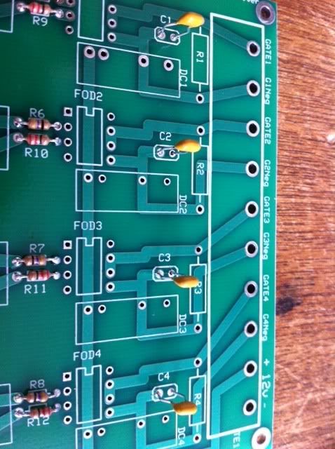
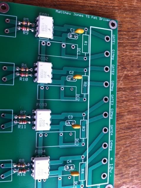
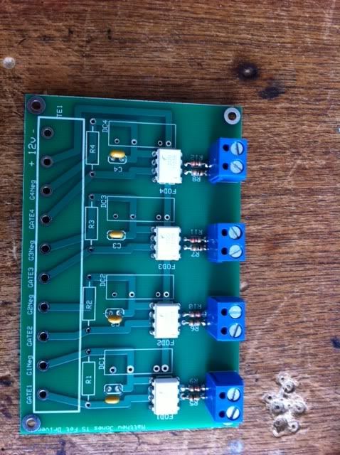
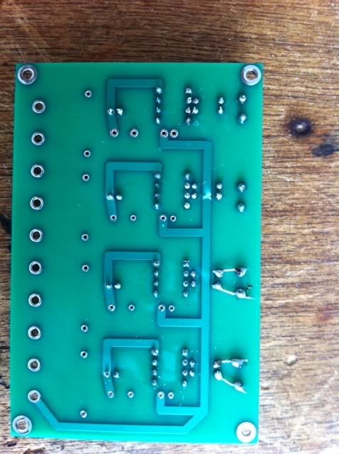
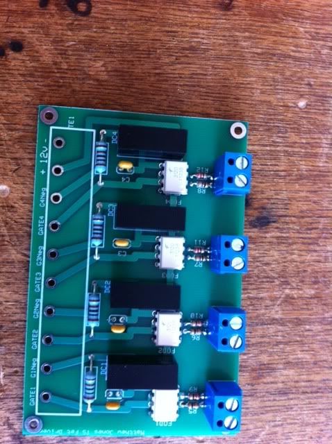
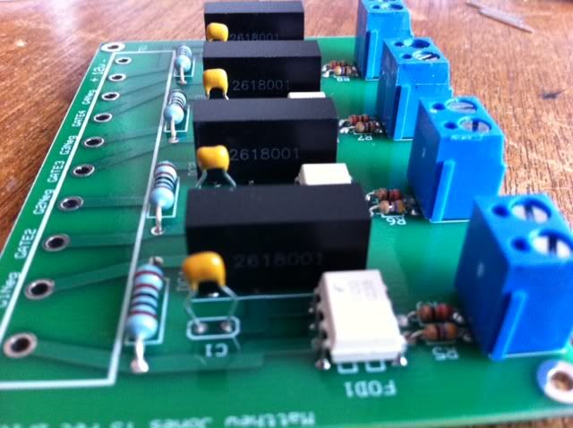
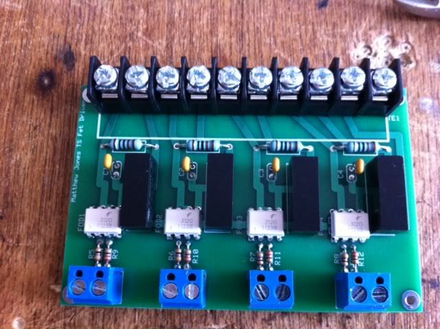
 to get the board ready so as soon as I complete the board I will go to wind the transformer .
 Take the wisdom even from the mouths of the insane
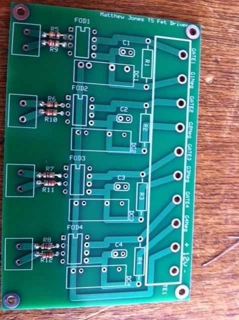

Comment