Pieces of the puzzle
Just returned from Lowe's store with precut 3/4" x 14" x14" plywood 4 pieces. Also some pvc 3" unions to hold the coils in place. I will use wooden dowels with pvc pipe as spacers and construct the holders so they can be removed to add coils as they are made. Not sure of the rigidity/strength of this design, only a build will reveal that.
wantomake
-
Arduino switching
Good coffee sippin to All,
Did some more Arduino switching setup yesterday. This is the way I plan to switch the five battery positions around in the 3BGS setup.
I'm a noobie to this C++ and Arduino workings. I want to use the 8-channel relay module to switch power to a separate set heavy duty relays for the battery banks.
At this stage I'm currently learning Arduino and building the generator/motor as per Dave's video. As time and life allows.
Just posting to give update and encourage any builders or interested out there,
wantomakeLeave a comment:
-
Separate spools
Ken,
I�ll be using different spools per strand. Will wind each spool separately from larger purchased spool. The winder has a counter so can wind each spool exact feet as I need.
Yea my first windmill worked ok. But made the props out of pvc pipe a big no-no. The high winds,a storm actually, broke them and one stuck in the ground like an arrow. Saw the whole thing from my shop. Never build cheap windmill again.
wantomakeLeave a comment:
-
Hi Wantomake,
I hope that my input here is acceptable.
10+ years ago, I built homemade 3 phase windmills. My first windmill built from scratch, I built by winding coils. I really didn't understand what I was doing very well at the time, and being off grid, I needed power quickly. With limited funding, I didn't have the correct size of wire that the plans called for. I did however have 28gauge wire and reading about lits wire being good for alternative energy projects I decided to use the wire I had and make my own lits wire to match the gauge the plans called for.
I had one large spool of 28gauge wire, so I pulled off 100 feet of wire, cut the end and left that strand laying straight. I then repeated that process 49 more times. This was a difficult process for me, as the wires wanted to get tangled, or kinked, and while winding the coils, behaved like herding cats.
My coil winder I built from a 500 rpm 24 V motor running on 12 volts or even 6 volts from a battery charger into an old washer worm gear reduction box. On the end of the reduction box I built a special coil former with removable sides to keep the coil in the correct shape (a teardrop shape) and thickness.
From my experience and studying, a hand winder will cause your coils to be tight on one side and loose on the other because your arm has greater strength pulling than pushing. Whereas with the motor you can maintain equal tension on the entire circle.
Your set up sounds like you will have spools for each strand. That set up would be prohibitively expensive not to mention a construction nightmare for me. I don't know whether you are going to buy one spool of wire and de-spool enough wire for each strand onto a separate spool, or buy one spool of wire for each strand.
Ultimately this version of the three phase windmill was a failure as vibration at the connection points caused the small strands to break. Furthermore lits wire achieves gains with high-frequency, and my windmill would only operate in low hertz, therefore no gains were realized. Even though the windmill functioned, it's output was not up to specification, so the next windmill had the correct gauge of wire and worked much better.
Your coil winder description sounds good for a few wires. If you're going to do very many strands like I did, you'll have to stack threaded rods vertically as well.
However you decide to do it, I'm cheering from the sidelines here. I expect you to receive inspiration on what to do.
KenLast edited by kenssurplus; 03-28-2018, 06:43 PM.Leave a comment:
-
DIY machines to wind a coil
To ALL,
Ordered wire, spools, coil winding machine with counter this week.
Trying to build a multi-filar coil winding setup before all the parts get here. Thinking to use threaded rods lined up across on a board side-by-side. Place a large washer, the spool, washer, lite spring, washer, then nut. The spring to keep the magnet wire taught as all wires are pulled through a plastic donut guide then onto the main coil spool mounted on the mechanical/hand coil winding machine. I know pictures would be better but planning before building works best.
Any ideas are welcome. If anything I'm approachable and will discuss ideas.
Thanks,
wantomakeLeave a comment:
-
SG with gen coil
At least it was disclosed in the book - and is probably 10 strand and not 12.Originally posted by BroMikey View Post
This machine was never a self runner but comes very close to breaking even (electrically) - we haven't even added mechanical, which you can see if you do the leather strap, spring scales method with a pulley. If you do, attraction mode can be around 25% or more in equivalent electricity so it is a bit over 1.0 COP. However, I only brought up the SG because of the gen coil that is related to this current topic.
What is very interesting about it is that at x draw running on normal mode, the cap bank is discharging y joule seconds per dump at a certain speed.
When switching it to generator mode, the input draw only increased about 50%, but the cap discharge is now discharging twice as fast so the cap output doubled in joule seconds for the same time. And this doesn't even use the gen coil output.Last edited by Aaron; 03-28-2018, 10:08 AM.Leave a comment:
-
Yes I see what you mean. This is a design we heard from MullerOriginally posted by jettis View Post
but anyone sitting down with a wheel of magnets searching for
the best low cogging alignment for gen coils might come up with
something similar.
The part that I like is the mention of the special circuitry where OU
can be had (it doesn't say "Special circuits") by other means than
what our discussion has so far been centered around.
Others steps beyond the 3 batt sys never end it would appear.
I see Thane using the parallel wound series connected coils right off
bat but not Muller, and then like Muller and others did, at the same time,
collect up (with special circuits) the inductive spike and throw THAT
energy back to the batteries ALSO.
So that is 2 sources of energy circulating in the system used to recharge
the drive energy and does not take away from the normal run processes
that we all know. You know battery to motor and the battery goes
down and goes down even faster if you try to tap in.
I saw John put an encoder wheel on his pancake generators off the
big ole giant wheels almost hitting the ceiling. Such drama.
Gonna miss John.
John was playing with collecting back also.Last edited by BroMikey; 03-27-2018, 07:44 PM.Leave a comment:
-
FYI Here is patent number https://docs.google.com/viewer?url=p.../US5514923.pdf
We have seen this design (5,514,923) in Muller, John Bedini’s exterior three coils on the Ferris wheel and elsewhere on this forum and Energy Science Forums etc.
I do not know if Muller ever patented his device but it appears that this Patent Number: 5,514,923 sure seems to be a direct representation of what Muller and a partial of what John Bedini displayed.
Here is the abstract and summary of the device that is relevant to this topic currently being discussed. Figure 3 from the the patent 5,514,923 shows the three coil offset embodiment clearly, just as in the three large outside coils on John’s ferris wheel.
Anyway here is the...
ABSTRACT A high efficiency multi-phasic type DC motor incorporating brushless electronic switching to phase the attractive and repulsive forces between the permanent magnets in the rotor and wire wound air core coils in the stator. The unequal number of magnets and coils provides a designed imbalance, so that proper energization induces rotation and torque in the motor's dual flywheel rotor. Electronic switching collects inductive kickback and back emf simultaneously during the motor phase and in addition, disconnects the attraction and repulsion phases during regenerative braking, etc. and directs all this generated power back to the power pack where it is stored in batteries and capacitors. The rechargeable batteries and capacitors in the power pack are the source of operating electrical power for the motor. The rotating assembly is designed to have adequate mass so that the kinetic energy of rotation smooths out the pulsing moments introduced by the attraction and repulsion of the coils and magnets and to ensure continuous rotation of the dual flywheel rotor. The combination of electronic switching, the low hysteresis loss in the air core coils, the streamlined configuration of the rotor which reduces windage loss and the recovery of the generated currents in the air core coils contribute to the high efficiency of the electric DC motor.
SUMMARY OF THE INVENTION The subject invention describes a highly efficient pancake shaped multi-phasic DC motor with dual flywheel rotors that operates with generator characteristics that simultaneously captures and stores inductive kickback and back emf, in addition to collecting generated power (regenerative braking, etc). RPM, torque, regenerative braking, inductive kickback and back emf are all variable and controlled by a microprocessor and algorithm. Batteries and capacitor banks are used as a rechargeable power pack. At 100 RPM to 3,000 RPM, this high efficiency DC motor with generator and flywheel characteristics has an efficiency of about 80% to 95%.
My question is if we can get up to 95% recovery when operating a (set of three coils) motor/generator in the manner shown, are we then able to cascade this 95% recovery directly into a second stage or arrangement of three more coils and so on and so forth.
Dave WingLast edited by jettis; 03-27-2018, 07:01 PM.Leave a comment:
-
Shorting coils and cold coffee?
Thanks Aaron,Originally posted by Aaron View Post
If it can't heat my morning traditional coffee then that's sad. Lol.
I do struggle in circuitry field but have basic understanding. Is it similar to what the shorting brushes on an amplidyne motor does? Maybe not.
Will look through Paul B. patents and circuits. Can't smoke any coils, that is very counter productive. Two options- correct core material and/or correct circuitry.
I did order enough 23 awg magnetic wire for the first multi-strand coil and a coil mechanical/hand winding machine with counter yesterday. Both should be here Tuesday next week.
Must nuke my coffee and study more,
wantomakeLeave a comment:
-
zero-stating the inductor
His switching circuitry also monitors the coil to make sure it is completely discharged before the power pulse is applied on the next cycle. I've seen massive transformers light many thousands of watts of ballast driven bulbs with his lighting control circuits and the transformer stays so cool that you can't warm a cup of coffee on it. His methods are legit and he is further ahead than most. Most of his circuit methods are out of the realm of the average builder bit it worth studying his patents and all his video presentations to at least understand the principles involved.Originally posted by wantomake View Post
As far as recovering the inductive kickback from a coil switched off, his circuits do it the best. I'd recommend reading all his patents. Flyback Energy is the assignee of most if not all of them. Obviously not all the generator methods here will have spikes and they may run in conventional generator style but with reduced drag effects, but there are a lot of things that Paul accounts for that others have not - at least not to the level that he has.Last edited by Aaron; 03-28-2018, 03:20 AM.Leave a comment:
-
Water is deep now
Now this is a lot to chew on. The pool just became an ocean.
Thanks for the video Dave. Good reference as I start building.
Aaron what did Paul B. do to get his coils to a "reduced impedance effect" state? Sorry if that's a proprietary thing for him.
It's 12:00 midnight here so will read all this again in the morning.
wantomakeLeave a comment:
-
self-rotating energizer
Nice test setup!Originally posted by Turion View Post
I can tell you also as a matter of fact that the Kromrey's prime mover is also unnecessary. I think it is a bit of common sense but I do the experiments anyway. The simple SG topology itself should be all that is necessary for anyone to derive this understanding of how to turn any generator coil into a self-rotating energizer. At least one variation. And it depends on what output of the gen coils anyone wants - the spike, sine wave, galloping dc by rectifying the ac, etc. or a combination of those outputs depending on the delay of the on power for a certain % of the rotation and/or if you multiple stacks of gen coils separate from the rotating energizer section.
If any of you switch power to the gen coils from a battery, it will obviously push or pull a magnet on a rotor and will let you get rid of the prime mover.
Another consideration is that depending on the frequency, it is important to make sure that the coil is fully discharged before applying power to it again or you will buck against the collapse and that just creates a lot of waste/heat - that is if you want to run the gen coils as a self-rotating energizer.
When Paul Babcock says "zero-stating the inductors", that is what it means and is why he has the "reduced impedance effect." He can run his coils at high frequencies and the coils stay close to room temperature. Many people think that coils discharge so fast that it will always be fully discharged when the next on power cycle happens, but that isn't true. Without the way Paul does it, most people will not be able to run the coils at the same frequencies with the same power without creating a heater.Last edited by Aaron; 04-13-2018, 12:38 AM.Leave a comment:
-
generator coils
The exact SG that this 12 strand generator coil was is in this picture:Originally posted by BroMikey View Post
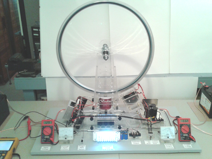
That is the picture on the cover of Bedini SG - The Complete Advanced Handbook. This was an A & P project to demonstrate a low drag generator since like Dave said, Peter mentioned that we're putting out the info but nobody seems to be building anything. That isn't entirely true but for the most part it is. I'm in touch with some people behind the scenes that wish to remain behind the scenes who have applied the information here are supplying a few hundred watts to power loads while the battery banks are staying fully charged.
The generator coil is immediately to the right of the main coil. 12 strands 100 feet long each all wired in series. The diode from the gen coil output is important. In any case, we can light that bank of LED's from the gen coil when the light bank switch is turned on. Quite often, the lights will come on and the RPM will drop 0 rpm. Sometimes it will drop a few. (I just looked in the Advanced SG book and the diagram Peter drew for it shows 10 windings and not 12 but it makes the same point).
The Watson Machine based on John's 1984 design has all the generator coils in series (not meaning each gen coil has parallel windings that are in series) - just that each generator coil in whole is in series with the next one around the periphery of the gen coil mounting plate. What you will also see that most people never noticed is that the magnets on the rotor are not over all the coils at the same time, they're staggered because there is a different number of magnets than coils like an odd number of magnets and even number of gen coils or visa versa. That eliminates the cogging from all magnet/coil combinations from happening at once. Is that optimum? You'll just have to do the tests and find out.
If the 1984 variation was running on the 3 battery system, it would have been way more amazing that it already was.
The Bedini SG as many people know is not a motor but an energizer. What most people don't realize even though it's right there in front of everyone, the SG actually does not have a prime mover - there is obviously no external motor to turn it as it is a self-rotating energizer - that does not mean it runs itself.
Muller lived a few hours from here in Penticton, BC from what I remember. I think there is a video with Peter Lindemann and someone else Aaron Kahn or Kan?? who gave some comments on Muller's setup after they visited him. If anyone has a copy of this, would be a good reference - I don't recall what their comments were because it has been so long. It may have just been a written report. That was probably 20 years ago. For core material, I think Muller liked black sand. Muller also may have been using a configuration of a different number of magnets than coils to stagger them like what is used on Watson's 1984 Bedini machine.Leave a comment:
-
This is very much on the same subject but a different apparatus altogether. On Muller's website which is unfortunately gone now...He described what he called Muller's special case. This is the same effect as the accelerating coils.
So the deal was you get a flat rectangular magnet, and 3 ball bearings of hard steel. You can put the bearing close to each other while going into the magnet field of the magnet until they stick but aren't pulled in yet. Then coax them towards the magnet until it pulls them in. The furthest ball will then shoot off with a pretty significant force. I never personally measured it appears to be greater then what would be expected from the kinetic energy developed from the collision. And most of the time it will not repeat itself on the same pole twice. You have to flip the magnet to get it to happen again.
Again I tell you this the same effect. It is a combination of impedance either electrical or magnetic coupled to the density of the core material or the maximum flux density (Bmax) of a material. Of course the Bmax is effected by frequency. Those frequencies will change the behavior of the coil. Some coils may accelerate at lower frequencies but most likely will not produce current but at the same time produce significant current at higher frequencies and not accelerate. Or vice versa.
What I know is there is no named force for this action. And I am not sure that the appearance of this action is always the same thing. As I believe is the case with the Kromrey.
MattLeave a comment:

Leave a comment: