Announcement

Collapse
No announcement yet.

3 Battery Generating System

Collapse
This topic is closed.
X
X
 
  • Filter
  • Time
  • Show
Clear All
new posts

  • posts moved

    All the off topic posts were moved here: http://www.energeticforum.com/free-e...d-dispute.html

    Chet, Carroll, etc. are welcome to comment there on those subjects.
    Sincerely,
    Aaron Murakami

    Books & Videos https://emediapress.com
    Conference http://energyscienceconference.com
    RPX & MWO http://vril.io

    Comment


    • Originally posted by Turion View Post
      There is a heck of a lot of research that
      needs to be done with a single coil

      And don’t even get me started on CORE material.

      Core material? Rods in iron dust would be easier to build so why
      didn't the electrical standard become that? That's and easy one
      so I'll answer my own question. Hmmmm....... Don't know but
      these microwave oven transformers sure do the job.

      A while back I spent some time on ferrite core mixtures Moly by
      golly and you name it, nickel, manganese, let me go back and think,
      where is that list? Anyway the percentages changed as various
      response curves were realized.

      One thing I am told is this discussion becomes all about getting so
      much flux from magnet into the core that it is saturated. Magnetic
      locking is not far away from maximum with nearing full saturation.

      I don't want that. I want to hit my cores like you would ring or ding
      a bell but saturation is like smashing my bell to be rung with a sludge
      hammer and then expect it to keep ringing, it just won't.

      I will give all of my next set of details coming up. We will get some
      idea where this is going as additional data are entered.

      A single coil may fool you into thinking that 2,3,4 to 12 coils all
      make for a better generator without a care in the world. No way.

      Cogging becomes the issue. Muller whipped that.

      All I am saying is that I did what I was led to do by Thane. He has
      never answered me on youtube, but he need not because all I did
      was thank him.

      Thane inspired me. First the bi-toroid and then I realized that the
      current delay could be produced on a scope with motor winding also.

      Thane is way out there with capturing the coil collapse for each and
      every pulse so I took the easy road and went with Matt's Mod Mtr
      so I could spend all my time on rotors.

      C cores are different from post cores, flux is transferred from the "N"
      to the "S" pole relieving the cogging, this is why Dave's first few rigs
      burned out motors. I am not kicking you Dave just gonna point out
      that you have never been an ultra mechanic from birth, never been a
      super hero engineer, no extra ordinary certifications pertaining to
      this type of work other than being highly perceptive. Genius.

      Starting for scratch Dave made it work good enough to keep the
      idea alive til he could make it twice as good. Things such as cogging
      like Muller taught is important as coils are added.

      Muller did that his way. "C" cores can reduce this, core area per sq
      inch of magnet area. No saturation plz. The last time I watched Thane
      he was getting his regenx coil (As he calls them, I call them Tesla Coils)
      to produce 50 percent of what the drive motor was using at 30 rpm's.

      You can't learn all of this in 5 minutes......................

      Comment


      • reduced drag generators

        Originally posted by Turion View Post
        Every coil you add to make the motor speed up under load also places a steel or iron core in the path of a rotating magnet, which SLOWS IT DOWN in the first place. The speed up under load ONLY happens when the rotor is ALREADY turning and you put a load on the coil. If you put a bunch of coils with iron cores around your rotor and try to start the motor, the attraction of the magnets to the iron is so great the motor CANT break it and start spinning, and the amp draw of the motor goes through the roof. Now, if your individual coils are introduced to a moving rotor, they will slow it down, but when you add a load they will speed it back up. There isn’t any GAIN. So when a rotor is ALREADY turning magnets past a bunch of coils with iron cores, the hard work is already DONE...getting the rotor to even turn. When you add a load the motor speeds up, but all you did was neutralize the “slow down”!the iron core of the coil was already responsible for. Or at least that is MY observation.
        I'm glad you posted this because this was the EXACT point I was going to make to BroMikey after asking a few more questions so that the point was going to be automatically apparent. Because if completely removing the gen rotor with magnets seriously unloads the prime mover, then that automatically tells the whole story but I'll elaborate anyway.

        @All, I posted that Thane Heins video - been years since I've seen that but keep in mind that virtually everything Thane says in that video is wrong. He is right about unloading the prime mover, but he doesn't know why. The polarity of the coil doesn't reverse only the voltage does, there IS current moving in the coils at high frequency that are wound bifilar pancake style, etc. I've explained things wrong in the past even though I can make things work so obviously the explanation being wrong doesn't invalidate the actual results.

        Years ago Rick F. had the bicycle wheel with the generator coil that kept itself charged up - at least until the batteries started failing. An important distinction is that just because the batteries did fail (he didn't want to admit it but they did), that in itself does not mean it wasn't overunity. If the total work done was more than what the battery is rated for, then it is overunity automatically. The magnets on the rotor were N S alternating so the generator coil had a decent sine wave. There were a lot of windings to my recollection and it put out something like 1000 volts or something - it was pretty high. Bedini did discuss that the coil was also acting as a capacitor - similar to what Thane believes but it still acts a coils, still generates a magnetic field, etc.

        In all of these situations, the prime mover is already pre-loaded. This is the case with Rick's setup, it is the case with Thane's setups, it is the case with the Kromrey and it is the case with the generator concept here of unloading the prime mover. This is also the same as the 1984 or "Watson" machine setup.

        If I decouple the Kromrey generator from the DC motor turning it and the coils are open circuited with no load, that motor input will run for next to nothing. Why? Because all the "unloaded" claims are actually false.

        The only unloaded condition is when the generator coils and generator magnets on the rotor are not influencing each other. Dave's explanation above in my opinion is more than just his observation, it's an easily provable fact.

        Open circuit the generator coils with the generator rotor and magnets and see what the prime mover draws and then leave the gen coils open circuit and completely remove the generator rotor with magnets. The prime mover input goes way down because the magnets are no longer attracted to the cores in the gen coils whether there is a load or not. That means the "unloaded" generator section is actually always under a load.

        So we're not going to get away from the fact that if there are magnets on a generator rotor moving past generator coils loaded or not, the prime mover is always loaded.

        What we can do is simply reduce that magnetic drag. Using ideas like a different number of gen magnets than coils so all the cogging doesn't happen at once, etc. John was always pointing that out. So there are multiple ideas that can be used at the same time to take the results through the roof.

        Thane claims his system has no back emf, etc. and this contributes to "accelerating" his prime mover but what he is actually doing during those times is just reducing the pre-loaded condition giving the appearance that it causes the prime mover to accelerate. Not only is there back emf in play in his generator coils despite the claims, it is BECAUSE OF the back emf that the magnetic cogging is reduced. It amazes me that all the "experts" in the correspondence letters from Thane never got this because they're basic magneto principles.

        When gen coils are open circuit, the magnets on the gen rotor are attracted to the magnets at a certain strength. Let's say that permanent magnetic strength is 10 and the core's attraction ability is 10.

        If you short circuit the coils, the gen coils will develop back emf causing a like magnetic field that reduce the core's attraction strength to the magnets from 10 down to 5 for example. The magnet strength is still 10, but it's ability to be attracted to the core is not not as strong since there is a like field. Just because a magnetic field is there at the gen coil core does not mean it is automatically not attracted by the magnet because it happens at different strengths.

        Because the attraction to the core in this example is reduced from the magnetic field, which will not be that strong, the magnet on the gen rotor can glide by easier so the prime mover's draw will be reduced. The shorted coils did not accelerate the prime mover, it just reduced the cogging so the prime mover can speed up since it doesn't work as hard. Loading the coils does the same thing to different degrees. Even if the back emf is so small that it generates a like field that is ultra weak like 1 (10 being strongest), that is enough to neutralize the attraction of the magnets to the core a bit, a like field of 5 will do even more and 10 strength magnetic field on that gen coil might be way too much so it is all a balancing act of what you are after.

        So in the end, Thane's gen coil method works and it is because of back emf and not the lack of. Kromrey used the same methods back in the 60's and I'm sure others have done the same way before that. These effects were known very well by those who worked with magnetos in the early 1900s and Bedini turned me on to looking in that direction years ago.

        This came out years ago:

        [VIDEO]https://www.youtube.com/watch?v=LQE6NDukErg[/VIDEO]

        Mervace I believe was his name or nickname - John Bedini looked at the twisted wires going up in the air and told me it was eye candy for the ignorant - his exact words. Later on Mervace said it was all a hoax and that it was actually powered remotely by a CB radio. That may or may not be true, we'll never know.

        However, one of John's friends actually got it to work and had it running on its own with these magneto principles. The magnet had a free attraction towards the core, induced some current into the coil with a cap in parallel, right when the magnet got to the half way, there was a small glass reed switch that shorted the coil, the small back emf developed created an weak opposing magnetic field that let the magnet pull away with virtually no drag. The free attraction of the magnet to core of the coil when the magnet was approaching was stronger than the magnets attraction to the core of the coil when it was leaving. So the forces involved were a net positive force in one direction that allowed the "rotor" to continue to turn over and over. At least, that is my basic understanding of how it worked and it was definitely not powered by a CB. I believe it was real and so did John. This was around 2001 when I worked a few buildings down from John and Brett N. was working with him at that time.

        John encouraged me to build it and I tried but did not succeed - my build was very crude, but I believe the possibility is definitely there with these generator concepts to not just have a reduced drag effect as described above, but a completely drag free generator but it requires careful timing of applying the gen output to a load. You could then get all the benefits of the free attraction of the gen magnet to coil core, but none of the drag when the magnet is leaving the core.
        Sincerely,
        Aaron Murakami

        Books & Videos https://emediapress.com
        Conference http://energyscienceconference.com
        RPX & MWO http://vril.io

        Comment


        • Thoughts

          I have a whole bunch of U shaped cores I have been meaning to do some experiments with, but they are laminated cores. I will get to it some day. I have looked at the generating production of solid U shaped cores vs straight cores. I know which cores I like bested for what reason.

          If you have iron cores, U shaped straight cores, or X, Y or Z shaped and you plan to run the generator for hours on end, you better have a fire extinguisher handy. Those cores are going to heat up from the constant changing of the the flux in the core and then the coating on the wire is going to melt and then they are going to short out. And then Houston, we have a problem. I had plastic spacers on both sides of my rotors that are 4 inches thick, and on the outside of them are washers with retaining nuts. Those washers melted right into the plastic spacers.

          I have straight cores on all 12 of my coils, and I found a way to eliminate the magnetic cogging. My rotors, even with large 2" neo magnets and iron cores in all the coils, would still rotate by hand.

          You have to look at the OUTPUT of your coil and decide what you want to use and then figure out a way to make that work for you.
          “Advances are made by answering questions. Discoveries are made by questioning answers.”
          —Bernhard Haisch, Astrophysicist

          Comment


          • Originally posted by Aaron View Post
            I'm glad you posted this because this was the EXACT point I was going to make to BroMikey .........


            Because the attraction to the core in this example is reduced from
            the magnetic field, which will not be that strong, the magnet on the
            gen rotor can glide by easier so the prime mover's draw will be
            \reduced. The shorted coils did not accelerate the prime mover,
            it just reduced the cogging so the prime mover can speed up since
            it doesn't work as hard. Loading the coils does the same thing to
            different degrees. Even if the back emf is so small that it generates
            a like field that is ultra weak like 1 (10 being strongest), that is
            enough to neutralize the attraction of the magnets to the core a
            bit, a like field of 5 will do even more and 10 strength magnetic field
            on that gen coil might be way too much so it is all a balancing act
            of what you are after.

            See, I knew there had to be someone better than me to explain
            some of this. The greater number of parallel wound series connected
            coils give you "more options" to quote Dave. So as I began this
            exploration i was directed to use 24 stranded coils. The first coil would
            drag down the rotor so I went to the second and so on til something
            happened. Along about the 6th, 7th and 8th strand I was noticing
            that I could get power out of my coil but the rotor action was unaffected.

            In other words the rotor speed never changed which signifies that the
            prime mover or drive motor current was no longer climbing up when
            loading down the generator coil. Now I have the length, each strand is
            175 feet and I had 6 or 8 of them rewired up in series to form a coil
            that is 175 X 8 we will say this = 1400 feet.

            So now I can go wind coils 1400 feet and they will always do the same
            thing right? Wrong because without the parallel wound series connected
            pattern I lost my small amount of capacitance which changes everything.

            Now I know guys like Thane never divulge coil details so we will never
            know how his are laid out, but from his patents it must be close.

            This is all based on Telsa coils as shown to us by Dave.

            After that I continued on to each successive strand which added
            energy to the rotor action and less to the output of the coil. So as
            I went higher with the number of strands I found I could lower the RPM's
            and still get assisted rotor action. 15, 16, 17, 18 faster and faster.

            That means with enough "Options" (strands) I can do some switching
            for start up to keep my drive motor from burning up. So much to
            consider. Hope everyone has some extra time.

            Comment


            • Clarification

              If you run generator coils with iron cores for too long you will melt the insulation off your wires and away goes the capacitance of wires in parallel and your output is screwed up and your amp draw goes up on the motor. Iron cores HEAT UP.

              “Options” is why I recommended 24 strands of #23 on that particular coil bobbin. You keep putting strands in series until it speeds up under load with the number of magnets YOU are using at the rpm YOU are running at with the core mass YOU have in YOUR coils. You don’t have to exactly replicate MY coil. You build the coil to work on YOUR machine not mine. Hopefully it will be 6,8 or 12 strands in series. 12 will work on any REAL machine, and the better your machine the fewer strands you will need in series. If it needs more than 12, you need more magnets on your Totoro you need to run th motor faster.
              “Advances are made by answering questions. Discoveries are made by questioning answers.”
              —Bernhard Haisch, Astrophysicist

              Comment


              • parallel series coils

                Originally posted by BroMikey View Post
                The greater number of parallel wound series connected coils give you "more options" to quote Dave.

                That means with enough "Options" (strands) I can do some switching
                for start up to keep my drive motor from burning up. So much to
                consider. Hope everyone has some extra time.
                When Peter and I wound the generator coil on the bicycle wheel SG where it lit a bank of LED's but didn't change the rpm of the wheel, I think we used 12 wires - each 100 ft long all wound together together then we series them. I'm not saying that is the optimum setup - just what we used but yes, that is the idea. A different number may have worked better but we just needed something to prove the point for Peter's presentation on that machine. Many of those low drag concepts are in the Advanced SG book from the trilogy.

                The only way to know what works best for your setup is that you have to determine it experimentally.
                Sincerely,
                Aaron Murakami

                Books & Videos https://emediapress.com
                Conference http://energyscienceconference.com
                RPX & MWO http://vril.io

                Comment


                • Originally posted by Aaron View Post
                  When Peter and I wound the generator coil on the bicycle wheel SG where it lit a bank of LED's but didn't change the rpm of the wheel, I think we used 12 wires - each 100 ft long all wound together together then we series them.
                  I KNEW IT, I KNEW you guys did this years ago but most times stuff
                  get over looks for years cause we got to work for a living also.

                  I remember all those huge generator coils, come on people think back,
                  this the way i talk to myself too. Does anyone remember those giant
                  generator coils with a single strand a million miles long? Back in the day? John would hook 5 coils all around his SG's in series.

                  John hooked them all up in series. Anybody? Humm...........
                  Last edited by BroMikey; 03-26-2018, 09:32 AM.

                  Comment


                  • Flux in the core

                    when you align the electrons in steel with a passing magnet and then allow them to return to normal, you are going to get heat. The more you do it the more heat you get. Yes, larger magnets cause it to happen SOONER. So does running a rotor at a higher speed than you NEED to. So does having more magnets on the rotor.

                    In every build there are things you must balance. What is the PURPOSE of your generator? Is it to run a big load? Is it to run your house? Is it to run a small load? Is it to replace your solar panels and keep your battery bank charged? You want to build the generator that will MEET your need and run as long as you need it to run without overheating. Your goal is not to build the biggest baddest generator that ever rotated.

                    If you have read Muller’s Work you know he did NOT use an external motor. His motor and generator were ONE. WE DID use an external motor, but ONLY because we wanted to put out something SIMPLE with the modified MATT motor that could be built by ANYONE without ANY understanding of electronic circuits, transistors, potentiometers, relays or anything else. Something ANYBODY could build for a few bucks that would PROVE the 3 Battery System works. “Come on in, the water’s fine!” It was very interesting to me that in the Beyond the Advanced SG, Peter says he built that machine for the conference because “Nobody is building this stuff.” He was right. Look how long Matt and I had been discussing the 3 Battery stuff on the thread at that point (like 8 years) and because we REFUSED to show demonstrations of working systems running our house, NOBODY was replicating. They still aren’t, and it is their loss. John B never showed running the SG on a 3 Battery setup. Nowhere can I find where he talked about the advantages of using that system. Obviously he KNEW about running between the positives because that is the basis for the Tesla Switch, but how deep did he go? Matt has built working Tesla Switch systems, and I can tell you what his advise would be about running your house on a Tesla Switch System. Solar is CHEAPER per kilowatt hour of energy and Tesla Switches run on such a thin margin of success that if the temperature of your batteries drop because it turns cold outside, it all goes downhill fast.

                    So three batteries and a motor. Simple. Get your feet wet. Add a $3.00 off the shelf boost module if you are a little more adventurous and now you REALLY have something and you are only up to your ankles. Just run it and look at the data. Build a generator if you really want to get output and now you are up to your knees.

                    Can this be taken further? Absolutely! Get rid of the external motor and you are up to your neck. Run it exactly the way Muller did as both a motor AND a generator with an advantage HE NEVER HAD. YOU can run it on a 3 Battery System. Deeper than that? We think so. Electrical systems that move energy from one potential to another potential doing work on the way with no moving parts, HOPEFULLY, without all the batteries required by the Tesla Switch. Now you’re probably in over your head, but you aren’t forced to swim until the water gets deep enough that you can’t touch the bottom. If this work is ever going to go foreword we need a whole lot of people splashing about in the deep end, not sitting on the bank afraid to stick their toe in the water. People who can’t swim in the deep end of the pool certainly have no business out in the ocean, so there’s no use even talking to them about what could be out there.
                    Last edited by Turion; 03-26-2018, 11:38 AM.
                    “Advances are made by answering questions. Discoveries are made by questioning answers.”
                    —Bernhard Haisch, Astrophysicist

                    Comment


                    • Talk about on subject !!!!

                      Totoro? Miyazaki's animated character in our favorite Japanese carton. So a fat coil?

                      I'm ready to tread water. #1. I know the core material is very important to prevent heating. That must be overcame. #2. Prime mover done away with and build a motor/generator. I've tried to build a "Lockridge" device for years now. Got all the old generators laying around collecting dust. #3. System powered by 3BGS as I learned from my last build.

                      I'm not Michael Phelps but I will try to keep up.

                      wantomake

                      Comment


                      • Generator

                        Here is everything I am willing to share about my generator at this time. This is probably the 6th version I built. The 7th had a thicker piece of plastic to keep the coils away from the rotor. The 8th had only 5 sets of coils so an even number of magnets and an odd number of coils. The 9th had no magnetic lock. Hope this helps.

                        Generator Review - YouTube
                        “Advances are made by answering questions. Discoveries are made by questioning answers.”
                        —Bernhard Haisch, Astrophysicist

                        Comment


                        • Hi Dave,

                          thanks for all the good advice. After a few months break I've started playing with my setup again.
                          Like you said, when you introduce the coil with iron core to the spinning rotor, the rotor slows down. When you add the load it speeds up again. Question: have you ever been able to make it speed up (with load or shorting the output) to the exact same rpm you had without the coil/core in front of the rotor?

                          cheers,
                          Mario

                          Comment


                          • This is very much on the same subject but a different apparatus altogether. On Muller's website which is unfortunately gone now...He described what he called Muller's special case. This is the same effect as the accelerating coils.
                            So the deal was you get a flat rectangular magnet, and 3 ball bearings of hard steel. You can put the bearing close to each other while going into the magnet field of the magnet until they stick but aren't pulled in yet. Then coax them towards the magnet until it pulls them in. The furthest ball will then shoot off with a pretty significant force. I never personally measured it appears to be greater then what would be expected from the kinetic energy developed from the collision. And most of the time it will not repeat itself on the same pole twice. You have to flip the magnet to get it to happen again.

                            Again I tell you this the same effect. It is a combination of impedance either electrical or magnetic coupled to the density of the core material or the maximum flux density (Bmax) of a material. Of course the Bmax is effected by frequency. Those frequencies will change the behavior of the coil. Some coils may accelerate at lower frequencies but most likely will not produce current but at the same time produce significant current at higher frequencies and not accelerate. Or vice versa.

                            What I know is there is no named force for this action. And I am not sure that the appearance of this action is always the same thing. As I believe is the case with the Kromrey.

                            Matt

                            Comment


                            • generator coils

                              Originally posted by BroMikey View Post
                              I KNEW IT, I KNEW you guys did this years ago but most times stuff
                              get over looks for years cause we got to work for a living also.

                              I remember all those huge generator coils, come on people think back,
                              this the way i talk to myself too. Does anyone remember those giant
                              generator coils with a single strand a million miles long? Back in the day? John would hook 5 coils all around his SG's in series.

                              John hooked them all up in series. Anybody? Humm...........
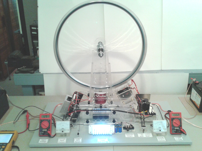
                              The exact SG that this 12 strand generator coil was is in this picture:


                              That is the picture on the cover of Bedini SG - The Complete Advanced Handbook. This was an A & P project to demonstrate a low drag generator since like Dave said, Peter mentioned that we're putting out the info but nobody seems to be building anything. That isn't entirely true but for the most part it is. I'm in touch with some people behind the scenes that wish to remain behind the scenes who have applied the information here are supplying a few hundred watts to power loads while the battery banks are staying fully charged.

                              The generator coil is immediately to the right of the main coil. 12 strands 100 feet long each all wired in series. The diode from the gen coil output is important. In any case, we can light that bank of LED's from the gen coil when the light bank switch is turned on. Quite often, the lights will come on and the RPM will drop 0 rpm. Sometimes it will drop a few. (I just looked in the Advanced SG book and the diagram Peter drew for it shows 10 windings and not 12 but it makes the same point).


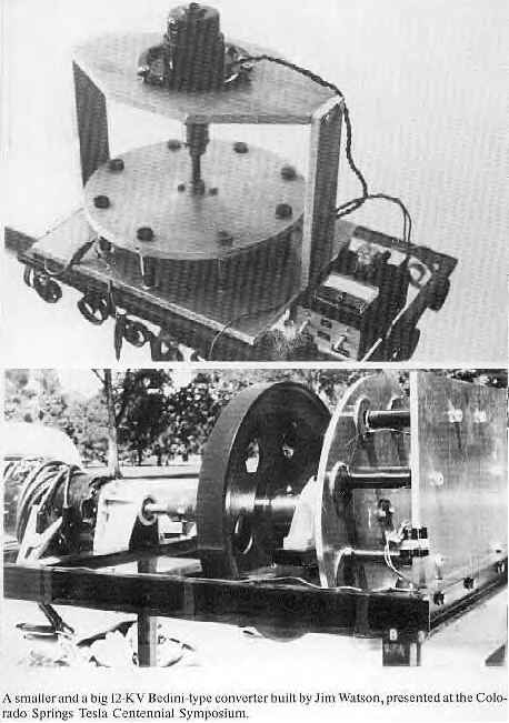
                              The Watson Machine based on John's 1984 design has all the generator coils in series (not meaning each gen coil has parallel windings that are in series) - just that each generator coil in whole is in series with the next one around the periphery of the gen coil mounting plate. What you will also see that most people never noticed is that the magnets on the rotor are not over all the coils at the same time, they're staggered because there is a different number of magnets than coils like an odd number of magnets and even number of gen coils or visa versa. That eliminates the cogging from all magnet/coil combinations from happening at once. Is that optimum? You'll just have to do the tests and find out.

                              If the 1984 variation was running on the 3 battery system, it would have been way more amazing that it already was.

                              The Bedini SG as many people know is not a motor but an energizer. What most people don't realize even though it's right there in front of everyone, the SG actually does not have a prime mover - there is obviously no external motor to turn it as it is a self-rotating energizer - that does not mean it runs itself.

                              Muller lived a few hours from here in Penticton, BC from what I remember. I think there is a video with Peter Lindemann and someone else Aaron Kahn or Kan?? who gave some comments on Muller's setup after they visited him. If anyone has a copy of this, would be a good reference - I don't recall what their comments were because it has been so long. It may have just been a written report. That was probably 20 years ago. For core material, I think Muller liked black sand. Muller also may have been using a configuration of a different number of magnets than coils to stagger them like what is used on Watson's 1984 Bedini machine.
                              Sincerely,
                              Aaron Murakami

                              Books & Videos https://emediapress.com
                              Conference http://energyscienceconference.com
                              RPX & MWO http://vril.io

                              Comment


                              • self-rotating energizer

                                Originally posted by Turion View Post
                                Here is everything I am willing to share about my generator at this time. This is probably the 6th version I built. The 7th had a thicker piece of plastic to keep the coils away from the rotor. The 8th had only 5 sets of coils so an even number of magnets and an odd number of coils. The 9th had no magnetic lock. Hope this helps.

                                Generator Review - YouTube
                                Nice test setup!

                                I can tell you also as a matter of fact that the Kromrey's prime mover is also unnecessary. I think it is a bit of common sense but I do the experiments anyway. The simple SG topology itself should be all that is necessary for anyone to derive this understanding of how to turn any generator coil into a self-rotating energizer. At least one variation. And it depends on what output of the gen coils anyone wants - the spike, sine wave, galloping dc by rectifying the ac, etc. or a combination of those outputs depending on the delay of the on power for a certain % of the rotation and/or if you multiple stacks of gen coils separate from the rotating energizer section.

                                If any of you switch power to the gen coils from a battery, it will obviously push or pull a magnet on a rotor and will let you get rid of the prime mover.

                                Another consideration is that depending on the frequency, it is important to make sure that the coil is fully discharged before applying power to it again or you will buck against the collapse and that just creates a lot of waste/heat - that is if you want to run the gen coils as a self-rotating energizer.

                                When Paul Babcock says "zero-stating the inductors", that is what it means and is why he has the "reduced impedance effect." He can run his coils at high frequencies and the coils stay close to room temperature. Many people think that coils discharge so fast that it will always be fully discharged when the next on power cycle happens, but that isn't true. Without the way Paul does it, most people will not be able to run the coils at the same frequencies with the same power without creating a heater.
                                Last edited by Aaron; 04-13-2018, 12:38 AM.
                                Sincerely,
                                Aaron Murakami

                                Books & Videos https://emediapress.com
                                Conference http://energyscienceconference.com
                                RPX & MWO http://vril.io

                                Comment

                                Working...
                                X