Announcement

Collapse
No announcement yet.

Parameter Variation Machines With focus on EPD FQToEW, JF Murray, Manelstam & Papalex

Collapse
X
 
  • Filter
  • Time
  • Show
Clear All
new posts

  • #31
    Originally posted by garrettm4 View Post
    In the meanwhile, here's the first two pages of a book I have been reading regarding this general topic. While its oriented towards radio/microwave circuits, it is still definitely worth taking a look at.

    Semiconductor-Diode Parametric Amplifiers 1961 by Lawrence A. Blackwell and Kenneth L. Kotzebue (compliments of HathiTrust)


    For some more fun reads on the subject (via HathiTrust) check out:

    Self-Saturating Magnetic Amplifiers 1960 by Gordon E. Lynn

    Magnetic Amplifiers, Theory and Application 1958 by Sidney Platt
    I found a way to download these books from HathiTrust. It takes a while for my computer to download all the individual images and make a pdf from it, but it works.

    Already finished the Blackwell book, which I uploaded together with some other info I could find to my server:

    Directory contents of /pdf/Reference_Material/Parametric_Excitation/

    Will upload the other two books in the coming days to the "Magnetic Amplifiers" section:

    Directory contents of /pdf/Reference_Material/Magnetic_Amplifiers/

    Also renamed the "report" file I had on Mandelstam and Papalexi. This is a 60 page NASA translation of a 1935 article in Russian:
    http://www.tuks.nl/pdf/Reference_Mat...ion%201969.pdf

    This appears to be the paper referred to by Janssen in his "Investigations of Parametric Excitation in Physical Systems" (2005):

    http://www.tuks.nl/pdf/Reference_Mat...20-%202005.pdf

    In 1935 a Russian paper was published by L. Mandelstam, N. Papalexi, A. Andronov, S. Chaikin and A. Witt. The title of the paper was “Report on Recent Research on Nonlinear Oscillations”. In this paper, the authors discuss many types of nonlinear oscillations. One chapter is dedicated to parametric excitation of nonlinear circuits. I came across references to this paper two different times. Once was when professor Denardo mentioned that one of his books referenced it. The other time was when I was doing a Google search for parametric excitation. The website, The Tom Bearden Website (29 APR 05) seemed unreliable due to its content, which mostly consisted of claims for free energy without proof. I nevertheless decided to investigate the reference. I found a few more references to the paper on-line but no directions where to find it. After consulting with NPS librarian Michaele Huygen and searching many online resources of the library, I found a copy of the paper in English. The paper had been translated from Russian to French to English. The copy that I had found was produced by NASA Technical Translation.

    Janssen also discusses the Rotary Electrostatic Converter, which has actually been built in practive by Chris Carson based on Eric's theory:

    B. THEORY OF A CAPACITANCE-MODULATED CIRCUIT

    To modulate the capacitance of an LC circuit, we consider a bank of n parallel sectored plates, where every other plate is electrically connected, and where one set of plates is rotated (Fig. 10). This configuration amounts to n – 1 identical variable capacitors in parallel (n = 10 in Fig. 10).

    Tuks Unsorted KieknWatTWordt Stuff : Energetic Form Posts

    Comment


    • #32
      Hi Andrew,

      I found a reference to elnamagnetics where there may be a chance to get metglas cores or you can inquire for specific types:

      Elna Magnetics | Search Results

      Sorry if you have been aware of this already. I do not know them, have never ordered any from them.

      Gyula
      Hello again!
      I contacted those guys first as they are a distributor for Hitatchi, but they referred me back to the parent company because all they had were very very small ones, for the larger ones I needed to go to the big guys, I got the run around for a very long time even though promising a possible purchase of over 10,000 which any salesman would jump on and send samples out for, even if I have to pay for the samples I would have done so.

      P.S. Raui....

      Regular MetGlass cores are not what we want. I have several of those which are very nice indeed, (over 200$ a core) but the deal is that they do not have the square B-H loop we are looking for. We want a very small input to wildly change the inductance of the core, these are almost like the mosfets of magnetism.

      Comment


      • #33
        Found a great resource on Mandelstam, Papalexi, etc.

        This site has quite a lot of translations of the Mandelstam and Papalexi articles:

        National ElectroDynamics, LLC : Translation Publications

        Currently uploading them to my archive:

        Directory contents of /pdf/Reference_Material/Parametric_Excitation/

        Comment


        • #34
          Originally posted by Armagdn03 View Post
          Hello again!
          I contacted those guys first as they are a distributor for Hitatchi, but they referred me back to the parent company because all they had were very very small ones, for the larger ones I needed to go to the big guys, I got the run around for a very long time even though promising a possible purchase of over 10,000 which any salesman would jump on and send samples out for, even if I have to pay for the samples I would have done so.

          P.S. Raui....

          Regular MetGlass cores are not what we want. I have several of those which are very nice indeed, (over 200$ a core) but the deal is that they do not have the square B-H loop we are looking for. We want a very small input to wildly change the inductance of the core, these are almost like the mosfets of magnetism.
          Hi Andrew,

          Maybe for just as a 'remote substitute' you could consider testing toroidal ferrite cores manufactured with square loop B/H curve. Ferroxcube has such and designates them as 3R1 material. Data sheet:
          http://www.ferroxcube.com/prod/assets/3r1.pdf

          Ordering is from Newark or Farnell
          TN36/23/15-3R1 - FERROXCUBE - TOROID | Newark

          This OD=36mm seems to be highest diameter, and there are smaller ones.

          rgds, Gyula

          Comment


          • #35
            Originally posted by Armagdn03 View Post
            Hello again!
            I contacted those guys first as they are a distributor for Hitatchi, but they referred me back to the parent company because all they had were very very small ones, for the larger ones I needed to go to the big guys, I got the run around for a very long time even though promising a possible purchase of over 10,000 which any salesman would jump on and send samples out for, even if I have to pay for the samples I would have done so.

            P.S. Raui....

            Regular MetGlass cores are not what we want. I have several of those which are very nice indeed, (over 200$ a core) but the deal is that they do not have the square B-H loop we are looking for. We want a very small input to wildly change the inductance of the core, these are almost like the mosfets of magnetism.
            I remember reading on their site that they had cores for magamps, are these not suitable? I just did another quick search and found that I was directed to hitachi about these "square loop" metglas cores although last time I could view the information directly from the methods site. Are these the same cores you were looking to buy from hitachi: MAGAMP Square Loop Cores : Amorophous Products : Hitachi Metals America
            http://www.hitachimetals.com/product...magamp_opt.pdf

            From the data sheet they seem to have a decent b/h loop. I know that any old core will not do but I thought these cores would be suitable?

            Raui
            Scribd account; http://www.scribd.com/raui

            Comment


            • #36
              MagAmp Cores

              I was able to sample a core from MetGlas, this was before Hitachi took them over, and ironically the amorphous metal team were originally a division of Honeywell. I happen to know a guy who knows the guy who was over that division of Honeywell.

              Strangely, the only saturable reactor sample, of which they were willing to send my way (paid sample or not), was a tiny little toroid; OD 33.865mm, ID 21.687mm, Ht 11.049mm. Which was of the amorphous alloy type 2714A, of which you can buy by the tape reel rather than the pre-wound toroids. (If I were to contact them again I would now ask for the tape reels as opposed to pre-wound cores. Thanes B Heinz seems to use the metal tape from these guys as well.)

              The MP3210M4AS type 2714A alloy tape wound toroid, once received, was tested by myself to be fairly square and saturate quite easily. Cobalt based alloys seem to be superior to the nickle based alloys from what I have seen, low hysteresis losses and good squareness ratios.

              Due to the small core I received, and the alloy used, it literally took milli-amps to effectively saturate the core, with the proper turn count or ampere-turn product. Important, you don't want the power winding to saturate the core for you! So for those who are going down this route (of using pre-made toroids), use the minimal ampere-turns tolerable for the power winding and as many cores as tolerable, connected in series or parallel. I have seen people stack multiple cores together as a single unit, which is another way to better utilize them. You want to run the reactor cores at about 70% or less of their saturation points on the power side and 100% on the control winding when its energized, this way the core actually looks like a stable inductance to the ac source when you aren't driving it.

              Also, you may or may not need a non-saturable reactor in front of your saturable reactor, this is to limit the current in-rush from the end of the zero-crossing, when the core is saturated by the control winding, to the peak of the current node. The current magnitude allowed to flow through, when the reactor is saturated, is VERY important! This value needs to be LOWER than the saturating ampere-turn product or saturating current sheet value. As Dave has seen in his work, there is a sweet spot in setting the MAX current flow through the saturable reactor for excess energy return.

              However there is no magic here, if the core remains saturated when the control winding is off (due to over current in the power winding), you obviously will get less than maximum energy back because there wasn't enough room to store the energy present let alone the energy the ferromagnetic material would have been able to impart from the artificial saturation by the control winding. So when designing a setup make ample room for the flux density of the power winding. This was something I found out the hard way, through much trial and error. So I hope this brief discussion helps someone achieve faster results and better success than what I was able to do.

              I want to note, that with a mechanical parameter variation machine, built using standard grain oriented silicon steel, the operational characteristics are vastly different from a static satureable reactor using a cobalt or nickle alloy, don't confuse the two as to how they operate. Mr. Dollard has given a tour de force series of recent transmissions, "Law of Electro-Magnetic Induction", which in the latter parts describes the operational differences between the two distinct modes. Also, when employing higher flux densities, a mechanical unit might be more desirable than the static saturable reactor design, this from what I have seen on the bench. However, when operating at higher frequencies, the static saturable reactors are the better design. Each have their respective merits, so don't get hung up on one over the other.

              One more thing, the Gorden E Lynn and Sydney Platt book references I gave, in a prior post, cover the static saturable reactor subject intimately. I highly suggest reading both of them before building a unit.

              *On a side note, "ferro-electric capacitors" with a highly square hysteresis loop are the equivalent of a "dielectric magamp". The company that sold these parts in the USA signed an agreement with the USN (navy) that prevented them to sell any of their square loop ferro-electric capacitors to anyone but the USN. I don't want to say this is a conspiracy in the sense that people are being silenced, but realistically, AVAILABILITY is what's being regulated here. The same thing is seen with saturable reactors, the availability to customers is very limited and may most likely be under observation. Whereby the quantity sold and samples given by each company may have to be reported to some sort of "agency", what that hypothetical agency does with this information is beyond me. While I'm not in to conspiracies, it is interesting however, to see the correlations on the poor availability and also the possibilities these materials posses when used in an unorthodox manner, i.e. over-unity electrical systems.

              Good Luck,
              Garrett M
              Last edited by garrettm4; 07-30-2012, 12:16 AM.

              Comment


              • #37
                Originally posted by Raui View Post
                I tried getting some custom metglas cores back at the start of the year when I had a bit of money to throw around and I never heard back so that makes 3 of us..dare call it conspiracy?
                Make that 4. I have contacted several dozen companies trying to get high permeability core material, and it's very difficult to get a response. One of these days I'll fly over to India (where the Metglas plant is) and go to the factory direct....
                A collection of Eric Dollards latest posts and writings on my website: Gestalt Reality - Eric Dollard

                Comment


                • #38
                  Originally posted by Raui View Post
                  I remember reading on their site that they had cores for magamps, are these not suitable? I just did another quick search and found that I was directed to hitachi about these "square loop" metglas cores although last time I could view the information directly from the methods site. Are these the same cores you were looking to buy from hitachi: MAGAMP Square Loop Cores : Amorophous Products : Hitachi Metals America
                  http://www.hitachimetals.com/product...magamp_opt.pdf

                  From the data sheet they seem to have a decent b/h loop. I know that any old core will not do but I thought these cores would be suitable?

                  Raui
                  OH gotcha, yes they do have square loop cores, I thought you were referring to their normal amorphous ones which do not behave this way, sorry for misunderstanding.

                  Comment


                  • #39
                    Originally posted by garrettm4 View Post
                    I was able to sample a core from MetGlas, this was before Hitachi took them over, and ironically the amorphous metal team were originally a division of Honeywell. I happen to know a guy who knows the guy who was over that division of Honeywell.

                    Strangely, the only saturable reactor sample, of which they were willing to send my way (paid sample or not), was a tiny little toroid; OD 25.658mm, ID 18.512mm, Ht 11.049mm. Which was of the amorphous alloy type 2714A, of which you can buy by the tape reel rather than the pre-wound toroids. (If I were to contact them again I would now ask for the tape reels as opposed to pre-wound cores. Thanes B Heinz seems to use the metal tape from these guys as well.)

                    The MP2410M4AS type 2714A alloy tape wound toroid, once received, was tested by myself to be fairly square and saturate quite easily. Cobalt based alloys seem to be superior to the nickle based alloys from what I have seen, low hysteresis losses and good squareness ratios.

                    Due to the small core I received, and the alloy used, it literally took milli-amps to effectively saturate the core, with the proper turn count or ampere-turn product. Important, you don't want the power winding to saturate the core for you! So for those who are going down this route (of using pre-made toroids), use the minimal ampere-turns tolerable for the power winding and as many cores as tolerable, connected in series or parallel. I have seen people stack multiple cores together as a single unit, which is another way to better utilize them. You want to run the reactor cores at about 70% or less of their saturation points on the power side and 100% on the control winding when its energized, this way the core actually looks like a stable inductance to the ac source when you aren't driving it.

                    Also, you may or may not need a non-saturable reactor in front of your saturable reactor, this is to limit the current in-rush from the end of the zero-crossing when the core is saturated, to the peak of the current node. The current magnitude allowed to flow through, when the reactor is saturated, is VERY important! This value needs to be LOWER than the saturating ampere-turn product or saturating current sheet value. As Dave has seen in his work, there is a sweet spot in setting the MAX current flow through the saturable reactor for excess energy return.

                    However there is no magic here, if the core remains saturated when the control winding is off (due to over current in the power winding), you obviously will get less than maximum energy back because there wasn't enough room to store the energy present let alone the energy the ferromagnetic material would have been able to impart from the artificial saturation by the control winding. So when designing a setup make ample room for the flux density of the power winding. This was something I found out the hard way, through much trial and error. So I hope this brief discussion helps someone achieve faster results and better success than what I was able to do.

                    I want to note, that with a mechanical parameter variation machine, built using standard grain oriented silicon steel, the operational characteristics are vastly different from a static satureable reactor using a cobalt or nickle alloy, don't confuse the two as to how they operate. Mr. Dollard has given a tour de force series of recent transmissions, "Law of Electro-Magnetic Induction", which in the latter parts describes the operational differences between the two distinct modes. Also, when employing higher flux densities, a mechanical unit might be more desirable than the static saturable reactor design, this from what I have seen on the bench. However, when operating at higher frequencies, the static saturable reactors are the better design. Each have their respective merits, so don't get hung up on one over the other.

                    One more thing, the Gorden E Lynn and Sydney Platt book references I gave, in a prior post, cover the static saturable reactor subject intimately. I highly suggest reading both of them before building a unit.

                    *On a side note, "ferro-electric capacitors" with a highly square hysteresis loop are the equivalent of a "dielectric magamp". The company that sold these parts in the USA signed an agreement with the USN (navy) that prevented them to sell any of their square loop ferro-electric capacitors to anyone but the USN. I don't want to say this is a conspiracy in the sense that people are being silenced, but realistically, AVAILABILITY is what's being regulated here. The same thing is seen with saturable reactors, the availability to customers is very limited and may most likely be under observation. Whereby the quantity sold and samples given by each company may have to be reported to some sort of "agency", what that hypothetical agency does with this information is beyond me. While I'm not in to conspiracies, it is interesting however, to see the correlations on the poor availability and also the possibilities these materials posses when used in an unorthodox manner, i.e. over-unity electrical systems.

                    Good Luck,
                    Garrett M

                    There is a very interesting experiment I tried recently using a few cores I had laying around. which may solve the problem you are describing, and give some direction on how to use saturable reactor cores.


                    This was basically the setup. However in one iteration I used a toroidal core which was split into two C sections with with a paper in-between to create a small gap.

                    This setup is very similar to the Alexanderson setup, in that the two windings are not inductively coupled in the traditional sense. A change in B field with respect to time in one does not create an EMF in the other.

                    Placing an alternating current through the black winding does not affect the red winding, until there is an external magnetic field applied. When the external field is applied it saturates to some degree the core. When the alternating current in the black winding around the toroid is excited, this changes the permeability of the core, thus affecting the B field that the red winding sees. Now you have an EMF generated, however this is more through the action of permeability affecting an external B field than through standard induction.

                    What was interesting is that I found the cores to have a preferred frequency at which they couple the best. One core was only 200hz. With a gap in the core, the total inductance was less, but it could be switched faster. This is almost like a macroscopic version of NMR where we are looking at how the core as a single domain can respond to a "flip" b field orientations.

                    If I were going to build a machine around these principles, i would find out the preferred characteristics of the core you are using, and build all else around this.

                    Comment


                    • #40
                      Hi Andrew,

                      Would like to know what is advantage of using C cores i.e. having a small air gap between the two C shapes? Without splitting a toroidal core, the same principle would work in a much less desirable way?

                      Thanks,
                      Gyula

                      Comment


                      • #41
                        Methods and Modes of Coupling

                        I had some general thoughts that might be helpful to people interested in this field of endeavor.

                        Static Saturable Reactor Flux Interaction

                        You can generally classify all saturable reactor configurations into two categories,

                        [1] Orthogonal-Flux paths = (true) Parameter Coupling

                        [2] Parallel-Flux path = (annulled) Mutual Coupling

                        with two sub-groups of each

                        [a] Loose Coupling

                        [b] Tight Coupling

                        I'm generally a bigger fan of orthogonal flux relations and good coupling between the power and control windings. The orthogonal flux configuration can have very tight coupling, despite what may be thought, and yet the respective fluxes do not cut each others windings which is a huge problem of parallel flux relations. Below is a design I came up with utilizing orthogonal fluxes for variable reluctance/permeance of the primary windings magnetic path, which causes a unidirectional parametric coupling between the two, when operated correctly. This seen as a controlled change of the primary windings effective inductance value.


                        For parallel flux relations of the simplest configuration, you usually employ two toroids (or an E type core) with counter-wound control windings (or power windings) between the two cores (or legs of the E core). This arrangement creates an almost zero vector sum of the induced EMF between the control and power windings. This method does work, however, it does not recommend its self due to the nature of two opposing EMFs that are mutually induced. These potentials need to be perfectly balanced to yield a zero vector sum to have neutralization of the mutual induction. Also, if there were an external magnetic influence affecting one core and not the other equally, this arrangement would be imbalanced and some transformer coupling would be seen. There are other ways to configure the circuit using diodes, but these add unnecessary losses and should only be used when absolutely needed.


                        Ideally you don't want any mutual flux relations or mutual induction seen (normal transformer action), in any form, between the control and power windings. While at the same time, you want as tight of coupling between the two as possible. This allows the least waste of energy seen in the control windings operation, and simultaneously the greatest gain in the power winding, from a larger effective depth of modulation. Furthermore you want closed magnetic paths to prevent leakage reactances and stray magnetic coupling to and from outside entities. This, from an EMC (electro-magnetic compatibility) and power generation point of view.


                        Tech Note, pages 256-274, of E.S. Tez's The Parametric Transformer, gives some very basic parallel and orthogonal core designs. It might be helpful for people to review these to get some ideas on how to make a working unit. I also want to point out that Tez's book works the parametric concepts in a direction that I don't feel is all that useful for "free-energy". This being a naturally excited saturable reactor design, which is interesting but I don't feel that it is worth pursuing. However, he has a lot of good information regarding the subject as a whole and gives a good historical account and many references which I found useful.

                        Garrett M
                        Last edited by garrettm4; 07-30-2012, 03:36 PM.

                        Comment


                        • #42
                          Originally posted by gyula View Post
                          Hi Andrew,

                          Would like to know what is advantage of using C cores i.e. having a small air gap between the two C shapes? Without splitting a toroidal core, the same principle would work in a much less desirable way?

                          Thanks,
                          Gyula
                          The advantage can be found in the explanation of Fly-back transformers. In essence you have two macroscopic domains rather than one, and the consequence is quicker release of the B field from its "locked" position. This is almost literally the opposite of the Permanent Magnet Holder by Ed Ledksakalnin.

                          You are playing two factors against each other however, one is that the overall inductance drops dramatically, and the other is speed of switching (deta T) giving rise to higher EMF.

                          Comment


                          • #43
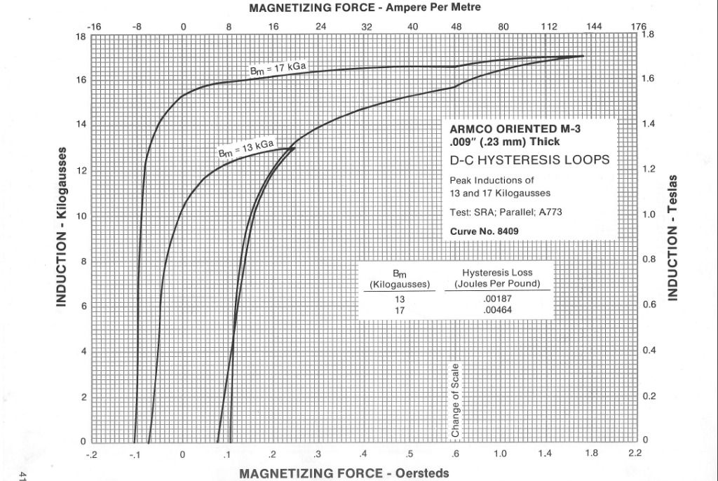
                            Gestalt might possibly have found the material source that will really bring the theme of this thread to life. Check out the BH curve of this material:


                            It has a high saturation, low coercive force, and it is available in ranges from 12 to 2400 Volt-Ampere Cores, the most expensive core being $68. Silicon Steel Toroidal O-Cores - In Stock

                            I ordered two of the 300-600 VA units so we'll see.


                            Dave

                            Comment


                            • #44
                              Originally posted by Web000x View Post
                              Gestalt might possibly have found the material source that will really bring the theme of this thread to life. Check out the BH curve of this material:
                              The problem with any Electrical Steel material is frequency. One of the core material reps informed me that if you are running it at anything much greater than >60Hz, you will begin having issues.
                              A collection of Eric Dollards latest posts and writings on my website: Gestalt Reality - Eric Dollard

                              Comment


                              • #45
                                μ & B-H Plots

                                Introduction

                                I have come across quite a lot of interesting information and now have concluded that the realm of ferro-magnetics is quite the quagmire of non-linear / exponential mathematics! Various phenomena compound one upon the other adding to the overall complexity. Coercive force, hysteresis, Foucault (eddy) currents, initial permeability μ_i due to a threshold H-field that will cause actual magnetization to take place (cause bulk magnetization), ect. To summarize, nothing about ferro-magnetic materials is linear!

                                General Analysis

                                Putting that aside, I've been doing some analysis of the generalized saturable reactor for maximum webers returned with the least amount of source energy needed to do so. This goal has been done with a focus on finding the optimal magnitude of the intrinsic magnetic field H, of the power winding, to be applied during the saturation period engendered by the control winding, which is a very important parameter of efficient operation.

                                Considering that the (potentially) excess energy converging into the circuit is seen as an excess of magnetic field flux. I have focused my efforts into the primary factors involved with the formation of the induced flux B. Which is due impart to many factors, one of which I would like to point out. Notably, from what I can tell, the non-linear permeability μ of the ferro-magnetic material appears to be the key parameter to build around. The little used μ plot, when superimposed upon the B-H plot, helps us find the optimal ampere-turns for the primary winding and overall operating flux density of the power winding. Which give the greatest effective permeability μ seen during the desaturation period for the largest effective inductance swing or change in circuit reactance.

                                Before I jump into that, lets first examine a few B-H plots with the μ shown and derive some conclusions from them.

                                μ & B-H Plots


                                Note the linearity of "free-space" and the paramagnetic & diamagnetic materials


                                Note the NON-LINEARITY of the ferro-magnetic material


                                The plot on the left has LOW squareness ratio, the one on the right has a higher squareness ratio. Note the effects on the rate of change for permeability and its maxima and minima.

                                By definition, μ = B/H. As seen from the above plots, the permeability isn't constant or even linear! This of course for the ferro-magnetic materials. Furthermore, ferro-magnetic matter requires a "threshold" H-field to initiate bulk magnetization. This being the primary cause for the non-linearity seen during the rise of permeability to its maximum value. However this isn't the only reason for the non-linearity seen. As we crank up the H-field, or with a set magnetic path length and set number of turns, the change in current being the only variable in the H-field intensity, we see that the permeability decreases with increasing current. The flux density B now starts to plateau or its rate of growth crawls to a halt, respective to its former rate, and now approximates the rate of growth seen in vacuum by μ_0. This is due to the fact that we now have less and less magnetic domains to flip and align, producing an induced magnetic field flux, for a progressively larger applied H-field. As for the "knee" of the curve, a new phenomena manifests its self here in the form of varying degrees of force needed to flip certain magnetic domain clusters. Some flip easily others require immense amounts of H-field to cause them to align. This is why we don't see a perfect square loop B-H plot, not all the domains flip at the same applied force.

                                For the μ plot (B/H), the section of interest, to my eyes, is the maximum value for μ. This region has the greatest inductance, by virtue of the greatest bulk magnetization seen in the ferro-magnetic matter. If the goal of parametric variation lies in getting the largest delta change in inductance ΔL, then it would seem this region is the sweet spot of operation for any magnetic material or core shape used. From the peak μ, we can now find what amount of ampere-turns to use with the arbitrary magnetic path length of the actual core. With a set number of turns used, the peak μ found and an arbitrary core as the base, we can now find the optimal maximum current flow into the coil during the saturation period. With a set frequency used, we can find the correct current limiting reactance to place inline with the saturable reactor for proper operation. Calculation for an optimally designed power generation unit utilizing synchronous parametric variation via a MagAmp is now child's play. This, for DC-DC or AC operation.

                                Theoretically, total saturation of the core, by the control winding, creates a condition of an effective free-space value for permeability seen by the power winding. Thus giving the least inductance that is theoretically possible for the power winding. The effective delta change in inductance is directly affected by the MINIMUM value of permeability seen when in operation. Therefore, the minimum value for permeability is a very important parameter for converging energy into the circuit. Something of interest, is that the higher the squareness ratio, the easier it is to saturate the core. Which, as can be concluded, is a very desirable characteristic when selecting a core material for a saturable reactor or MagAmp.

                                Heaviside's Commentary

                                Now, let us re-read the profoundly important words of Heaviside:


                                It seems Heaviside was on to something! Paralleling with the first part in red, when operating the MagAmp, we saturate the core, to the effect of an "un-magnetizable medium" equivalent to free-space, we then at the proper time desaturate the core and CHANGE the permeability to a value immensely greater than that of free-space. THIS is EXACTLY what Heaviside was talking about! However, the context in which he was saying these things has little relation to what are doing, but that does not stop what he said from being perfectly accurate in describing what is going on with the unorthodox operation of a MagAmp. Moving on, to the the part in blue, Heaviside then goes on to state the lucid conclusion of what happens in the reverse, or the removal of energy from the circuit! Which has been corroborated by the excellent work of Jim Murray. Jim discovered a "new type of loss" associated with the operation of his special transforming generator, which utilized the general principle of parametric change and therefore exhibited a loss of energy during certain operating points that could not be accounted for with orthodox understandings.

                                Summary

                                It can be concluded that a core material with a high squareness ratio has the steepest response curve and subsequently, the greatest swing between maxima and minima of the core's permeability (B/H). Which is essential for a large delta parameter change. Taking from Heaviside, during the return quarter-period of an AC wave, the total magnetic energy, in number of flux lines, is increased to a quantity Δμ times as great as it was. Thus more energy is returned as excess webers per henry, amperes, (parallel connected) or excess webers per second, volts (series connected). That said, there are many practical limitations on the maximum energy return. But for the most part this is strictly based upon the flux density of highest point of the core material's permeability curve, which sets the limit for the maximum current input for a set number of turns per mean magnetic path length.


                                -------------------------------------------

                                For the full treatment of what I have given on the Heaviside quote Please read the below self-quote:

                                Originally posted by garrettm4 View Post
                                Below is a page from "Forces, Stresses & Fluxes of Energy in the Electromagnetic Field". Published in 1891 in the Proceedings of the Royal Society. Here, Heaviside was preaching his version of Maxwell's electro-magnetic gospel. Heaviside had many disagreements with Maxwell's explanation, and in doing so came to a conclusion that explains, inadvertently, the general principle behind synchronous parameter variation in certain magnetic circuits.


                                I would like to point out more clearly, that "free-space" is considered un-magnetizable. Furthermore, anything that has a greater or lesser permeability than free-space has to be something that "occupies space", i.e. matter. More simply, the presence of matter alters the permeability of the ether, or space itself, at that local point of its presence. Therefore, we always have two different magnetic (or dielectric) quantities, the intrinsic magnetic field H and the induced magnetic field B, due to the magnetization of matter. Furthermore, the synchronicity of the two cannot be made into perfect alignment. While the Intrinsic Field H moves at the speed of light, the Induced Field B has a delay or Hysteresis associated with its propagation due to the magnetization time delay of material entities, seen as the alignment of magnetic domains. This is made more apparent when operating at high frequencies, and is one of the reasons the inductance of an inductor decreases with increasing frequency. (However, at very high frequencies, distributed capacitance becomes the dominant reason.)

                                While we generally can't change the absolute permeability of any medium or material directly, we can however, easily change the effective amount of the relative permeability of a ferromagnetic material. Thus, to change the permeability of the "medium", you have to do it in a very round-about manner. However, Heaviside's commentary remains a concise account, regardless of how you achieve the desired action.
                                -------------------------------------------

                                More to be added later,

                                Garrett M
                                Last edited by garrettm4; 07-31-2012, 09:37 PM.

                                Comment

                                Working...
                                X